EP0260065A2 - Dispositif de réglage du débit - Google Patents
Dispositif de réglage du débit Download PDFInfo
- Publication number
- EP0260065A2 EP0260065A2 EP87307773A EP87307773A EP0260065A2 EP 0260065 A2 EP0260065 A2 EP 0260065A2 EP 87307773 A EP87307773 A EP 87307773A EP 87307773 A EP87307773 A EP 87307773A EP 0260065 A2 EP0260065 A2 EP 0260065A2
- Authority
- EP
- European Patent Office
- Prior art keywords
- fluid
- receiving
- channel
- pivot axis
- fluid jet
- Prior art date
- Legal status (The legal status is an assumption and is not a legal conclusion. Google has not performed a legal analysis and makes no representation as to the accuracy of the status listed.)
- Granted
Links
Images


Classifications
-
- F—MECHANICAL ENGINEERING; LIGHTING; HEATING; WEAPONS; BLASTING
- F15—FLUID-PRESSURE ACTUATORS; HYDRAULICS OR PNEUMATICS IN GENERAL
- F15C—FLUID-CIRCUIT ELEMENTS PREDOMINANTLY USED FOR COMPUTING OR CONTROL PURPOSES
- F15C3/00—Circuit elements having moving parts
- F15C3/10—Circuit elements having moving parts using nozzles or jet pipes
- F15C3/12—Circuit elements having moving parts using nozzles or jet pipes the nozzle or jet pipe being movable
-
- F—MECHANICAL ENGINEERING; LIGHTING; HEATING; WEAPONS; BLASTING
- F15—FLUID-PRESSURE ACTUATORS; HYDRAULICS OR PNEUMATICS IN GENERAL
- F15B—SYSTEMS ACTING BY MEANS OF FLUIDS IN GENERAL; FLUID-PRESSURE ACTUATORS, e.g. SERVOMOTORS; DETAILS OF FLUID-PRESSURE SYSTEMS, NOT OTHERWISE PROVIDED FOR
- F15B13/00—Details of servomotor systems ; Valves for servomotor systems
- F15B13/02—Fluid distribution or supply devices characterised by their adaptation to the control of servomotors
- F15B13/04—Fluid distribution or supply devices characterised by their adaptation to the control of servomotors for use with a single servomotor
- F15B13/042—Fluid distribution or supply devices characterised by their adaptation to the control of servomotors for use with a single servomotor operated by fluid pressure
- F15B13/043—Fluid distribution or supply devices characterised by their adaptation to the control of servomotors for use with a single servomotor operated by fluid pressure with electrically-controlled pilot valves
- F15B13/0436—Fluid distribution or supply devices characterised by their adaptation to the control of servomotors for use with a single servomotor operated by fluid pressure with electrically-controlled pilot valves the pilot valves being of the steerable jet type
Definitions
- This invention relates to fluid control devices and in particular, fluid control devices which utilise the fluid jet principle.
- the present invention is concerned with providing a fluid control device which is compact in construction and which can be manufactured in a relatively straightforward and simple manner.
- a fluid control device comprising a pivotable member having a planar major face and mounted so as to be pivotable about an axis parallel to the major face, the pivotable member including a fluid jet channel which directs a fluid jet parallel to the major face and transverse to the pivot axis at a position remote from the pivot axis, a receiving member defining a fluid receiving channel which is positioned so as to receive the fluid jet, and means operable to pivot the pivotable member about the pivot axis so as to alter the position of the fluid jet channel relative to the fluid receiving channel and thereby vary the quantity of fluid received by the fluid receiving channel.
- a fluid control device comprising a pivotable member having a planar major face and mounted so as to be pivotable about an axis parallel to the major face, the pivotable member including a fluid jet channel which directs a fluid jet parallel to the major face and transverse to the pivot axis at a position remote from the pivot axis, a receiving member defining a fluid receiving channel which is positioned so as to receive the fluid jet, and electromagnet means disposed with poles adjacent and parallel to the major face of the pivotable member and operable to pivot the pivotable member about the pivot axis so as to alter the position of the fluid jet channel relative to the fluid receiving channel and thereby vary the quantity of fluid received by the fluid receiving channel.
- the pivotable member In order for the pivotable member to be pivoted about the pivot axis by the electromagnet means, the pivotable member is made from, or provided with a layer/inserts, of magnetizable material.
- the electromagnet means interacts with the magnetizable material to bring about the pivotal movement.
- the fluid jet channel comprises a nozzle which is incorporated in the pivotable member.
- the fluid jet channel is a deflector means, which redirects a fluid jet towards the fluid receiving channel.
- the fluid control device may include two or more nozzles mounted in the device so as to direct a fluid jet towards the fluid jet channel. The fluid jet channels will then act so as to redirect the fluid jets towards the fluid receiving channels.
- the pivotable member incorporates two fluid jet nozzles, at positions remote from the pivot aixs, and on opposite sides of the pivot axis, which nozzles direct two fluid jets parallel to the major face and transverse to the pivot axis in opposite directions and the receiving member defines two fluid receiving channels, each of which is opposite a fluid jet nozzle to receive fluid therefrom.
- the pivotable member incorporates a fluid supply passage comprising a first duct extending along the pivot axis and a further duct extending from the first duct to the or each fluid jet nozzle.
- a fluid supply passage comprising a first duct extending along the pivot axis and a further duct extending from the first duct to the or each fluid jet nozzle.
- the pivotable member includes two fluid jet deflector channels, each of which is at a position remote from the pivot axis but on opposite sides of the pivot axis, and which direct a fluid jet parallel to the major face and transverse to the pivot axis, and, the receiving member defines two fluid receiving channels, each of which is opposite a fluid jet channel to receive fluid therefrom.
- the fluid jet channels and fluid receiving channels are U-shaped in cross-section.
- the actual shape of the U is a manufacturing/performance related criteria.
- the U-shaped cross-section are in opposition to one another.
- the two fluid jet channels are preferably positioned equidistant from the pivot axis along a common line perpendicular to the pivot axis.
- the pivotable member may comprise a first laminar portion parallel to the major face and made of substantially non-magnetizable material incorporating the or each fluid jet channel, and a second laminar portion made of magnetizable material overlying the first laminar portion and defining the major face.
- the receiving member may surround the pivotable member and serve to pivotally support the pivotable member.
- the receiving member and the pivotable member are integrally formed from a single sheet-like element which is sufficiently flexible to allow pivoting of the pivotable member relative to the receiving member.
- the material of the pivotable member is chosen so that it has a torsional resistance such that it will allow tortional displacements.
- the invention also provides a fluid control device comprising a sheet-like element incorporating cut outs so as to form a receiving member surrounding an integral pivotable member which is so connected to the receiving member as to be pivotable relative to the receiving member about an axis parallel to the major faces of the element, the pivotable member incorporating a fluid jet channel for producing a fluid jet parallel to the major faces and transverse to the pivot axis at a position remote from the pivot axis, the receiving member incorporating a fluid receiving channel which opens opposite the fluid jet channel to receive fluid therefrom, and actuating means operable to pivot the pivotable member about the pivot axis to change the position of the fluid jet channel relative to the fluid receiving channel and to thereby vary the quantity of fluid received by the fluid receiving channel.
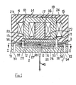
- a fluid control device comprises a base plate 2, a sheet-like element 3 and an upper element 4.
- the sheet-like element 3 incorporates cut outs 5 and 6 forming a receiving member 7 surrounding an integral pivotable member 8 connected to the receiving member 7 by connecting portions 9 and 10 of sufficient flexibility to enable the pivotable member 8 to be pivoted through a limited angle about a pivot axis 11 with respect to the receiving member 7 whilst at the same time providing a certain torsional resistance to such pivotal movement.
- the pivotable member 8 comprises not only a laminar portion 12 integrally formed with the receiving member 7 and made of substantially non-magnetizable material, but also a second laminar portion 13 made of magentizable material which overlies the first laminar portion 12 and is secured thereto mechanically or by adhesive.
- This second laminar portion 13 constitutes an armature.
- the upper element 4 incorporates an electromagnet 14 surrounded by suitable encapsulating material 15.
- the electromagnet 14 incorporates a central permanent magnet 16 and an inverted U-shaped soft iron core 17 having limbs 18 and 19 defining respective opposite poles 20 and 21 disposed adjacent and parallel to a major face 22 of the pivotable member 8 on opposite sides of the pivot axis 11. Eeach of the limbs 18 and 19 is surrounded by a respective actuating coil 23 or 24.
- actuating coils 23 and 24 are suitably electrically energised, a variable magnetic field is superimposed upon the magnetic field associated with the permanent magnet 16 and magnetic interaction takes place between the poles 20 and 21 and the magnetizable material of the armature 13 so as to cause the pivotable member 8 to pivot about the pivot axis 11.
- the portion 12 of the pivotable member 8 has a fluid supply passageway 25 extending therethrough parallel to the major face 22.
- the passageway 25 comprises a first duct 26 extending along the pivot axis 11 and through the connecting portions 9 and 10, and respective further ducts 27 and 28 extending perpendicularly of the first duct 26 in opposite directions and forming fluid jet nozzles 29 and 30 where they open outwardly at opposite ends of the pivotable member 8.
- passageways 31 and 32 comprising ducts 33 and 34 extending through the base plate 2 and ducts 35 and 36 in the receiving member 7 open opposite the fluid jet nozzles 29 and 30 and provide fluid receiving orifices 37 and 38 for receiving fluid from the nozzles 29 and 30.
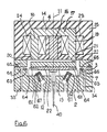
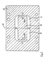
- the laminar portion 12 is formed with two U-shaped fluid jet channels 61 which act to direct fluid jets from nozzles 62 towards respective U-shaped fluid receiving channels 63.
- the relationship of the fluid jet channels 61 to the fluid receiving channels 63 is such that they are inverted with respect to each other.
- the nozzles 62 are mounted in the baseplate 2 of the fluid control device, so that the fluid jets therefrom impinge the fluid jet channel 61 in such a way that they are re-directed (deflected) in a direction parallel to the major face 22 towards the nearest respective secondary major face 64, and the respective fluid receiving channel 63.
- the fluid jet impinges the fluid jet channel, with respect to the direction of flow of the jet, at an acute angle, so that deflection of the jet occurs. It is envisaged that in certain fluid control devices the fluid jet may be deflected through any angle.
- the nozzles 62 are supplied with fluid via the fluid passages 67 in the base plate 2.
- the fluid entering the fluid receiving channel 63 passes along a passage 65 to a chamber 66 and from there onto a respective duct 33, 34.
- Either of the above described forms of fluid control device may be used to form the first stage of a two stage electro-hydraulic servo valve.
- FIG 8 a two stage electro-hydraulic servo valve is illustrated in which the first stage comprises the fluid control device described with reference to Figures 1 to 5 of the drawings. It should however be stressed that the fluid control device described with reference to Figures 6 and 7 could easily perform the same function.
- the second stage comprises a spool valve element 41 located in an elongate chamber 42 having a respective end 43 or 44 in communication with each of the ducts 33 and 34 by way of ducts 45 and 46, so that the position of the spool valve element within the chamber is controlled by the relative fluid pressures within the ducts 33 and 34.
- a feedback wire 40 is secured to the underside of the pivotable member 8 and engages within an annular recess 47 in the spool valve element 41.
- the spool valve element 41 incorporates two annular recesses 48 and 49 in communication with two service ports 50 and 51 for connection, for example, to opposite sides of a hydraulically actuated piston (not shown).
- An inlet port 52 is provided for connection to a source (not shown) of hydraulic fluid under pressure, and two return ports 53 and 54 are provided for connection to a reservoir (not shown).
- Hydraulic fluid supplied to the inlet port 52 passes into a duct 55 having branches 56 and 57 connectable to the recesses 48 and 49 in the spool valve element 41.
- a small proportion of the hydraulic fluid supplied passes by way of a duct 58 incorporating a restriction 59 to the duct 26 extending along the pivot axis of the pivotable member 8.
- the spool valve element 41 may be actuated by an electrical control signal with a particularly rapid response time. Also the gaps between the fluid jet nozzles 29 and 30 in the pivotable member 8 and the fluid receiving orifice 37 and 38 in this construction are substantial by comparison with the diameter of the nozzles 29 and 30.
- the chamber surrounding the pivotable member 8 is maintained at a low pressure relative to the pressure of the jets by virtue of the fact that the chamber is in fluid communication with the return ports 53 and 54 by way of a duct 60 accommodating the feedback wire 40.
- the feedback wire is replaced by two springs provided at opposite ends of the spool valve element and acting to centre the spool valve element.
- pivot axis is disposed equidistant from the two ends of the pivotable member, it should be appreciated that the pivot axis may in other embodiments be provided at different points along the pivotable member.
- the device may include only a single fluid jet nozzle, and the pivot axis may be provided at one end of the pivotable member which will in that case be of cantilever type.
- One or more receiving orifices may be provided in this single fluid jet nozzle arrangement. Multiple fluid jet nozzle arrangements are also feasible.
- nozzles and orifices may be such that a shaped relationship between current input to the device to flow output can be generated.
- the fluid jet nozzles may be formed by nozzle insets introduced into the ends of the ducts in the pivotable member.
- the receiving orifices may be similarly formed by insets introduced into the ends of the ducts in the receiving member.
- the ducts in the pivotable member may be formed in the portion made of substantially non-magnetizable material or may even be formed by separate pipes attached to the lower surface of the pivotable member.
- the ducts may be formed by a laminated construction, for example, by an upper laminate having suitable grooves in its lower surface and a lower laminate having a flat upper surface which is bonded to the lower surface of the upper laminate, or by a three-layer arrangement having an upper laminate with a flat lower surface, a lower laminate with a flat upper surface and an intermediate laminated formed by profiled segments defining the ducts therebetween.
- the pivotable member may be a separate part from the surrounding receiving member.
Landscapes
- Engineering & Computer Science (AREA)
- General Engineering & Computer Science (AREA)
- Physics & Mathematics (AREA)
- Fluid Mechanics (AREA)
- Mechanical Engineering (AREA)
- Theoretical Computer Science (AREA)
- Magnetically Actuated Valves (AREA)
- Servomotors (AREA)
Applications Claiming Priority (2)
| Application Number | Priority Date | Filing Date | Title |
|---|---|---|---|
| GB868621532A GB8621532D0 (en) | 1986-09-06 | 1986-09-06 | Fluid control devices |
| GB8621532 | 1986-09-06 |
Publications (3)
| Publication Number | Publication Date |
|---|---|
| EP0260065A2 true EP0260065A2 (fr) | 1988-03-16 |
| EP0260065A3 EP0260065A3 (en) | 1989-02-22 |
| EP0260065B1 EP0260065B1 (fr) | 1991-11-13 |
Family
ID=10603809
Family Applications (1)
| Application Number | Title | Priority Date | Filing Date |
|---|---|---|---|
| EP19870307773 Expired EP0260065B1 (fr) | 1986-09-06 | 1987-09-03 | Dispositif de réglage du débit |
Country Status (4)
| Country | Link |
|---|---|
| EP (1) | EP0260065B1 (fr) |
| JP (1) | JPS6383406A (fr) |
| DE (1) | DE3774515D1 (fr) |
| GB (1) | GB8621532D0 (fr) |
Cited By (3)
| Publication number | Priority date | Publication date | Assignee | Title |
|---|---|---|---|---|
| EP0629782A3 (fr) * | 1993-03-25 | 1995-04-19 | Festo Kg | Dispositif de commande pour une soupape à voies multiples. |
| US8757588B2 (en) | 2006-04-27 | 2014-06-24 | Buerkert Werke Gmbh | Valve with an electromagnetic drive |
| EP2980417A1 (fr) * | 2014-07-31 | 2016-02-03 | Zodiac Hydraulics | Servovalve à ensemble mobile double |
Families Citing this family (1)
| Publication number | Priority date | Publication date | Assignee | Title |
|---|---|---|---|---|
| US5031653A (en) * | 1990-07-12 | 1991-07-16 | Hr Textron Inc. | Differential cylinder pressure gain compensation for single stage servovalve |
Family Cites Families (8)
| Publication number | Priority date | Publication date | Assignee | Title |
|---|---|---|---|---|
| US2849013A (en) * | 1956-07-27 | 1958-08-26 | Askania Regulator Co | Multiple jet pipe relay regulator |
| US3137309A (en) * | 1962-04-30 | 1964-06-16 | Link Division General Prec Inc | Frictionless zero spring rate seal |
| US3272077A (en) * | 1963-12-23 | 1966-09-13 | Pneumo Dynamics Corp | Hydraulic servo valve |
| GB1206430A (en) * | 1966-10-31 | 1970-09-23 | Weston Hydraulics Ltd | Electro-hydraulic servo valve |
| US3457955A (en) * | 1967-01-03 | 1969-07-29 | Garrett Corp | Aerodynamically balanced valve |
| US3612103A (en) * | 1969-07-01 | 1971-10-12 | Moog Inc | Deflectable free jetstream-type two-stage servo valve |
| US3678951A (en) * | 1970-06-15 | 1972-07-25 | Abex Corp | Method and apparatus for improved jet pipe valve |
| US3765437A (en) * | 1971-03-31 | 1973-10-16 | Renault | Hydraulic free-jet servo-valves |
-
1986
- 1986-09-06 GB GB868621532A patent/GB8621532D0/en active Pending
-
1987
- 1987-09-03 EP EP19870307773 patent/EP0260065B1/fr not_active Expired
- 1987-09-03 DE DE8787307773T patent/DE3774515D1/de not_active Expired - Lifetime
- 1987-09-04 JP JP22179787A patent/JPS6383406A/ja active Pending
Cited By (9)
| Publication number | Priority date | Publication date | Assignee | Title |
|---|---|---|---|---|
| EP0629782A3 (fr) * | 1993-03-25 | 1995-04-19 | Festo Kg | Dispositif de commande pour une soupape à voies multiples. |
| US5443093A (en) * | 1993-03-25 | 1995-08-22 | Festo Kg | Control device for a multiway valve |
| EP0764784A1 (fr) | 1993-03-25 | 1997-03-26 | Festo KG | Dispositif de commande pour une soupape à voies multiples |
| US8757588B2 (en) | 2006-04-27 | 2014-06-24 | Buerkert Werke Gmbh | Valve with an electromagnetic drive |
| US8777181B2 (en) | 2006-04-27 | 2014-07-15 | Buerkert Werke Gmbh | Valve with an electromagnetic drive |
| EP2016319B2 (fr) † | 2006-04-27 | 2020-07-08 | Bürkert Werke GmbH & Co. KG | Soupape avec mécanisme électromagnétique |
| EP2980417A1 (fr) * | 2014-07-31 | 2016-02-03 | Zodiac Hydraulics | Servovalve à ensemble mobile double |
| FR3024505A1 (fr) * | 2014-07-31 | 2016-02-05 | Zodiac Hydraulics | Servovalve a ensemble mobile double |
| US9677682B2 (en) | 2014-07-31 | 2017-06-13 | Zodiac Hydraulics | Servo valve with double mobile assembly |
Also Published As
| Publication number | Publication date |
|---|---|
| EP0260065A3 (en) | 1989-02-22 |
| GB8621532D0 (en) | 1986-10-15 |
| JPS6383406A (ja) | 1988-04-14 |
| EP0260065B1 (fr) | 1991-11-13 |
| DE3774515D1 (de) | 1991-12-19 |
Similar Documents
| Publication | Publication Date | Title |
|---|---|---|
| US4378031A (en) | Electrohydraulic servovalve | |
| EP1080323B1 (fr) | Vanne a commande electrique | |
| US2775254A (en) | Electromagnetic devices for controlling fluid pressure | |
| CN1763384B (zh) | 具有差动辅助返回的直接操作式气动阀 | |
| US4729398A (en) | Current-to-pressure transducers | |
| EP0260065A2 (fr) | Dispositif de réglage du débit | |
| US4796655A (en) | Fluid control devices | |
| US4922963A (en) | Hydraulic servovalve | |
| US4585029A (en) | Electro-hydraulic servo valve | |
| EP1828622B1 (fr) | Procedes et appareils de separation et d'acheminement d'un jet de fluide sous pression dans une servovanne | |
| US20020066480A1 (en) | Pilot stage or pressure control pilot valve having a single armature/flapper | |
| US5303727A (en) | Fluidic deflector jet servovalve | |
| US3339572A (en) | Electro-hydraulic servo valve | |
| US3774644A (en) | Converter for converting electrical signals into fluid signals | |
| US4664135A (en) | Pilot valve | |
| US5129421A (en) | Two-position and three-way valve | |
| JPH0222275B2 (fr) | ||
| GB2163834A (en) | Fluid valve means and method of manufacture | |
| CA1105917A (fr) | Soupape, notamment soupape electromagnetique | |
| JPH0435649Y2 (fr) | ||
| GB2124799A (en) | Electro-hydraulic servo valve | |
| JPS5877905A (ja) | 液圧制御弁 | |
| EP3597937B1 (fr) | Servovanne | |
| JPH0481665B2 (fr) | ||
| JPS58180877A (ja) | 方向制御弁装置 |
Legal Events
| Date | Code | Title | Description |
|---|---|---|---|
| PUAI | Public reference made under article 153(3) epc to a published international application that has entered the european phase |
Free format text: ORIGINAL CODE: 0009012 |
|
| AK | Designated contracting states |
Kind code of ref document: A2 Designated state(s): DE FR GB IT SE |
|
| PUAL | Search report despatched |
Free format text: ORIGINAL CODE: 0009013 |
|
| AK | Designated contracting states |
Kind code of ref document: A3 Designated state(s): DE FR GB IT SE |
|
| RHK1 | Main classification (correction) |
Ipc: F16K 31/10 |
|
| 17P | Request for examination filed |
Effective date: 19890816 |
|
| 17Q | First examination report despatched |
Effective date: 19900327 |
|
| RAP1 | Party data changed (applicant data changed or rights of an application transferred) |
Owner name: ULTRA HYDRAULICS LIMITED |
|
| GRAA | (expected) grant |
Free format text: ORIGINAL CODE: 0009210 |
|
| AK | Designated contracting states |
Kind code of ref document: B1 Designated state(s): DE FR GB IT SE |
|
| PG25 | Lapsed in a contracting state [announced via postgrant information from national office to epo] |
Ref country code: IT Free format text: LAPSE BECAUSE OF FAILURE TO SUBMIT A TRANSLATION OF THE DESCRIPTION OR TO PAY THE FEE WITHIN THE PRE;WARNING: LAPSES OF ITALIAN PATENTS WITH EFFECTIVE DATE BEFORE 2007 MAY HAVE OCCURRED AT ANY TIME BEFORE 2007. THE CORRECT EFFECTIVE DATE MAY BE DIFFERENT FROM THE ONE RECORDED.SCRIBED TIME-LIMIT Effective date: 19911113 Ref country code: FR Effective date: 19911113 Ref country code: SE Effective date: 19911113 |
|
| REF | Corresponds to: |
Ref document number: 3774515 Country of ref document: DE Date of ref document: 19911219 |
|
| EN | Fr: translation not filed | ||
| PGFP | Annual fee paid to national office [announced via postgrant information from national office to epo] |
Ref country code: GB Payment date: 19920824 Year of fee payment: 6 |
|
| PLBE | No opposition filed within time limit |
Free format text: ORIGINAL CODE: 0009261 |
|
| STAA | Information on the status of an ep patent application or granted ep patent |
Free format text: STATUS: NO OPPOSITION FILED WITHIN TIME LIMIT |
|
| PGFP | Annual fee paid to national office [announced via postgrant information from national office to epo] |
Ref country code: DE Payment date: 19920923 Year of fee payment: 6 |
|
| 26N | No opposition filed | ||
| PG25 | Lapsed in a contracting state [announced via postgrant information from national office to epo] |
Ref country code: GB Effective date: 19930903 |
|
| GBPC | Gb: european patent ceased through non-payment of renewal fee |
Effective date: 19930903 |
|
| PG25 | Lapsed in a contracting state [announced via postgrant information from national office to epo] |
Ref country code: DE Effective date: 19940601 |