EP0260119A2 - Gerät zum Lösen der Schraubverbindung eines Pumpenflügelrades - Google Patents
Gerät zum Lösen der Schraubverbindung eines Pumpenflügelrades Download PDFInfo
- Publication number
- EP0260119A2 EP0260119A2 EP87307959A EP87307959A EP0260119A2 EP 0260119 A2 EP0260119 A2 EP 0260119A2 EP 87307959 A EP87307959 A EP 87307959A EP 87307959 A EP87307959 A EP 87307959A EP 0260119 A2 EP0260119 A2 EP 0260119A2
- Authority
- EP
- European Patent Office
- Prior art keywords
- housing
- impeller
- hydraulic cylinder
- pump
- assembly
- Prior art date
- Legal status (The legal status is an assumption and is not a legal conclusion. Google has not performed a legal analysis and makes no representation as to the accuracy of the status listed.)
- Granted
Links
Images

Classifications
-
- B—PERFORMING OPERATIONS; TRANSPORTING
- B25—HAND TOOLS; PORTABLE POWER-DRIVEN TOOLS; MANIPULATORS
- B25B—TOOLS OR BENCH DEVICES NOT OTHERWISE PROVIDED FOR, FOR FASTENING, CONNECTING, DISENGAGING, OR HOLDING
- B25B21/00—Portable power-driven screw or nut setting or loosening tools; Attachments for drilling apparatus serving the same purpose
-
- B—PERFORMING OPERATIONS; TRANSPORTING
- B23—MACHINE TOOLS; METAL-WORKING NOT OTHERWISE PROVIDED FOR
- B23P—METAL-WORKING NOT OTHERWISE PROVIDED FOR; COMBINED OPERATIONS; UNIVERSAL MACHINE TOOLS
- B23P19/00—Machines for simply fitting together or separating metal parts or objects, or metal and non-metal parts, whether or not involving some deformation; Tools or devices therefor so far as not provided for in other classes
- B23P19/04—Machines for simply fitting together or separating metal parts or objects, or metal and non-metal parts, whether or not involving some deformation; Tools or devices therefor so far as not provided for in other classes for assembling or disassembling parts
- B23P19/06—Screw or nut setting or loosening machines
-
- B—PERFORMING OPERATIONS; TRANSPORTING
- B25—HAND TOOLS; PORTABLE POWER-DRIVEN TOOLS; MANIPULATORS
- B25B—TOOLS OR BENCH DEVICES NOT OTHERWISE PROVIDED FOR, FOR FASTENING, CONNECTING, DISENGAGING, OR HOLDING
- B25B13/00—Spanners; Wrenches
- B25B13/48—Spanners; Wrenches for special purposes
- B25B13/50—Spanners; Wrenches for special purposes for operating on work of special profile, e.g. pipes
- B25B13/52—Chain or strap wrenches
-
- B—PERFORMING OPERATIONS; TRANSPORTING
- B25—HAND TOOLS; PORTABLE POWER-DRIVEN TOOLS; MANIPULATORS
- B25B—TOOLS OR BENCH DEVICES NOT OTHERWISE PROVIDED FOR, FOR FASTENING, CONNECTING, DISENGAGING, OR HOLDING
- B25B21/00—Portable power-driven screw or nut setting or loosening tools; Attachments for drilling apparatus serving the same purpose
- B25B21/002—Portable power-driven screw or nut setting or loosening tools; Attachments for drilling apparatus serving the same purpose for special purposes
-
- B—PERFORMING OPERATIONS; TRANSPORTING
- B25—HAND TOOLS; PORTABLE POWER-DRIVEN TOOLS; MANIPULATORS
- B25H—WORKSHOP EQUIPMENT, e.g. FOR MARKING-OUT WORK; STORAGE MEANS FOR WORKSHOPS
- B25H1/00—Work benches; Portable stands or supports for positioning portable tools or work to be operated on thereby
- B25H1/0007—Work benches; Portable stands or supports for positioning portable tools or work to be operated on thereby for engines, motor-vehicles or bicycles
-
- Y—GENERAL TAGGING OF NEW TECHNOLOGICAL DEVELOPMENTS; GENERAL TAGGING OF CROSS-SECTIONAL TECHNOLOGIES SPANNING OVER SEVERAL SECTIONS OF THE IPC; TECHNICAL SUBJECTS COVERED BY FORMER USPC CROSS-REFERENCE ART COLLECTIONS [XRACs] AND DIGESTS
- Y10—TECHNICAL SUBJECTS COVERED BY FORMER USPC
- Y10T—TECHNICAL SUBJECTS COVERED BY FORMER US CLASSIFICATION
- Y10T29/00—Metal working
- Y10T29/53—Means to assemble or disassemble
- Y10T29/53687—Means to assemble or disassemble by rotation of work part
Definitions
- the invention relates to the general field of power apparatus for uncoupling threaded joints in articles of heavy equipment. More particularly, the invention relates to a hydraulically-powered apparatus for uncoupling the threaded connection of large pump impellers.
- This device utilizes a stationary chuck and a rotable chuck, with the structure of the chucks being quite involved.
- the particular structure for the rotatable chuck is specifically designed for tubular bodies.
- United States Patent No. 4,295,257 issued October 20, 1981 to Strohs discloses a work stand for supporting and aligning the various components of a vertical turbine pump during assembly or disassembly.
- the apparatus provides for the power operation of a chain wrench at any location along the work stand, using a hydraulic cylinder to power the chain wrench while a clamp assembly, using a clamping chain and a chain tightener secures the other part of the pump against rotation.
- None of these power apparatus is particularly suited for unthreading the impellers of pumps. In particular, none of these apparatus is adapted to break the threaded connection of impellers of various sizes and right or left-threaded connection.
- the present invention provides a power apparatus for breaking the threaded connections of various-sized and configured pump impellers.
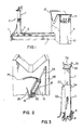
- the invention comprises a V-shaped cradle for receiving the housing of the impeller, an upright vise assembly which is vertically adjustable to secure the end of the impeller shaft furthest from the impeller, and a hydraulic cylinder located on the opposite side of the cradle from the vise assembly having its lower end pivotally fixed along the axis of the apparatus and having a chain and hook connected to its upper end for hooking over a blade of the impeller.
- Activation of the hydraulic cylinder causes torque to be applied to the impeller blade and the threaded connection to be broken.
- the apparatus includes a trolley beam 1, constructed for example of one hundred millimetre steel channel.
- a vise and trolley assembly 2 mounted in the trolley beam is a vise and trolley assembly 2, consisting of a trolley assembly 3, carriage assembly 5, and vise assembly 7.
- the vise and trolley assembly is able to be rolled to any position on the trolley beam by virtue of carriage wheels 6 shown in Fig. 4.
- Trolley stop 11 prevents the carriage from rolling out of the trolley beam and also functions as legs for the trolley beam.
- Housing 10 encloses an electric motor for powering a hydraulic pump, and a reservoir of hydraulic fluid.
- the pump activates the hydraulic cylinders to be described hereafter, using controls 14, all in a known fashion.
- hydraulic cylinder 16 is the main cylinder and is used for breaking the threaded coupling. It is pivotally attached to the housing 10 at 18 by means of a pin through the clevis of the cylinder running through an ear attached to the housing and secured by a cotter pin. Stops 20 and 22 limit the extent to which the cylinder is able to pivot. A slot 24 in the housing allows the hydraulic connection to the cylinder 16 to enter the housing at any angle of the cylinder.
- the cylinder has the usual rod 26 attached to the end of the piston in the cylinder. To the end of the rod is attached a chain 28.
- the vise and trolley assembly consists of the trolley assembly 3 mounted on carriage 5 having four carriage wheels 6.
- the vise assembly 7 is vertically slideable within the trolley assembly 3 so that the height of the vise may be adjusted.
- the height may be power-adjusted using a hydraulic cylinder pivotally secured to the base of the trolley assembly with its piston rod attached to the vise assembly.
- the height of the vise assembly may then be automatically be controlled by controls 14.
- the trolley assembly has an eye 30 to which is secured chain 32. On the opposite side of the trolley assembly is fixed a hook 34 for receiving the chain.
- the vise assembly consists of a V-shaped vise plate 35 shaped to receive the shaft of the impeller, a V-shaped plate 36 having teeth for gripping the shaft of the pump, and a V-shaped plate 38.
- An angle 33 of approximately 10° is formed between the upper edge of the shaft 31 which supports the vise assembly and the horizontal.
- the entire vise assembly, consisting of the vise plate 35, teeth 36 and pivot plate 38 is mounted on a horizontal pivot pin at right angles to the lengthwise direction of the trolley beam which allows the vise assembly to pivot back an angle 10° from the horizontal. This allows the vise assembly to obtain a strong grip on the coupling or shaft despite the fact that the pump rotating assembly may not be perfectly level. Also, it has been found to be preferable to have the pump rotating assembly lower at the end remote from the impeller when breaking the thread in order to diminish the impeller angle on the pulling hook.
- a resilient wooden or rubber slotted insert 37 may be used to place over the impeller blade.
- the pump assembly 40 is placed with the impeller blade 42 projecting over the end of cradle 12 as shown in Fig. 6 and the other end of the pumpshaft resting on vice assembly 7.
- the trolley assembly is positioned at the appropriate distance from the work stand or table 9 by rolling it along the trolley beam.
- the hydraulic cylinder in the vise and trolley assembly is activated to raise or lower the vise assembly until the pump shaft is approximately level.
- Hold-down chain 32 is then led over the shaft or coupling and hooked onto hook 34.
- the hydraulic cylinder is then activated to raise the vise assembly and tighten the shaft or coupling against the teeth 36 of the vise assembly.
- Main cylinder 16 is pivoted to one side or the other of its range of travel depending on whether the impeller is a right or left-hand thread.
- the chain is then led over the impeller blade and hook 29 hooked over one of the blades.
- the cylinder is then activated to tighten the chain and uncouple the threaded coupling.
- the invention is particularly adapted for unthreading the threaded connection of an impeller of varying size and shape.
- the movement of the carriage assembly along the trolley beam and the raising or lowering of the vise assembly shaft allows for adjustment to the various pump assembly sizes.
- the pivoting capacity of the main cyclinder 16 allows it to not only adjust to impellers of various diameters, but also to impellers having right or left-handed threads.
Landscapes
- Engineering & Computer Science (AREA)
- Mechanical Engineering (AREA)
- Structures Of Non-Positive Displacement Pumps (AREA)
Priority Applications (1)
| Application Number | Priority Date | Filing Date | Title |
|---|---|---|---|
| AT87307959T ATE85254T1 (de) | 1986-09-12 | 1987-09-09 | Geraet zum loesen der schraubverbindung eines pumpenfluegelrades. |
Applications Claiming Priority (2)
| Application Number | Priority Date | Filing Date | Title |
|---|---|---|---|
| CA518120 | 1986-09-12 | ||
| CA000518120A CA1267005A (en) | 1986-09-12 | 1986-09-12 | Apparatus for uncoupling the threaded connection of a pump impeller |
Publications (3)
| Publication Number | Publication Date |
|---|---|
| EP0260119A2 true EP0260119A2 (de) | 1988-03-16 |
| EP0260119A3 EP0260119A3 (en) | 1989-08-30 |
| EP0260119B1 EP0260119B1 (de) | 1993-02-03 |
Family
ID=4133924
Family Applications (1)
| Application Number | Title | Priority Date | Filing Date |
|---|---|---|---|
| EP87307959A Expired - Lifetime EP0260119B1 (de) | 1986-09-12 | 1987-09-09 | Gerät zum Lösen der Schraubverbindung eines Pumpenflügelrades |
Country Status (5)
| Country | Link |
|---|---|
| US (1) | US4843702A (de) |
| EP (1) | EP0260119B1 (de) |
| AT (1) | ATE85254T1 (de) |
| CA (1) | CA1267005A (de) |
| DE (1) | DE3783980T2 (de) |
Cited By (1)
| Publication number | Priority date | Publication date | Assignee | Title |
|---|---|---|---|---|
| CN104128918A (zh) * | 2014-07-18 | 2014-11-05 | 四川万冠机电技术有限公司 | 一种泵安装工装台 |
Families Citing this family (10)
| Publication number | Priority date | Publication date | Assignee | Title |
|---|---|---|---|---|
| FI87391C (fi) * | 1989-03-23 | 1992-12-28 | Tampella Oy Ab | Anordning foer hantering av borrstaenger i bergborrmaskineri el. dyl. |
| JP2799233B2 (ja) * | 1990-08-27 | 1998-09-17 | 北海製罐株式会社 | 二重巻締機におけるカバーフィードターレットの着脱装置 |
| US5099725A (en) * | 1990-10-19 | 1992-03-31 | Franks Casing Crew And Rental Tools, Inc. | Torque transfer apparatus |
| US6098974A (en) * | 1994-04-28 | 2000-08-08 | Globe Products Inc. | Armature support pallet |
| US6533246B1 (en) * | 1999-12-13 | 2003-03-18 | Jeffrey A. Hulligan | Shoe clamp |
| CN102416610A (zh) * | 2011-09-21 | 2012-04-18 | 江苏盛虹科技股份有限公司 | 卷绕机卡盘拆装工具车 |
| CN104942751A (zh) * | 2015-07-20 | 2015-09-30 | 苏州新达电扶梯部件有限公司 | 一种变径托举工装 |
| US10105834B2 (en) * | 2015-11-09 | 2018-10-23 | Ridge Tool Company | Adapters for chain pipe vises |
| CN105729103A (zh) * | 2016-04-29 | 2016-07-06 | 沈阳透平机械股份有限公司 | 液压拆装式叶轮用螺栓杆拉伸装置及方法 |
| CN114905468A (zh) * | 2022-05-31 | 2022-08-16 | 利华益维远化学股份有限公司 | 用于机泵检维修的移动小车 |
Family Cites Families (7)
| Publication number | Priority date | Publication date | Assignee | Title |
|---|---|---|---|---|
| US2495475A (en) * | 1946-09-27 | 1950-01-24 | Hastings Mfg Co | Air wrench |
| US3256757A (en) * | 1963-01-15 | 1966-06-21 | United States Steel Corp | Power wrench for breaking threaded joints |
| US3900938A (en) * | 1974-10-21 | 1975-08-26 | Tuxco Corp | Hydraulic cylinder service machine |
| US3963231A (en) * | 1974-11-25 | 1976-06-15 | The Pandjiris Weldment Co. | Pipe positioning, rotating and fitting apparatus for welding |
| US4092881A (en) * | 1976-10-29 | 1978-06-06 | Christensen, Inc. | Apparatus for making-up and breaking threaded pipe connections |
| US4295257A (en) * | 1980-02-20 | 1981-10-20 | Strohs Robert F | Work stand for vertical turbine pumps |
| US4723348A (en) * | 1986-09-15 | 1988-02-09 | Deere & Company | Hydraulic cylinder repair fixture |
-
1986
- 1986-09-12 CA CA000518120A patent/CA1267005A/en not_active Expired - Lifetime
-
1987
- 1987-09-09 AT AT87307959T patent/ATE85254T1/de not_active IP Right Cessation
- 1987-09-09 DE DE8787307959T patent/DE3783980T2/de not_active Expired - Fee Related
- 1987-09-09 EP EP87307959A patent/EP0260119B1/de not_active Expired - Lifetime
-
1988
- 1988-01-19 US US07/145,505 patent/US4843702A/en not_active Expired - Lifetime
Cited By (1)
| Publication number | Priority date | Publication date | Assignee | Title |
|---|---|---|---|---|
| CN104128918A (zh) * | 2014-07-18 | 2014-11-05 | 四川万冠机电技术有限公司 | 一种泵安装工装台 |
Also Published As
| Publication number | Publication date |
|---|---|
| EP0260119B1 (de) | 1993-02-03 |
| DE3783980T2 (de) | 1993-08-19 |
| ATE85254T1 (de) | 1993-02-15 |
| CA1267005A (en) | 1990-03-27 |
| EP0260119A3 (en) | 1989-08-30 |
| DE3783980D1 (de) | 1993-03-18 |
| US4843702A (en) | 1989-07-04 |
Similar Documents
| Publication | Publication Date | Title |
|---|---|---|
| US4051587A (en) | Pile handling apparatus and methods | |
| EP0260119A2 (de) | Gerät zum Lösen der Schraubverbindung eines Pumpenflügelrades | |
| US20050022353A1 (en) | Portable plastic pipe cutter beveller system | |
| US7942081B2 (en) | Automatically adjustable power jaw | |
| CA2293982C (en) | Support for mounting a tool on a pipe | |
| US4295257A (en) | Work stand for vertical turbine pumps | |
| US5919009A (en) | Boring system and method | |
| CN108818403A (zh) | 一种缸套拆卸装置 | |
| US4345493A (en) | Drill rod holding and break-out device | |
| CN216399448U (zh) | 一种管道施工用多功能辅助固定结构 | |
| US5074143A (en) | Cart for removing and installing dies in a cut-off press | |
| US5123803A (en) | Stern drive handling device | |
| CN112922542A (zh) | 一种大螺旋插接式钻杆自动加卸装置及方法 | |
| CN216805525U (zh) | 一种便于中央空调安装的可移动装置 | |
| CN109138871B (zh) | 一种钻具鼠洞液压夹紧和升降装置 | |
| JPS63501780A (ja) | パイプ接合装置 | |
| US6990712B2 (en) | Pipe joining tool | |
| US3927457A (en) | Pipe-seating apparatus | |
| JP2628680B2 (ja) | ポンプの羽根車のねじ連結部をはずすための装置 | |
| CN116765726B (zh) | 一种自动化焊接装置及其方法 | |
| CN219093862U (zh) | 阀杆头部快速倒角设备 | |
| CN214161830U (zh) | 一种用于起重机零件的焊接装置 | |
| US2374871A (en) | Apparatus for applying and removing valve fittings in gas cylinders | |
| CN211464723U (zh) | 一种便于水平转动锻件的锻造操作机及其机械手夹具 | |
| GB2230988A (en) | Torquing device |
Legal Events
| Date | Code | Title | Description |
|---|---|---|---|
| PUAI | Public reference made under article 153(3) epc to a published international application that has entered the european phase |
Free format text: ORIGINAL CODE: 0009012 |
|
| AK | Designated contracting states |
Kind code of ref document: A2 Designated state(s): AT BE CH DE ES FR GB GR IT LI LU NL SE |
|
| PUAL | Search report despatched |
Free format text: ORIGINAL CODE: 0009013 |
|
| AK | Designated contracting states |
Kind code of ref document: A3 Designated state(s): AT BE CH DE ES FR GB GR IT LI LU NL SE |
|
| 17P | Request for examination filed |
Effective date: 19900215 |
|
| 17Q | First examination report despatched |
Effective date: 19910312 |
|
| GRAA | (expected) grant |
Free format text: ORIGINAL CODE: 0009210 |
|
| AK | Designated contracting states |
Kind code of ref document: B1 Designated state(s): AT BE CH DE ES FR GB GR IT LI LU NL SE |
|
| PG25 | Lapsed in a contracting state [announced via postgrant information from national office to epo] |
Ref country code: IT Free format text: LAPSE BECAUSE OF FAILURE TO SUBMIT A TRANSLATION OF THE DESCRIPTION OR TO PAY THE FEE WITHIN THE PRE;WARNING: LAPSES OF ITALIAN PATENTS WITH EFFECTIVE DATE BEFORE 2007 MAY HAVE OCCURRED AT ANY TIME BEFORE 2007. THE CORRECT EFFECTIVE DATE MAY BE DIFFERENT FROM THE ONE RECORDED.SCRIBED TIME-LIMIT Effective date: 19930203 Ref country code: LI Effective date: 19930203 Ref country code: NL Effective date: 19930203 Ref country code: GR Free format text: LAPSE BECAUSE OF FAILURE TO SUBMIT A TRANSLATION OF THE DESCRIPTION OR TO PAY THE FEE WITHIN THE PRESCRIBED TIME-LIMIT Effective date: 19930203 Ref country code: CH Effective date: 19930203 Ref country code: BE Effective date: 19930203 Ref country code: AT Effective date: 19930203 |
|
| REF | Corresponds to: |
Ref document number: 85254 Country of ref document: AT Date of ref document: 19930215 Kind code of ref document: T |
|
| REF | Corresponds to: |
Ref document number: 3783980 Country of ref document: DE Date of ref document: 19930318 |
|
| PG25 | Lapsed in a contracting state [announced via postgrant information from national office to epo] |
Ref country code: ES Free format text: LAPSE BECAUSE OF FAILURE TO SUBMIT A TRANSLATION OF THE DESCRIPTION OR TO PAY THE FEE WITHIN THE PRESCRIBED TIME-LIMIT Effective date: 19930514 |
|
| REG | Reference to a national code |
Ref country code: CH Ref legal event code: PL |
|
| ET | Fr: translation filed | ||
| NLV1 | Nl: lapsed or annulled due to failure to fulfill the requirements of art. 29p and 29m of the patents act | ||
| PG25 | Lapsed in a contracting state [announced via postgrant information from national office to epo] |
Ref country code: LU Free format text: LAPSE BECAUSE OF NON-PAYMENT OF DUE FEES Effective date: 19930930 |
|
| PLBE | No opposition filed within time limit |
Free format text: ORIGINAL CODE: 0009261 |
|
| STAA | Information on the status of an ep patent application or granted ep patent |
Free format text: STATUS: NO OPPOSITION FILED WITHIN TIME LIMIT |
|
| 26N | No opposition filed | ||
| EAL | Se: european patent in force in sweden |
Ref document number: 87307959.4 |
|
| PGFP | Annual fee paid to national office [announced via postgrant information from national office to epo] |
Ref country code: GB Payment date: 19970902 Year of fee payment: 11 |
|
| PGFP | Annual fee paid to national office [announced via postgrant information from national office to epo] |
Ref country code: FR Payment date: 19970917 Year of fee payment: 11 |
|
| PGFP | Annual fee paid to national office [announced via postgrant information from national office to epo] |
Ref country code: SE Payment date: 19970923 Year of fee payment: 11 |
|
| PGFP | Annual fee paid to national office [announced via postgrant information from national office to epo] |
Ref country code: DE Payment date: 19970930 Year of fee payment: 11 |
|
| PG25 | Lapsed in a contracting state [announced via postgrant information from national office to epo] |
Ref country code: GB Free format text: LAPSE BECAUSE OF NON-PAYMENT OF DUE FEES Effective date: 19980909 |
|
| PG25 | Lapsed in a contracting state [announced via postgrant information from national office to epo] |
Ref country code: SE Free format text: LAPSE BECAUSE OF NON-PAYMENT OF DUE FEES Effective date: 19980910 |
|
| GBPC | Gb: european patent ceased through non-payment of renewal fee |
Effective date: 19980909 |
|
| EUG | Se: european patent has lapsed |
Ref document number: 87307959.4 |
|
| PG25 | Lapsed in a contracting state [announced via postgrant information from national office to epo] |
Ref country code: FR Free format text: LAPSE BECAUSE OF NON-PAYMENT OF DUE FEES Effective date: 19990531 |
|
| PG25 | Lapsed in a contracting state [announced via postgrant information from national office to epo] |
Ref country code: DE Free format text: LAPSE BECAUSE OF NON-PAYMENT OF DUE FEES Effective date: 19990701 |
|
| REG | Reference to a national code |
Ref country code: FR Ref legal event code: ST |