EP0260177A1 - Vorrichtung zum Aufspüren von unregelmässigen Schwankungen der Verbrennung in den Verbrennungsräumen eines Ottomotors mit gesteuerter Zündung - Google Patents
Vorrichtung zum Aufspüren von unregelmässigen Schwankungen der Verbrennung in den Verbrennungsräumen eines Ottomotors mit gesteuerter Zündung Download PDFInfo
- Publication number
- EP0260177A1 EP0260177A1 EP87401893A EP87401893A EP0260177A1 EP 0260177 A1 EP0260177 A1 EP 0260177A1 EP 87401893 A EP87401893 A EP 87401893A EP 87401893 A EP87401893 A EP 87401893A EP 0260177 A1 EP0260177 A1 EP 0260177A1
- Authority
- EP
- European Patent Office
- Prior art keywords
- coil
- spark plug
- detection circuit
- electrodes
- low
- Prior art date
- Legal status (The legal status is an assumption and is not a legal conclusion. Google has not performed a legal analysis and makes no representation as to the accuracy of the status listed.)
- Granted
Links
- 238000002485 combustion reaction Methods 0.000 title claims abstract description 20
- 230000001788 irregular Effects 0.000 title 1
- 238000001514 detection method Methods 0.000 claims abstract description 27
- 238000005259 measurement Methods 0.000 claims 5
- 239000000203 mixture Substances 0.000 description 3
- 238000010586 diagram Methods 0.000 description 2
- 239000007789 gas Substances 0.000 description 2
- 238000002347 injection Methods 0.000 description 2
- 239000007924 injection Substances 0.000 description 2
- 230000003068 static effect Effects 0.000 description 2
- 230000003416 augmentation Effects 0.000 description 1
- 230000009172 bursting Effects 0.000 description 1
- 238000006243 chemical reaction Methods 0.000 description 1
- 230000003247 decreasing effect Effects 0.000 description 1
- 230000005684 electric field Effects 0.000 description 1
- 230000005686 electrostatic field Effects 0.000 description 1
- 238000001914 filtration Methods 0.000 description 1
- 239000003574 free electron Substances 0.000 description 1
- 230000010354 integration Effects 0.000 description 1
- 230000007257 malfunction Effects 0.000 description 1
- 238000004519 manufacturing process Methods 0.000 description 1
- 238000000034 method Methods 0.000 description 1
- 230000010287 polarization Effects 0.000 description 1
- 238000005215 recombination Methods 0.000 description 1
- 230000006798 recombination Effects 0.000 description 1
- 230000035945 sensitivity Effects 0.000 description 1
- 239000000126 substance Substances 0.000 description 1
- 238000006467 substitution reaction Methods 0.000 description 1
Images

Classifications
-
- F—MECHANICAL ENGINEERING; LIGHTING; HEATING; WEAPONS; BLASTING
- F02—COMBUSTION ENGINES; HOT-GAS OR COMBUSTION-PRODUCT ENGINE PLANTS
- F02P—IGNITION, OTHER THAN COMPRESSION IGNITION, FOR INTERNAL-COMBUSTION ENGINES; TESTING OF IGNITION TIMING IN COMPRESSION-IGNITION ENGINES
- F02P5/00—Advancing or retarding ignition; Control therefor
- F02P5/04—Advancing or retarding ignition; Control therefor automatically, as a function of the working conditions of the engine or vehicle or of the atmospheric conditions
- F02P5/145—Advancing or retarding ignition; Control therefor automatically, as a function of the working conditions of the engine or vehicle or of the atmospheric conditions using electrical means
- F02P5/15—Digital data processing
- F02P5/152—Digital data processing dependent on pinking
-
- F—MECHANICAL ENGINEERING; LIGHTING; HEATING; WEAPONS; BLASTING
- F02—COMBUSTION ENGINES; HOT-GAS OR COMBUSTION-PRODUCT ENGINE PLANTS
- F02P—IGNITION, OTHER THAN COMPRESSION IGNITION, FOR INTERNAL-COMBUSTION ENGINES; TESTING OF IGNITION TIMING IN COMPRESSION-IGNITION ENGINES
- F02P17/00—Testing of ignition installations, e.g. in combination with adjusting; Testing of ignition timing in compression-ignition engines
- F02P17/12—Testing characteristics of the spark, ignition voltage or current
-
- G—PHYSICS
- G01—MEASURING; TESTING
- G01L—MEASURING FORCE, STRESS, TORQUE, WORK, MECHANICAL POWER, MECHANICAL EFFICIENCY, OR FLUID PRESSURE
- G01L23/00—Devices or apparatus for measuring or indicating or recording rapid changes, such as oscillations, in the pressure of steam, gas, or liquid; Indicators for determining work or energy of steam, internal-combustion, or other fluid-pressure engines from the condition of the working fluid
- G01L23/22—Devices or apparatus for measuring or indicating or recording rapid changes, such as oscillations, in the pressure of steam, gas, or liquid; Indicators for determining work or energy of steam, internal-combustion, or other fluid-pressure engines from the condition of the working fluid for detecting or indicating knocks in internal-combustion engines; Units comprising pressure-sensitive members combined with ignitors for firing internal-combustion engines
- G01L23/221—Devices or apparatus for measuring or indicating or recording rapid changes, such as oscillations, in the pressure of steam, gas, or liquid; Indicators for determining work or energy of steam, internal-combustion, or other fluid-pressure engines from the condition of the working fluid for detecting or indicating knocks in internal-combustion engines; Units comprising pressure-sensitive members combined with ignitors for firing internal-combustion engines for detecting or indicating knocks in internal combustion engines
- G01L23/225—Devices or apparatus for measuring or indicating or recording rapid changes, such as oscillations, in the pressure of steam, gas, or liquid; Indicators for determining work or energy of steam, internal-combustion, or other fluid-pressure engines from the condition of the working fluid for detecting or indicating knocks in internal-combustion engines; Units comprising pressure-sensitive members combined with ignitors for firing internal-combustion engines for detecting or indicating knocks in internal combustion engines circuit arrangements therefor
-
- F—MECHANICAL ENGINEERING; LIGHTING; HEATING; WEAPONS; BLASTING
- F02—COMBUSTION ENGINES; HOT-GAS OR COMBUSTION-PRODUCT ENGINE PLANTS
- F02P—IGNITION, OTHER THAN COMPRESSION IGNITION, FOR INTERNAL-COMBUSTION ENGINES; TESTING OF IGNITION TIMING IN COMPRESSION-IGNITION ENGINES
- F02P17/00—Testing of ignition installations, e.g. in combination with adjusting; Testing of ignition timing in compression-ignition engines
- F02P17/12—Testing characteristics of the spark, ignition voltage or current
- F02P2017/125—Measuring ionisation of combustion gas, e.g. by using ignition circuits
- F02P2017/128—Measuring ionisation of combustion gas, e.g. by using ignition circuits for knock detection
-
- Y—GENERAL TAGGING OF NEW TECHNOLOGICAL DEVELOPMENTS; GENERAL TAGGING OF CROSS-SECTIONAL TECHNOLOGIES SPANNING OVER SEVERAL SECTIONS OF THE IPC; TECHNICAL SUBJECTS COVERED BY FORMER USPC CROSS-REFERENCE ART COLLECTIONS [XRACs] AND DIGESTS
- Y02—TECHNOLOGIES OR APPLICATIONS FOR MITIGATION OR ADAPTATION AGAINST CLIMATE CHANGE
- Y02T—CLIMATE CHANGE MITIGATION TECHNOLOGIES RELATED TO TRANSPORTATION
- Y02T10/00—Road transport of goods or passengers
- Y02T10/10—Internal combustion engine [ICE] based vehicles
- Y02T10/40—Engine management systems
Definitions
- the present invention relates to a device for detecting a combustion anomaly in an internal combustion engine cylinder with positive ignition.
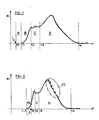
- FIG. 1 of the appended drawings shows the evolution of the ionization signal ei as a function of the time considered between the ignition instant t0 and the instant t4 of end of combustion.
- This ionization signal can be separated into four zones: - A zone A where no ionization signal appears, the part of the gases in combustion moving away from the spark plug at a speed greater than that of the flame front (the ignition being considered as punctual in time); - an area B of rise of the ionization current when the spark plug is reached by the flame front; - a zone C corresponding to a very tormented level due to violent chemical reactions at the level of the spark plug; and - a zone D closely matching the shape of the pressure curve in the chamber.
- the shape of the ionization signal in this area is the combination of the increase in electronic density per aug mentation of the pressure and the recombination of free radicals (+ and -) and electrons.
- FIG. 2 shows that observation of the ionization signal makes it possible to detect combustion anomalies in an internal combustion engine cylinder.
- a pre-ignition located near the spark plug will show an ionization signal before the ignition point, while a pre-ignition away from the spark plug will make the ionization voltage hump in zone 4 closer in time of the ignition signal generated at time t0.
- U.S. Patent No. 4,491,110 describes a device that exploits the correlation between changes in the pressure in the combustion chamber and the ionisation signal.
- This device is of the type comprising a spark plug comprising at least two electrodes, an ignition circuit comprising a coil, the secondary of which is connected in series with the spark plug electrodes, a low-voltage DC source for biasing the electrodes. the spark plug, a circuit for detecting the ionization current generated in the cylinder during the combustion phase, and means for decoupling from the detection circuit the high voltage applied by the secondary of the coil to the spark plug.
- the detection circuit is connected, in parallel with the secondary of the coil, directly to one of the spark plug electrodes, in this case the central electrode.
- This requires the use of a very high pressure diode (THT) connected between this electrode and the detection circuit to prevent the very high voltage generated by the secondary of the coil at the time of ignition is not applied to the detection circuit.
- THT diodes are expensive and have the disadvantage of having a large size and questionable reliability while being difficult to use because of the high manipulated voltages, their sensitivity to humidity and the presence of phenomena. 'effluvage.
- the configuration of the assembly described in the aforementioned American patent requires the use of a THT diode per spark plug, which increases the cost of the device accordingly and multiplies the sources of malfunction.
- the invention aims to eliminate the aforementioned drawbacks by means of a device for detecting a combustion anomaly in a cylinder of an internal combustion engine with positive ignition, the ionization current detection circuit of which is decoupled from very high voltage. generated by the secondary of the coil without using a THT diode.
- the invention relates to a device of the aforementioned type characterized in that said coil has a secondary with low impedance and high bandwidth connected in series between said electrodes and said detection circuit and in that said decoupling means comprise a low-voltage non-return diode connected in parallel with said detection circuit.
- block 1 designates all of the electronic circuits which, as a function of the engine operating parameters, control the conduction of the primary 2a of the coil 2 and the instant of ignition.
- These electronic circuits which may include, for example, analog parameters acquisition circuits, an electronic computer and a power circuit for supplying the primary 2a, are well known to those skilled in the art and will therefore not be described in detail.
- the secondary 2b of the coil is of the low impedance type (for example 680 ⁇ ) and large bandwidth (of the order of 40,000 Hz).
- This secondary 2b is connected in series between the electrodes of a spark plug 3 and a detection circuit comprising the series connection of a resistor 4 and of a continuous low-voltage source 5 connected between the resistor 4 and the ground.
- Resistor 4 has a value of 20 kilos ⁇ while source 5 develops across its terminals a direct voltage of the order of 2 to 300 volts.
- the detection circuit is completed by a processing chain 6 which measures the voltage developed at the terminals of the resistor 4, performs a certain number of processing operations on the signal thus collected to determine, for example whether one is in the presence of d 'a knocking phenomenon and delivers the information corresponding to block 1 which, in the event of knocking detection, corrects the angle of advance on ignition in the direction of its decrease.
- the information from chain 6 can be applied to an injection computer or to a supercharging circuit management computer an engine if the latter is fitted with one or more turbochargers.
- these different injection ignition functions and management of the boost circuit can be performed by the same computer. There is no need here to go into the detail of the description and operation of the processing chain 6 because this kind of circuit is already the subject of mass production well known to those skilled in the art. .
- the device of FIG. 3 is completed by a low-voltage non-return diode 7 connected in parallel with the series connection of the resistor 4 with the low-voltage source 5.
- the anode of the diode 7 is connected as the positive pole of the source 5 to ground, while its cathode is connected to the common point of the resistor 4 and the secondary 2b of the ignition coil 2 (8).
- the source 5 permanently applies a positive polarization at point 8.
- a very high voltage of the order of 20 kv develops across secondary 2b, with reverse polarity.
- the detection circuit 4, 5 and 6 is decoupled from the high voltage by the non-return diode 7. Because the secondary 2b of the coil has a very low impedance, it behaves like a voltage generator and the current flowing therein is fixed by the value of the resistor 4 and by the ionization phenomena which develop in the gas mixture surrounding the spark plug electrodes 3.
- This ionization current passing through the resistor 4 develops at its terminals a voltage ei representative of the pressure in the cylinder.
- This voltage is detected by the chain 6 which performs the necessary processing and delivers the desired information to the circuit 1. If the chain 6 is intended to ensure knock detection, it ensures operations conventional filtering, integration and comparison with one or more threshold (s) in order to determine whether the voltage ei detected is representative or not of a knock phenomenon.
- FIG. 4 shows the detection circuit 4-6 associated with a static distribution ignition system for a multi-cylinder engine.
- This system includes, as known per se, ignition coils 2.1, 2.2, 2.3, 2.4 associated with the spark plugs 3.1, 3.2, 3.3 and 3.4 respectively.
- Sequential control of the primary of each of the coils is provided from block 1 by electronic circuits, for example thyristor, well known to those skilled in the art.
- a single diode 7 and a single detection circuit 4-6 connected to the secondary of the different coils is sufficient to ensure decoupling between the high voltage developed successively at the terminals of the different coils and the detection circuit 4-6.
- the device of the aforementioned US patent would also require as many high-voltage diodes as spark plugs.
Landscapes
- Engineering & Computer Science (AREA)
- Chemical & Material Sciences (AREA)
- Combustion & Propulsion (AREA)
- Mechanical Engineering (AREA)
- General Engineering & Computer Science (AREA)
- Physics & Mathematics (AREA)
- General Physics & Mathematics (AREA)
- Signal Processing (AREA)
- Ignition Installations For Internal Combustion Engines (AREA)
Applications Claiming Priority (2)
| Application Number | Priority Date | Filing Date | Title |
|---|---|---|---|
| FR8612119 | 1986-08-27 | ||
| FR8612119A FR2603339B1 (fr) | 1986-08-27 | 1986-08-27 | Dispositif de detection d'anomalie de combustion dans un cylindre de moteur a combustion interne a allumage commande |
Publications (2)
| Publication Number | Publication Date |
|---|---|
| EP0260177A1 true EP0260177A1 (de) | 1988-03-16 |
| EP0260177B1 EP0260177B1 (de) | 1991-05-29 |
Family
ID=9338530
Family Applications (1)
| Application Number | Title | Priority Date | Filing Date |
|---|---|---|---|
| EP87401893A Expired - Lifetime EP0260177B1 (de) | 1986-08-27 | 1987-08-17 | Vorrichtung zum Aufspüren von unregelmässigen Schwankungen der Verbrennung in den Verbrennungsräumen eines Ottomotors mit gesteuerter Zündung |
Country Status (4)
| Country | Link |
|---|---|
| EP (1) | EP0260177B1 (de) |
| DE (1) | DE3770380D1 (de) |
| ES (1) | ES2022405B3 (de) |
| FR (1) | FR2603339B1 (de) |
Cited By (10)
| Publication number | Priority date | Publication date | Assignee | Title |
|---|---|---|---|---|
| FR2734022A1 (fr) * | 1995-05-10 | 1996-11-15 | Nippon Soken | Appareil de surveillance de la combustion dans un moteur a combustion interne |
| EP0752581A3 (de) * | 1995-07-05 | 1997-02-12 | Telefunken Microelectron | |
| WO1997013259A1 (en) * | 1995-10-05 | 1997-04-10 | Alliedsignal Inc. | Magnetic core-coil assembly for spark ignition systems |
| DE19605803A1 (de) * | 1996-02-16 | 1997-08-21 | Daug Deutsche Automobilgesells | Schaltungsanordnung zur Ionenstrommessung |
| WO1997047875A1 (en) * | 1996-06-12 | 1997-12-18 | Sem Ab | A method for detecting an ion current |
| GB2396187A (en) * | 2002-11-01 | 2004-06-16 | Visteon Global Tech Inc | I.c. engine in-cylinder ionization detection system with ionization detection circuit and ignition coil driver circuit integrated into a single package |
| GB2396754A (en) * | 2002-11-01 | 2004-06-30 | Visteon Global Tech Inc | A regulated power supply for in cylinder ionization detection using a charge pump |
| DE19781522B4 (de) * | 1996-11-18 | 2004-10-28 | Mecel Ab | Vorrichtung und Verfahren zur Ionisationsdetektion in Mehrzylinder-Verbrennungsmotoren |
| GB2409356A (en) * | 2003-12-17 | 2005-06-22 | Visteon Global Tech Inc | A regulated power supply for in-cylinder ionization detection using ignition coil fly back energy and two-stage regulation |
| EP1132601B1 (de) * | 2000-03-10 | 2005-09-21 | Delphi Technologies, Inc. | Verfahren zum Regeln der Verbrennung fossiler Brennstoffe |
Families Citing this family (1)
| Publication number | Priority date | Publication date | Assignee | Title |
|---|---|---|---|---|
| FR2899394B1 (fr) * | 2006-04-03 | 2008-05-16 | Renault Sas | Procede de mesure d'un courant d'ionisation d'une bougie de type a structure resonante, et dispositif correspondant |
Family Cites Families (1)
| Publication number | Priority date | Publication date | Assignee | Title |
|---|---|---|---|---|
| JPS6157830A (ja) * | 1984-08-30 | 1986-03-24 | Nec Home Electronics Ltd | 異常燃焼判定方法および装置 |
-
1986
- 1986-08-27 FR FR8612119A patent/FR2603339B1/fr not_active Expired
-
1987
- 1987-08-17 EP EP87401893A patent/EP0260177B1/de not_active Expired - Lifetime
- 1987-08-17 DE DE8787401893T patent/DE3770380D1/de not_active Expired - Lifetime
- 1987-08-17 ES ES87401893T patent/ES2022405B3/es not_active Expired - Lifetime
Non-Patent Citations (1)
| Title |
|---|
| PATENT ABSTRACTS OF JAPAN, vol. 10, no. 220 (P-482) [2276], 31 juillet 1986; & JP-A-61 57 830 (NEC HOME ELECTRONICS LTD) 24-03-1986 * |
Cited By (20)
| Publication number | Priority date | Publication date | Assignee | Title |
|---|---|---|---|---|
| FR2734022A1 (fr) * | 1995-05-10 | 1996-11-15 | Nippon Soken | Appareil de surveillance de la combustion dans un moteur a combustion interne |
| EP0752581A3 (de) * | 1995-07-05 | 1997-02-12 | Telefunken Microelectron | |
| WO1997013259A1 (en) * | 1995-10-05 | 1997-04-10 | Alliedsignal Inc. | Magnetic core-coil assembly for spark ignition systems |
| DE19605803A1 (de) * | 1996-02-16 | 1997-08-21 | Daug Deutsche Automobilgesells | Schaltungsanordnung zur Ionenstrommessung |
| US5758629A (en) * | 1996-02-16 | 1998-06-02 | Daug Deutsche Automobilgesellschaft Mbh | Electronic ignition system for internal combustion engines and method for controlling the system |
| EP0790406A3 (de) * | 1996-02-16 | 1999-01-27 | Deutsche Automobilgesellschaft mbH | Elektronisches Zündsystem für Brennkraftmaschinen |
| US5914604A (en) * | 1996-02-16 | 1999-06-22 | Daimler-Benz Aktiengesellschaft | Circuit arrangement for measuring an ion current in a combustion chamber of an internal combustion engine |
| US6043660A (en) * | 1996-02-16 | 2000-03-28 | Daimlerchrysler Ag | Circuit arrangement for measuring an ion current in a combustion chamber of an internal combustion engine |
| WO1997047875A1 (en) * | 1996-06-12 | 1997-12-18 | Sem Ab | A method for detecting an ion current |
| US6029640A (en) * | 1996-06-12 | 2000-02-29 | Sem Ab | Method of detecting an ionization current |
| DE19781522B4 (de) * | 1996-11-18 | 2004-10-28 | Mecel Ab | Vorrichtung und Verfahren zur Ionisationsdetektion in Mehrzylinder-Verbrennungsmotoren |
| EP1132601B1 (de) * | 2000-03-10 | 2005-09-21 | Delphi Technologies, Inc. | Verfahren zum Regeln der Verbrennung fossiler Brennstoffe |
| GB2396187A (en) * | 2002-11-01 | 2004-06-16 | Visteon Global Tech Inc | I.c. engine in-cylinder ionization detection system with ionization detection circuit and ignition coil driver circuit integrated into a single package |
| GB2396754B (en) * | 2002-11-01 | 2004-11-24 | Visteon Global Tech Inc | A device to provide a regulated power supply for in-cylinder ionization detection by using a charge pump |
| GB2396187B (en) * | 2002-11-01 | 2005-03-23 | Visteon Global Tech Inc | A device for reducing the part count and package size of an in-cylinder ionization detection system |
| US6922057B2 (en) | 2002-11-01 | 2005-07-26 | Visteon Global Technologies, Inc. | Device to provide a regulated power supply for in-cylinder ionization detection by using a charge pump |
| GB2396754A (en) * | 2002-11-01 | 2004-06-30 | Visteon Global Tech Inc | A regulated power supply for in cylinder ionization detection using a charge pump |
| US7063079B2 (en) | 2002-11-01 | 2006-06-20 | Visteon Global Technologies, Inc. | Device for reducing the part count and package size of an in-cylinder ionization detection system by integrating the ionization detection circuit and ignition coil driver into a single package |
| GB2409356A (en) * | 2003-12-17 | 2005-06-22 | Visteon Global Tech Inc | A regulated power supply for in-cylinder ionization detection using ignition coil fly back energy and two-stage regulation |
| US7005855B2 (en) | 2003-12-17 | 2006-02-28 | Visteon Global Technologies, Inc. | Device to provide a regulated power supply for in-cylinder ionization detection by using the ignition coil fly back energy and two-stage regulation |
Also Published As
| Publication number | Publication date |
|---|---|
| DE3770380D1 (de) | 1991-07-04 |
| FR2603339B1 (fr) | 1988-12-16 |
| EP0260177B1 (de) | 1991-05-29 |
| ES2022405B3 (es) | 1991-12-01 |
| FR2603339A1 (fr) | 1988-03-04 |
Similar Documents
| Publication | Publication Date | Title |
|---|---|---|
| EP0260177B1 (de) | Vorrichtung zum Aufspüren von unregelmässigen Schwankungen der Verbrennung in den Verbrennungsräumen eines Ottomotors mit gesteuerter Zündung | |
| EP2205858B1 (de) | Vorrichtung zur messung des ionisationsstromes in einem radiofrequenz-zündsystem für einen brennkraftmotor | |
| FR2533261A1 (fr) | Installation pour detecter des fluctuations de pression dans la chambre de combustion d'un moteur a combustion interne | |
| FR2787834A1 (fr) | Dispositif de detection d'etat de combustion pour moteur a combustion | |
| FR2798960A1 (fr) | Dispositif de detection de rates d'allumage pour moteur a combustion interne | |
| FR2676506A1 (fr) | Procede et dispositif de detection de rates d'allumage dans un cylindre de moteur a combustion interne et leur application. | |
| FR2864172A1 (fr) | Circuit de detection d'ionisation a double etage | |
| WO2007113407A1 (fr) | Procede de mesure d'un courant d'ionisation d'une bougie de type a structure resonante, et disposititf correspondant | |
| JP3783823B2 (ja) | 内燃機関のノック制御装置 | |
| EP0202136B1 (de) | Verfahren und Anlage zur Drehzahlbegrenzung von Brennkraftmaschinen mit elektronischer Zündung | |
| JP3449972B2 (ja) | 内燃機関の失火検出装置 | |
| TW328556B (en) | Ignition system | |
| US6655367B2 (en) | Plug-hole-installed ignition coil unit for internal combustion engines | |
| JP4006781B2 (ja) | 内燃機関のノック検出方法及び装置 | |
| FR2772435A1 (fr) | Capteur d'ionisation dans un systeme d'allumage pour moteur a combustion interne | |
| WO2010136727A1 (fr) | Procéde de détection du type d'étincelle générée par une bobine-bougie d'allumage radiofrequence, et dispositif correpondant | |
| JPH06299942A (ja) | イオン電流の検出方法 | |
| WO1997022803A2 (fr) | Dispositif de surveillance du systeme d'allumage d'un moteur a combustion interne | |
| JP3031764B2 (ja) | ガソリン機関の失火検出装置 | |
| JPH0526097A (ja) | ガソリン機関の失火検出装置付き点火装置 | |
| JP3186327B2 (ja) | イオン電流検出装置 | |
| JP2823976B2 (ja) | スパークプラグの絶縁低下および燃焼状態検出装置 | |
| JPH04334768A (ja) | 火花点火機関の失火検出装置 | |
| EP0926338A1 (de) | Gerät zur Messung des Ionisationsstromes einer Brennkammer | |
| JP2003013832A (ja) | 内燃機関の失火検出装置 |
Legal Events
| Date | Code | Title | Description |
|---|---|---|---|
| PUAI | Public reference made under article 153(3) epc to a published international application that has entered the european phase |
Free format text: ORIGINAL CODE: 0009012 |
|
| 17P | Request for examination filed |
Effective date: 19870820 |
|
| AK | Designated contracting states |
Kind code of ref document: A1 Designated state(s): BE DE ES GB IT |
|
| 17Q | First examination report despatched |
Effective date: 19891129 |
|
| GRAA | (expected) grant |
Free format text: ORIGINAL CODE: 0009210 |
|
| AK | Designated contracting states |
Kind code of ref document: B1 Designated state(s): BE DE ES GB IT |
|
| ITF | It: translation for a ep patent filed | ||
| REF | Corresponds to: |
Ref document number: 3770380 Country of ref document: DE Date of ref document: 19910704 |
|
| GBT | Gb: translation of ep patent filed (gb section 77(6)(a)/1977) | ||
| PLBE | No opposition filed within time limit |
Free format text: ORIGINAL CODE: 0009261 |
|
| STAA | Information on the status of an ep patent application or granted ep patent |
Free format text: STATUS: NO OPPOSITION FILED WITHIN TIME LIMIT |
|
| 26N | No opposition filed | ||
| REG | Reference to a national code |
Ref country code: GB Ref legal event code: IF02 |
|
| PGFP | Annual fee paid to national office [announced via postgrant information from national office to epo] |
Ref country code: ES Payment date: 20050816 Year of fee payment: 19 |
|
| PGFP | Annual fee paid to national office [announced via postgrant information from national office to epo] |
Ref country code: DE Payment date: 20060816 Year of fee payment: 20 |
|
| PGFP | Annual fee paid to national office [announced via postgrant information from national office to epo] |
Ref country code: GB Payment date: 20060824 Year of fee payment: 20 |
|
| PGFP | Annual fee paid to national office [announced via postgrant information from national office to epo] |
Ref country code: IT Payment date: 20060831 Year of fee payment: 20 |
|
| PGFP | Annual fee paid to national office [announced via postgrant information from national office to epo] |
Ref country code: BE Payment date: 20060914 Year of fee payment: 20 |
|
| REG | Reference to a national code |
Ref country code: GB Ref legal event code: PE20 |
|
| REG | Reference to a national code |
Ref country code: ES Ref legal event code: FD2A Effective date: 20070818 |
|
| PG25 | Lapsed in a contracting state [announced via postgrant information from national office to epo] |
Ref country code: GB Free format text: LAPSE BECAUSE OF EXPIRATION OF PROTECTION Effective date: 20070816 |
|
| BE20 | Be: patent expired |
Owner name: *RENAULT SPORT Effective date: 20070817 |
|
| PG25 | Lapsed in a contracting state [announced via postgrant information from national office to epo] |
Ref country code: ES Free format text: LAPSE BECAUSE OF EXPIRATION OF PROTECTION Effective date: 20070818 |