EP0260326A1 - Controleur de robot - Google Patents
Controleur de robot Download PDFInfo
- Publication number
- EP0260326A1 EP0260326A1 EP87901684A EP87901684A EP0260326A1 EP 0260326 A1 EP0260326 A1 EP 0260326A1 EP 87901684 A EP87901684 A EP 87901684A EP 87901684 A EP87901684 A EP 87901684A EP 0260326 A1 EP0260326 A1 EP 0260326A1
- Authority
- EP
- European Patent Office
- Prior art keywords
- robot
- axes
- servo
- arm
- control apparatus
- Prior art date
- Legal status (The legal status is an assumption and is not a legal conclusion. Google has not performed a legal analysis and makes no representation as to the accuracy of the status listed.)
- Granted
Links
Images


Classifications
-
- G—PHYSICS
- G05—CONTROLLING; REGULATING
- G05B—CONTROL OR REGULATING SYSTEMS IN GENERAL; FUNCTIONAL ELEMENTS OF SUCH SYSTEMS; MONITORING OR TESTING ARRANGEMENTS FOR SUCH SYSTEMS OR ELEMENTS
- G05B19/00—Program-control systems
- G05B19/02—Program-control systems electric
- G05B19/18—Numerical control [NC], i.e. automatically operating machines, in particular machine tools, e.g. in a manufacturing environment, so as to execute positioning, movement or co-ordinated operations by means of program data in numerical form
- G05B19/414—Structure of the control system, e.g. common controller or multiprocessor systems, interface to servo, programmable interface controller
- G05B19/4141—Structure of the control system, e.g. common controller or multiprocessor systems, interface to servo, programmable interface controller characterised by a controller or microprocessor per axis
-
- G—PHYSICS
- G05—CONTROLLING; REGULATING
- G05B—CONTROL OR REGULATING SYSTEMS IN GENERAL; FUNCTIONAL ELEMENTS OF SUCH SYSTEMS; MONITORING OR TESTING ARRANGEMENTS FOR SUCH SYSTEMS OR ELEMENTS
- G05B19/00—Program-control systems
- G05B19/02—Program-control systems electric
- G05B19/18—Numerical control [NC], i.e. automatically operating machines, in particular machine tools, e.g. in a manufacturing environment, so as to execute positioning, movement or co-ordinated operations by means of program data in numerical form
- G05B19/19—Numerical control [NC], i.e. automatically operating machines, in particular machine tools, e.g. in a manufacturing environment, so as to execute positioning, movement or co-ordinated operations by means of program data in numerical form characterised by positioning or contouring control systems, e.g. to control position from one programmed point to another or to control movement along a programmed continuous path
- G05B19/21—Numerical control [NC], i.e. automatically operating machines, in particular machine tools, e.g. in a manufacturing environment, so as to execute positioning, movement or co-ordinated operations by means of program data in numerical form characterised by positioning or contouring control systems, e.g. to control position from one programmed point to another or to control movement along a programmed continuous path using an incremental digital measuring device
- G05B19/23—Numerical control [NC], i.e. automatically operating machines, in particular machine tools, e.g. in a manufacturing environment, so as to execute positioning, movement or co-ordinated operations by means of program data in numerical form characterised by positioning or contouring control systems, e.g. to control position from one programmed point to another or to control movement along a programmed continuous path using an incremental digital measuring device for point-to-point control
- G05B19/231—Numerical control [NC], i.e. automatically operating machines, in particular machine tools, e.g. in a manufacturing environment, so as to execute positioning, movement or co-ordinated operations by means of program data in numerical form characterised by positioning or contouring control systems, e.g. to control position from one programmed point to another or to control movement along a programmed continuous path using an incremental digital measuring device for point-to-point control the positional error is used to control continuously the servomotor according to its magnitude
- G05B19/237—Numerical control [NC], i.e. automatically operating machines, in particular machine tools, e.g. in a manufacturing environment, so as to execute positioning, movement or co-ordinated operations by means of program data in numerical form characterised by positioning or contouring control systems, e.g. to control position from one programmed point to another or to control movement along a programmed continuous path using an incremental digital measuring device for point-to-point control the positional error is used to control continuously the servomotor according to its magnitude with a combination of feedback covered by G05B19/232 - G05B19/235
-
- G—PHYSICS
- G05—CONTROLLING; REGULATING
- G05B—CONTROL OR REGULATING SYSTEMS IN GENERAL; FUNCTIONAL ELEMENTS OF SUCH SYSTEMS; MONITORING OR TESTING ARRANGEMENTS FOR SUCH SYSTEMS OR ELEMENTS
- G05B2219/00—Program-control systems
- G05B2219/30—Nc systems
- G05B2219/33—Director till display
- G05B2219/33337—For each axis a processor, microprocessor
-
- G—PHYSICS
- G05—CONTROLLING; REGULATING
- G05B—CONTROL OR REGULATING SYSTEMS IN GENERAL; FUNCTIONAL ELEMENTS OF SUCH SYSTEMS; MONITORING OR TESTING ARRANGEMENTS FOR SUCH SYSTEMS OR ELEMENTS
- G05B2219/00—Program-control systems
- G05B2219/30—Nc systems
- G05B2219/34—Director, elements to supervisory
- G05B2219/34076—Shared, common or dual port memory, ram
-
- G—PHYSICS
- G05—CONTROLLING; REGULATING
- G05B—CONTROL OR REGULATING SYSTEMS IN GENERAL; FUNCTIONAL ELEMENTS OF SUCH SYSTEMS; MONITORING OR TESTING ARRANGEMENTS FOR SUCH SYSTEMS OR ELEMENTS
- G05B2219/00—Program-control systems
- G05B2219/30—Nc systems
- G05B2219/39—Robotics, robotics to robotics hand
- G05B2219/39178—Compensation inertia arms
-
- G—PHYSICS
- G05—CONTROLLING; REGULATING
- G05B—CONTROL OR REGULATING SYSTEMS IN GENERAL; FUNCTIONAL ELEMENTS OF SUCH SYSTEMS; MONITORING OR TESTING ARRANGEMENTS FOR SUCH SYSTEMS OR ELEMENTS
- G05B2219/00—Program-control systems
- G05B2219/30—Nc systems
- G05B2219/41—Servomotor, servo controller till figures
- G05B2219/41426—Feedforward of torque
Definitions
- This invention relates to a robot control apparatus equipped with a special-purpose control processor for calculating the equivalent inertia of a robot arm load to adjust the loop gain of a servomotor.
- Fig. 3 is a simplified external view of an example of a horizontal articulated-type robot.
- a manipulator 5 is provided on a wrist (hand) 4 at the distal end of a second arm 3.
- the second arm 3 is provided on the distal end of a first arm 2 so as to be freely pivotable in the horizontal direction.
- the first arm 2 is fixedly secured to the distal end of a post 1 so as to extend in the horizontal direction.
- the post 1 is provided on a base 11, which is installed on a floor, and is freely rotated by a drive motor.
- the first arm 2 accommodates a servomotor for rotating the second arm 3 back and forth, and the second arm 3 accommodates a servomotor for driving the wrist 4.
- Numeral 6 denotes a variety of cables such as power cables for supplying power to the servomotors, and signal cables for transmitting signals from various sensors.
- Numerals 22, 32 denote covers for covering the first arm 2 and second arm 3, respectively. When the respective arm drive systems are subjected to maintenance or inspection, these covers are removed by way of mounting screws.
- the velocity control system of the servomotor for driving the robot arm 2, 3 or wrist 4 constitutes a feedback control system which comprises a position and velocity control loop and a current loop and which responds to an input of a predetermined position command.
- a position command signal formed by a main CPU is altered into a predetermined postion control signal by a servo-control circuit before being sent to a servomotor together with an output signal of a current control loop constituted by a minor loop.
- a controller is connected to each servo-control circuit.
- a value indicative of the weight of the hand attached to the wrist 4 and values indicative of the weights of various workpieces gripped in accordance with motion of the manipulator are inputted to each controller from the main CPU.
- the servomotor controls the manipulator based on the applied control signal. At this time the rotational position of the load is sensed by a rotary encoder and is fed back to the servo-control circuit through a frequency-voltage converter (F/V).
- F/V frequency-voltage converter
- K1 represents integration gain
- K 2 denotes proportional gain.
- the servomotor is provided for each axis, such as 0 1 and 8 2 axes, and the output signal from the rotary encoder for each axis is outputted to the aforementioned controller.
- the drive torque required for servomotor control is calculated, and a non-linear torque term is compensated by being fed forward to the servo-control circuit.
- the load driving servomotor for each axis which servomotor motor is connected to and controlled by the main CPU, is provided with a servo-control circuit, and an auxiliary CPU is provided for deciding the non-linear torque, which varies in dependence upon displacement of the manipulator.
- the auxiliary CPU performs the calculations necessary for feed-forward compensation and forms control signals. Since this auxiliary CPU for calculating drive torque is required separately of arithmetic means provided for every servo-control circuit for the purpose of calculating the position command, the cost of the control apparatus is high and the control of data between the CPUs is complicated.
- Each servo CPU calculates the equivalent inertia of the load and the non-linear torque required for controlling the servomotor in accordance with Eq. (a). At such time it is required that the CPU accept such information as the rotational angles about the other axes. In consequence, the current loop processing performed by each servo CPU is impeded and servomotor current control can no longer be carried out accurately.
- the hand and workpiece weight values inputted to the controller in order for drive torque to be calculated for the servo-control circuit of each servomotor are preset in the control program of the main CPU. Therefore, when processing is executed with regard to a workpiece having a weight other than that stipulated, the operator must modify the program. This requires a great deal of labor.
- the present invention has been devised to solve the aforementioned problems of the prior art and its object is to provide a robot control apparatus in which a servo CPU for controlling each servomotor is provided and drive torque is calculated by these servo CPUs.
- Another object of the invention is to provide a robot control apparatus in which an operator suitably inputs hand and workiece weight values to a bus line interconnecting servo CPUs controlling respective servomotors, whereby drive torque is calculated.
- Still another object of the invention is to provide a robot control apparatus in which information for every axis is stored in a shared RAM or the like and each servo CPU is capable of being accessed commonly.
- a robot control apparatus for controlling the attitude of a manipulator through the intermediary of a robot arm having a plurality of axes, comprising servomotors of respective plural axes for driving the robot arm, a plurality of arithmetic means for calculating drive torques of respective servomotor control systems, and a bus line interconnecting the arithmetic means with one another for making it possible to access, from the arithmetic means, information relating to other axes necessary for drive torque calculation.
- Fig. 1 is a block diagram illustrating the present invention
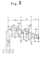
- Fig. 2 is.a view illustrating an example of the mechanism of a horizontal articulated-type robot
- Fig. 3 is an external view of the same robot
- Fig. 4 is a block diagram showing the construction of the conventional apparatus.
- Fig. 2 is a view illustrating the mechanism of a horizontal articulated-type robot having a link L 1 of length l1, a link L 2 of length l 2 , and a hand H of length l 3 .
- the link L l is rotatable about an axis ⁇ 1 , the link L 2 about an axis ⁇ 2 , and the hand H about an axis ⁇ 3 .
- the torque T 3 of the hand H about the ⁇ 3 axis is obtained as follows:
- the coefficient A is expressed as follows:
- the distance S 3 from the distal end of hand H to the position of the center of gravity of the hand H when the hand is gripping a workpiece is calculated as follows:
- J 3yy obtained by expressing the inertia of the hand H about its center of gravity in a coordinate system fixed with respect to the hand H, is written as follows: However, when the hand H is not gripping a workpiece, Mw is made zero in each of the above equations.
- the torque T 1 of the link L 1 about the axis 8 1 is obtained as follows:
- Fig. 1 is a block diagram illustrating an example of a control system for a robot arm controlled by applying the apparatus of the present invention.
- Each servo CPU is connected to a main CPU a by a bus line and is capable of executing, on line, equations of motion necessary for control along each axis in accordance with a control signal from the main CPU.
- Inverters d l , d 2 control the currents of servomotors e 1 e 2 .
- a shared RAM b is connected between the main CPU a and each of the servo CPUs cl, c2.
- the plurality of servo CPU's c 1 , c 2 ... for controlling the loads driven about the axes ⁇ 1 , ⁇ 2. . . of the robot arms upon receiving a manipulator control command from the main CPU a are connected via a bus line f so as to be capable of accessing the RAM.
- the servomotors e 1 , e 2 are subjected to predetermined positioning control and current control by the servo CPUs c 1 , c 2 and inverters d l , d 2 , respectively.
- the aforementioned shared RAM b stores information about each axis.
- the RAM is capable of being accessed by the servo CPU c l , c 2 ... in order that the information may be read for the purpose of performing torque calculations.
- the shared RAM b has the following functions:
- a CRT/MDI g Also connected to the shared RAM b is a CRT/MDI g controlled by the operator so that the operator can confirm manipulator operation in the form of picture data. Hand and workpiece weight can be set in advance by the CRT/MDI g.
- the operator inputs the weight of the robot hand and the weight of a workpiece to the shared RAM b from the CRT/MDI g via the main CPU a.
- the main CP U a outputs position commands for the servomotors e l , e 2 ..., the robot arm starts to move and information relating to the load about each axis is stored in the shared RAM b .
- the servo CPUs cl , c 2 . . . read the information for the other axes out of the shared RAM b at a time when current loop control is not being controlled, calculate the non-linear torque T(8,8) on line in accordance with the Eqs. (1), (4) and (5), and perform feed-forward compensation with respect to the servo-control system.
- the operator can change the workpiece weight value and input the same as the occasion demands.
- a RAM capable of being accessed commonly by the servo CPUs controlling the respective servomotors is provided. Information about the other axes is fetched from the RAM and non-linear torque is calculated when a servo CPU is not performing current loop processing. As a result, current loop processing is not impededd and the servomotors can be controlled very accurately.
- the weight value of a workpiece gripped by the robot arm is modified, set and inputted to the servo CPUs at the required timing, and drive torque calculation necessary for servomotor control is performed. Accordingly, the operator is readily capable of dealing with a change in workpiece weight value, and the system can be readily modified in so far as processing for various workpieces is concerned. As a result, when the robot control apparatus of the invention is applied to a horizontal articulated-type robot, much more accurate positional control becomes possible and the robot can be controlled at high speed and in a highly precise manner.
Landscapes
- Engineering & Computer Science (AREA)
- Human Computer Interaction (AREA)
- Manufacturing & Machinery (AREA)
- Physics & Mathematics (AREA)
- General Physics & Mathematics (AREA)
- Automation & Control Theory (AREA)
- Computer Hardware Design (AREA)
- Microelectronics & Electronic Packaging (AREA)
- Numerical Control (AREA)
- Manipulator (AREA)
Abstract
Applications Claiming Priority (6)
| Application Number | Priority Date | Filing Date | Title |
|---|---|---|---|
| JP5643586A JPS62212806A (ja) | 1986-03-14 | 1986-03-14 | ロボツトア−ムの制御装置 |
| JP56435/86 | 1986-03-14 | ||
| JP5643486A JPS62212812A (ja) | 1986-03-14 | 1986-03-14 | ロボツトア−ムの制御装置 |
| JP61056433A JPH0766285B2 (ja) | 1986-03-14 | 1986-03-14 | ロボツトア−ムの制御装置 |
| JP56434/86 | 1986-03-14 | ||
| JP56433/86 | 1986-03-14 |
Publications (3)
| Publication Number | Publication Date |
|---|---|
| EP0260326A1 true EP0260326A1 (fr) | 1988-03-23 |
| EP0260326A4 EP0260326A4 (fr) | 1990-03-12 |
| EP0260326B1 EP0260326B1 (fr) | 1993-08-04 |
Family
ID=27295918
Family Applications (1)
| Application Number | Title | Priority Date | Filing Date |
|---|---|---|---|
| EP87901684A Expired - Lifetime EP0260326B1 (fr) | 1986-03-14 | 1987-03-14 | Controleur de robot |
Country Status (4)
| Country | Link |
|---|---|
| US (1) | US4873476A (fr) |
| EP (1) | EP0260326B1 (fr) |
| DE (1) | DE3786860T2 (fr) |
| WO (1) | WO1987005721A1 (fr) |
Cited By (4)
| Publication number | Priority date | Publication date | Assignee | Title |
|---|---|---|---|---|
| EP0415239A3 (en) * | 1989-08-30 | 1991-04-24 | Seiko Seiki Kabushiki Kaisha | A numerical control device for a grinding machine |
| DE4026413A1 (de) * | 1989-11-10 | 1991-05-16 | Mitsubishi Electric Corp | Positionier-steuervorrichtung |
| EP0333876A4 (en) * | 1987-09-19 | 1993-05-12 | Fanuc Ltd | Method of controlling robot depending upon load conditions |
| FR2704077A1 (fr) * | 1993-04-13 | 1994-10-21 | Audrand Armand | Commande numérique à contrôle d'axes par programmes différentiels. |
Families Citing this family (21)
| Publication number | Priority date | Publication date | Assignee | Title |
|---|---|---|---|---|
| JP2514669B2 (ja) * | 1987-10-14 | 1996-07-10 | ファナック株式会社 | サ―ボモ―タの制御方式 |
| JP2997270B2 (ja) * | 1988-01-19 | 2000-01-11 | ファナック株式会社 | 補間方法 |
| JPH01217605A (ja) * | 1988-02-26 | 1989-08-31 | Fanuc Ltd | 多軸多系統工作機械用数値制御装置 |
| US5252899A (en) * | 1988-03-09 | 1993-10-12 | Fanuc Ltd | Numerical control system |
| JPH02198783A (ja) * | 1989-01-23 | 1990-08-07 | Fanuc Ltd | 産業用ロボットの位置決め補正方式 |
| JP2521830B2 (ja) * | 1990-02-14 | 1996-08-07 | 川崎重工業株式会社 | 産業用ロボットの制御方法および装置 |
| DE4039771A1 (de) * | 1990-12-13 | 1992-06-17 | Juergen Heesemann | Maschinensteuerung |
| JP2716270B2 (ja) * | 1990-12-27 | 1998-02-18 | 株式会社日立製作所 | マニピュレ−タ |
| DE69316559T2 (de) * | 1992-12-03 | 1998-09-10 | Advanced Micro Devices Inc | Servoregelkreissteuerung |
| JP2574983B2 (ja) * | 1993-04-06 | 1997-01-22 | 本田技研工業株式会社 | マルチタスク制御システム |
| EP0640929A3 (fr) * | 1993-08-30 | 1995-11-29 | Advanced Micro Devices Inc | Communication interprocesseur via une MEV poste. |
| JP3327123B2 (ja) * | 1996-06-04 | 2002-09-24 | トヨタ自動車株式会社 | 作業用ロボットの統合制御システム |
| US6672174B2 (en) * | 2001-07-23 | 2004-01-06 | Fidelica Microsystems, Inc. | Fingerprint image capture device with a passive sensor array |
| US7038421B2 (en) * | 2003-06-17 | 2006-05-02 | International Business Machines Corporation | Method and system for multiple servo motor control |
| US8000837B2 (en) | 2004-10-05 | 2011-08-16 | J&L Group International, Llc | Programmable load forming system, components thereof, and methods of use |
| JP4256440B2 (ja) * | 2007-08-10 | 2009-04-22 | ファナック株式会社 | ロボットプログラム調整装置 |
| US20100188034A1 (en) * | 2009-01-23 | 2010-07-29 | Derek Young | Trainable Robot and Method of Training |
| JP2011108044A (ja) * | 2009-11-18 | 2011-06-02 | Fanuc Ltd | N個のロボットを同時に制御するロボット制御装置 |
| US10022861B1 (en) * | 2017-04-27 | 2018-07-17 | Engineering Services Inc. | Two joint module and arm using same |
| JP7207094B2 (ja) * | 2019-03-29 | 2023-01-18 | セイコーエプソン株式会社 | 水平多関節ロボット |
| JP2020163548A (ja) * | 2019-03-29 | 2020-10-08 | セイコーエプソン株式会社 | 水平多関節ロボットおよびロボットシステム |
Family Cites Families (15)
| Publication number | Priority date | Publication date | Assignee | Title |
|---|---|---|---|---|
| DE2656433C3 (de) * | 1976-12-14 | 1983-11-17 | Fraunhofer-Gesellschaft Zur Foerderung Der Angewandten Forschung E.V., 8000 Muenchen | Verfahren und Anordnung zur Regelung von Manipulatoen und industriellen Robotern |
| DE2852821B1 (de) * | 1978-12-07 | 1980-04-30 | Walter Reis Maschinenbau, 8753 Obernburg | Manipulator |
| CH637228A5 (fr) * | 1980-03-27 | 1983-07-15 | Willemin Machines Sa | Dispositif de commande d'une machine ou d'une installation. |
| JPS5769315A (en) * | 1980-10-13 | 1982-04-28 | Fanuc Ltd | Control system of industrial robot |
| US4409650A (en) * | 1981-03-04 | 1983-10-11 | Shin Meiwa Industry Co., Ltd. | Automatic position controlling apparatus |
| JPS5822412A (ja) * | 1981-08-04 | 1983-02-09 | Fanuc Ltd | 工業用ロボツト制御方式 |
| JPS5862706A (ja) * | 1981-10-09 | 1983-04-14 | Fanuc Ltd | 数値制御方式 |
| US4467436A (en) * | 1981-10-26 | 1984-08-21 | United States Robots, Inc. | Robot arm controller with common bus memory |
| JPS58223583A (ja) * | 1982-06-21 | 1983-12-26 | 三菱電機株式会社 | 産業用ロボツトの制御装置 |
| US4514814A (en) * | 1982-09-07 | 1985-04-30 | General Electric Company | Multi-processor axis control |
| KR900003637B1 (ko) * | 1982-11-26 | 1990-05-28 | 가부시기가이샤 히다찌 세이사꾸쇼 | 로보트의 동작제어장치 |
| JPS59153207A (ja) * | 1983-02-21 | 1984-09-01 | Mitsubishi Electric Corp | ロボツトの制御装置 |
| GB8324866D0 (en) * | 1983-09-16 | 1983-10-19 | Cambridge Electronic Ind | Control of robots |
| JPS60263206A (ja) * | 1984-06-11 | 1985-12-26 | Nissan Motor Co Ltd | マニピユレ−タの制御装置 |
| JP2971261B2 (ja) * | 1992-08-12 | 1999-11-02 | 三菱重工業株式会社 | 板材の圧延方法 |
-
1987
- 1987-03-14 WO PCT/JP1987/000162 patent/WO1987005721A1/fr not_active Ceased
- 1987-03-14 EP EP87901684A patent/EP0260326B1/fr not_active Expired - Lifetime
- 1987-03-14 DE DE87901684T patent/DE3786860T2/de not_active Expired - Fee Related
- 1987-03-14 US US07/110,727 patent/US4873476A/en not_active Expired - Lifetime
Cited By (6)
| Publication number | Priority date | Publication date | Assignee | Title |
|---|---|---|---|---|
| EP0333876A4 (en) * | 1987-09-19 | 1993-05-12 | Fanuc Ltd | Method of controlling robot depending upon load conditions |
| EP0415239A3 (en) * | 1989-08-30 | 1991-04-24 | Seiko Seiki Kabushiki Kaisha | A numerical control device for a grinding machine |
| US5105137A (en) * | 1989-08-30 | 1992-04-14 | Seiko Seiki Kabushiki Kaisha | Numerical control device for a grinding machine |
| DE4026413A1 (de) * | 1989-11-10 | 1991-05-16 | Mitsubishi Electric Corp | Positionier-steuervorrichtung |
| DE4026413C2 (de) * | 1989-11-10 | 2000-05-31 | Mitsubishi Electric Corp | Positionier-Steuervorrichtung |
| FR2704077A1 (fr) * | 1993-04-13 | 1994-10-21 | Audrand Armand | Commande numérique à contrôle d'axes par programmes différentiels. |
Also Published As
| Publication number | Publication date |
|---|---|
| WO1987005721A1 (fr) | 1987-09-24 |
| DE3786860T2 (de) | 1993-11-11 |
| DE3786860D1 (de) | 1993-09-09 |
| EP0260326B1 (fr) | 1993-08-04 |
| US4873476A (en) | 1989-10-10 |
| EP0260326A4 (fr) | 1990-03-12 |
Similar Documents
| Publication | Publication Date | Title |
|---|---|---|
| US4873476A (en) | Robot control apparatus for controlling a manipulator through a robot arm having a plurality of axes | |
| US4621332A (en) | Method and apparatus for controlling a robot utilizing force, position, velocity, spring constant, mass coefficient, and viscosity coefficient | |
| US4594671A (en) | Velocity method of controlling industrial robot actuators | |
| US4542471A (en) | Robot control system for presetting limit values corresponding to limits of deviation | |
| US4475160A (en) | Method of sensing abnormal condition in robot control apparatus | |
| US4906907A (en) | Robot system | |
| EP0159131B1 (fr) | Système d'entraînement pour un appareil déplaçable | |
| US5742138A (en) | Control method for servo system with adjustable softness in rectangular coordinate system | |
| US6140788A (en) | Method and system for controlling robot | |
| US5587638A (en) | Flexible servo control method capable of specifying flexibility on working coordinates | |
| EP0240570B1 (fr) | Systeme de commande d'acceleration et de deceleration pour robots a articulation horizontale | |
| EP0271590B1 (fr) | Dispositif de commande de robot | |
| EP0353305A1 (fr) | Robot industriel capable de modifier automatiquement ses conditions de fonctionnement selon sa position d'installation | |
| JPS62251901A (ja) | 多軸ロボツトの経路制御装置 | |
| EP0207168A1 (fr) | Systeme de commande de l'entrainement de servomoteurs | |
| Kikuchi et al. | Heavy parts assembly by coordinative control of robot and balancing manipulator | |
| JPH10244482A (ja) | ロボット制御装置 | |
| JPH0766285B2 (ja) | ロボツトア−ムの制御装置 | |
| JPS62212806A (ja) | ロボツトア−ムの制御装置 | |
| JPS62212812A (ja) | ロボツトア−ムの制御装置 | |
| JP2635776B2 (ja) | マスタ・スレーブ形マニピュレータ | |
| JPS61159390A (ja) | 産業用ロボツトの制御方法 | |
| JPS638912A (ja) | ロボツトの制御方式 | |
| JPS6160447B2 (fr) | ||
| JPS62212802A (ja) | ロボツトア−ムの制御装置 |
Legal Events
| Date | Code | Title | Description |
|---|---|---|---|
| PUAI | Public reference made under article 153(3) epc to a published international application that has entered the european phase |
Free format text: ORIGINAL CODE: 0009012 |
|
| 17P | Request for examination filed |
Effective date: 19871012 |
|
| AK | Designated contracting states |
Kind code of ref document: A1 Designated state(s): DE FR GB |
|
| A4 | Supplementary search report drawn up and despatched |
Effective date: 19900312 |
|
| 17Q | First examination report despatched |
Effective date: 19911220 |
|
| GRAA | (expected) grant |
Free format text: ORIGINAL CODE: 0009210 |
|
| AK | Designated contracting states |
Kind code of ref document: B1 Designated state(s): DE FR GB |
|
| PG25 | Lapsed in a contracting state [announced via postgrant information from national office to epo] |
Ref country code: FR Effective date: 19930804 |
|
| REF | Corresponds to: |
Ref document number: 3786860 Country of ref document: DE Date of ref document: 19930909 |
|
| EN | Fr: translation not filed | ||
| PG25 | Lapsed in a contracting state [announced via postgrant information from national office to epo] |
Ref country code: GB Effective date: 19940314 |
|
| PLBE | No opposition filed within time limit |
Free format text: ORIGINAL CODE: 0009261 |
|
| STAA | Information on the status of an ep patent application or granted ep patent |
Free format text: STATUS: NO OPPOSITION FILED WITHIN TIME LIMIT |
|
| 26N | No opposition filed | ||
| GBPC | Gb: european patent ceased through non-payment of renewal fee |
Effective date: 19940314 |
|
| PGFP | Annual fee paid to national office [announced via postgrant information from national office to epo] |
Ref country code: DE Payment date: 20010306 Year of fee payment: 15 |
|
| PG25 | Lapsed in a contracting state [announced via postgrant information from national office to epo] |
Ref country code: DE Free format text: LAPSE BECAUSE OF NON-PAYMENT OF DUE FEES Effective date: 20021001 |