EP0260332A1 - Wäschetrockengestell - Google Patents
Wäschetrockengestell Download PDFInfo
- Publication number
- EP0260332A1 EP0260332A1 EP86112736A EP86112736A EP0260332A1 EP 0260332 A1 EP0260332 A1 EP 0260332A1 EP 86112736 A EP86112736 A EP 86112736A EP 86112736 A EP86112736 A EP 86112736A EP 0260332 A1 EP0260332 A1 EP 0260332A1
- Authority
- EP
- European Patent Office
- Prior art keywords
- support element
- support arms
- support
- drying rack
- central
- Prior art date
- Legal status (The legal status is an assumption and is not a legal conclusion. Google has not performed a legal analysis and makes no representation as to the accuracy of the status listed.)
- Granted
Links
Images


Classifications
-
- D—TEXTILES; PAPER
- D06—TREATMENT OF TEXTILES OR THE LIKE; LAUNDERING; FLEXIBLE MATERIALS NOT OTHERWISE PROVIDED FOR
- D06F—LAUNDERING, DRYING, IRONING, PRESSING OR FOLDING TEXTILE ARTICLES
- D06F57/00—Supporting means, other than simple clothes-lines, for linen or garments to be dried or aired
- D06F57/12—Supporting means, other than simple clothes-lines, for linen or garments to be dried or aired specially adapted for attachment to walls, ceilings, stoves, or other structures or objects
-
- D—TEXTILES; PAPER
- D06—TREATMENT OF TEXTILES OR THE LIKE; LAUNDERING; FLEXIBLE MATERIALS NOT OTHERWISE PROVIDED FOR
- D06F—LAUNDERING, DRYING, IRONING, PRESSING OR FOLDING TEXTILE ARTICLES
- D06F57/00—Supporting means, other than simple clothes-lines, for linen or garments to be dried or aired
- D06F57/08—Folding stands
Definitions
- the present invention relates to a laundry drying rack with ropes, rods or the like arranged between parallel support arms for receiving the laundry to be dried according to the preamble of patent claim 1.
- a laundry drying rack of the generic type is known from DE-OS 23 32 998.
- this has a U-shaped rail to be fastened to a wall, at the two ends of which a support arm covered with a plurality of lines is pivotably mounted. Since the two support arms can be pivoted in opposite directions from the position of use, where they protrude essentially perpendicularly from the U-rail, into a folded-in rest position, there is the disadvantage of the clothesline sagging when folded.
- the purpose of that tumble dryer is to avoid this disadvantage, by the fact that the two arms can first be folded up so that the clothes lines run in a vertical plane common to the arms. Subsequent folding of the arms then, under the action of gravity, leads to the washing lines being taken up in the cavity of the U-profile.
- Such a dryer is only suitable for stationary Ge need; in particular, as can be seen from the aforementioned DE-OS, it must be attached to a wall.
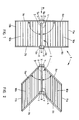
- the laundry drying rack generally designated 1, has an elongated, central support element 2, which in the example is formed by two aluminum profiles 3 and 4 running parallel to one another. At the two free ends of the profiles 3 and 4, connecting elements 5a, 5b and 6a, 6b, for example made of plastic, are attached, which have lateral, projecting tabs 7. Two adjacent of these tabs 7 are through Means, not shown, are connected to one another so that the connecting elements 5a and 5b or 6a and 6b can be pivoted relative to one another (see FIGS. 4-6).
- the connecting elements 5a, 5b, 6a and 6b also serve to receive a respective support arm 8a, 8b, 9a and 9b and to connect them to the central support element 2. Between the pairs of support arms 8a, 8b and the pairs of support arms 9a, 9b, a washing line 10a or 10b is stretched; there is no need to go into details in this connection, since this is known prior art.
- the axis X essentially coincides with the central axis of the central support element 2 or runs symmetrically between the two profiles 3 and 4.
- the two dryer halves, each formed from two support arms and the laundry ropes stretched between them, can be extended from one position ( Fig. 1 or Fig. 4) are continuously brought into a folded position (Fig. 6) via a partially folded position (Fig. 5).
- the support arms 8a, 8b, 9a and 9b are pivotally received in the associated connecting elements 5a, 5b, 6a and 6c; the pivoting takes place about an axis Y, which runs perpendicular to the axis X already mentioned.
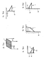
- the arrangement is such that, for example, rod-shaped connecting members 11a and 11b, which are also pivotably attached to the free ends of the support arms, in such a way that a pair of support arms 8a, 8b or 9a, 9b) in each case in the form of a parallelogram from an extended position according to FIG. 1 , where the support arms are substantially perpendicular to the support element 2, can be brought into a fully retracted position (FIG. 3) via a partially folded position (FIG. 2).
- the pivoting of the support arms 8a, 8b and 9a, 9b takes place in each case about the assigned axis Y.
- a laundry drying rack 1 folded and folded in this way requires very little space for storage, since the shape of an elongated body is approximately taken up by bringing the support arms 8a, 8b and 9a, 9b into one position in which they run at least approximately parallel to the central support element 2.
- the two connecting elements 5a, 5b and 6a, 6b which interact in each case, are pivotally connected to one another by suitable means such that they can be locked in any pivot position. This can be done, for example, by means of clamping screws or other known means, which need not be discussed in more detail here. Locking means (not shown) can also be provided be that fix the arms 8a, 8b or 9a, 9b in their position, be it unfolded or be it folded in.
- the clothes drying rack 1 can be set up over a bath tub 12, the ends of the support arms 8 and 9 each being provided with anti-slip and / or fork-like support members 13.
- the frame 1 is supported on the edge of the bath tub 12 and on the wall 14 and is in the unfolded position according to FIG. 1.
- the frame 1 can also be used over a bath tub 12 in a partially folded position, as shown in FIG. 9 ; the support members 13 lie on opposite upper edges of the bath tub 12.
- a stand 14 can be provided in order to set up the frame 1 freely.
- a central column stand with a foot is also suitable.
- 11 and 12 show two ways of attaching the frame 1 to the parapet 15 of a balcony.
- hook-like anchoring members (not shown) are provided, into which the connecting member 11a engages at the end of the arms 8.
- the arms 9, however, are supported on the balcony parapet 16 via an intermediate member 18.
- FIG. 12 the frame 1 is again in an unfolded state, the ends of the arms 8 being fastened to the upper edge of the balcony parapet 16 by means of clip-like elements 19.
- a support 17, which engages the central support element 2 ensures that the frame 1 is in a stable position.
- FIG. 14 A corresponding way of use on a wall 20, above a radiator 21, is shown in FIG. 14: the frame 1 is here almost completely unfolded and is supported on the wall 20 and on the floor.
- the frame 1 can also be attached to the outer wall 21 of a caravan, cf. Fig. 15.
- the laundry drying rack 1 can also be converted into a balcony table, in that it is fastened to the inside of a balcony railing 16 in a largely folded state, using an intermediate member 18, and provided with a table top 22. 17 shows that the laundry drying rack 1 can also be suspended by means of ropes or wires 23, the rack preferably being in the fully unfolded state.
Landscapes
- Engineering & Computer Science (AREA)
- Textile Engineering (AREA)
- Accessory Of Washing/Drying Machine, Commercial Washing/Drying Machine, Other Washing/Drying Machine (AREA)
- Drying Of Solid Materials (AREA)
- Holders For Apparel And Elements Relating To Apparel (AREA)
- Agricultural Chemicals And Associated Chemicals (AREA)
- Invalid Beds And Related Equipment (AREA)
Abstract
Description
- Die vorliegende Erfindung bezieht sich auf ein Wäschetrockengestell mit zwischen parallelen Tragarmen angeordneten Seilen, Stäben oder dgl. zur Aufnahme der zu trocknenden Wäsche nach dem Oberbegriff des Patentanspruchs 1.
- Ein Wäschetrockengestell der gattungsgemässen Art ist aus der DE-OS 23 32 998 bekannt. Dieses weist als langgestrecktes Tragelement eine an einer Wand zu befestigende U-förmige Schiene auf, an deren beiden Enden je ein mit einer Mehrzahl von Leinen bespannter Tragarm schwenkbar gelagert ist. Da die beiden Tragarme von der Gebrauchsstellung, wo sie im wesentlichen senkrecht von der U-Schiene abstehen, gegensinnig in eine eingeklappte Ruhestellung zu verschwenken sind, besteht der Nachteil des Durchhängens der Wäscheleine beim Zusammenklappen. Jener Wäschetrockner stellt sich die Aufgabe, diesen Nachteil zu vermeiden, und zwar dadurch, dass die beiden Arme zuerst hochgeklappt werden können, damit die Wäscheleinen in einer vertikalen, mit den Armen gemeinsamen Ebene verlaufen. Ein anschliessendes Einklappen der Arme führt dann, unter Wirkung der Schwerkraft, dazu, dass die Wäscheleinen im Hohlraum des U-Profils aufgenommen werden.
- Ein solcher Wäschetrockner eignet sich nur für stationären Ge brauch; insbesondere muss er, wie aus der genannten DE-OS hervorgeht, an einer Wand befestigt werden.
- Es ist die Aufgabe der vorliegenden Erfindung, ein Wäschetrokkengestell der gattungsgemässen Art so weiterzubilden, dass es vielfältiger eingesetzt werden kann, insbesondere nicht gezwungenermassen an einer Wand befestigt werden muss, sondern auch anderweitig, z.B. freistehend oder auf einem Ständer eingesetzt werden kann, dass es ferner eine vergrösserte Wäscheaufnahmekapazität besitzt, und schliesslich, dass es bei Nichtgebrauch auf kleinstem Raum aufbewahrt werden kann.
- Gemäss der Erfindung wird diese Aufgabe durch die Kombination der im Patentanspruch 1 genannten Merkmale gelöst. Weiterbildungen des Erfindungsgegenstandes und besondere Ausführungsformen sind in den abhängigen Patentansprüchen 2 bis 6 definiert.
- Im folgenden wird ein Ausführungsbeispiel des Erfindungsgegenstandes, unter Bezugnahme auf die beiliegenden Zeichnungen, näher erläutert. Im einzelnen zeigen:
- Fig. 1 eine schematische Ansicht von oben, in ausgeklapptem, ungefaltetem Zustand;
- Fig. 2 eine schematische Ansicht von oben, in teilweise eingeklapptem, ungefaltetem Zustand;
- Fig. 3 eine Schematische Ansicht von oben, in vollständig eingeklapptem, ungefaltetem Zustand;
- Fig. 4 eine schematische Seitenansicht in Richtung des Pfeiles P1 gemäss Fig. 1;
- Fig. 5 eine schematische Seitenansicht, ähnlich Fig. 4, aber in teilweise gefaltetem Zustand;
- Fig. 6 eine schematische Seitenansicht, ähnlich Fig. 4, aber in vollständig gefaltetem Zustand;
- Fig. 7 eine schematische Seitenansicht, ähnlich Fig. 4, aber in vollständig gefaltetem und vollständig eingeklapptem Zustand, und
- Fig. 8 - 17 schematische Ansichten des Erfindungsgegenstandes zur Veranschaulichung verschiedener Verwendungsmöglichkeiten.
- Das generell mit 1 bezeichnete Wäschetrockengestell besitzt ein langgestrecktes, zentrales Tragelement 2, das im Beispielsfall durch zwei parallel nebeneinander verlaufende Aluminiumprofile 3 und 4 gebildet ist. An den beiden freien Enden der Profile 3 und 4 sind jeweils Verbindungselemente 5a, 5b bzw. 6a, 6b, z.B. aus Kunststoff angebracht, welche seitliche, abstehende Laschen 7 besitzen. Je zwei benachbarte dieser Laschen 7 sind durch nicht dargestellte Mittel miteinander verbunden, sodass die Verbindungselemente 5a und 5b bzw. 6a und 6b gegeneinander verschwenkt werden können (vgl. Fig. 4 - 6).
- Die Verbindungselemente 5a, 5b, 6a und 6b dienen ferner dazu, je einen Tragarm 8a, 8b, 9a und 9b aufzunehmen und diese mit dem zentralen Tragelement 2 zu verbinden. Zwischen den Tragarm-Paaren 8a, 8b und den Tragarm-Paaren 9a, 9b ist jeweils eine Wäscheleine 10a bzw. 10b gespannt; auf Einzelheiten braucht in diesem Zusammenhang nicht eingegangen zu werden, da dies bekannter Stand der Technik ist.
- Das Tragarm-Paar 8, gebildet aus den beiden Tragarmen 8a und 8b, ist gegenüber dem Tragarm-Paar 9, gebildet aus den beiden Tragarmen 9a und 9b, um ein Achse X schwenkbar. Die Achse X fällt im wesentlichen mit der Mittelachse des zentralen Tragelementes 2 zusammen bzw. verläuft symmetrisch zwischen den beiden Profilen 3 und 4. Damit können die beiden Wäschetrockner-Hälften, gebildet aus jeweils zwei Tragarmen und den dazwischen gespannten Wäscheseilen, von einer auseinandergefalteten Stellung (Fig. 1 bzw. Fig. 4) kontinuierlich über eine teilweise zusammengefaltete Stellung (Fig. 5) in eine zusammengefaltete Stellung (Fig. 6) gebracht werden.
- Ausserdem sind die Tragarme 8a, 8b, 9a und 9b schwenkbar in den zugeordneten Verbindungselementen 5a, 5b, 6a und 6c aufgenommen; die Verschwenkung erfolgt dabei um jeweils eine Achse Y, die senkrecht zur bereits erwähnten Achse X verläuft. Die Anordnung ist dabei so getroffen, z.B. durch ebenfalls schwenkbar an den freien Enden der Tragarme angebrachte, stabförmige Verbindungsglieder 11a und 11b, dass ein Tragarm-Paar 8a,8b bzw. 9a,9b) jeweils parallelogrammartig zusammen von einer ausgeklappten Stellung gemäss Fig. 1, wo die Tragarme im wesentlichen senkrecht zum Tragelement 2 stehen, über eine teilweise eingeklappte Stellung (Fig. 2) in eine vollständig eingeklappte Stellung (Fig . 3) gebracht werden können. Die Verschwenkung der Tragarme 8a, 8b bzw. 9a, 9b erfolgt dabei jeweils um die zugeordnete Achse Y.
- Wie aus Fig. 3 bzw. 7 ersichtlich ist, erfordert ein derart zusammengefaltetes und eingeklapptes Wäschetrockengestell 1 nur sehr wenig Platz zwecks Aufbewahrung, da annähernd die Gestalt eines langgestreckten Körpers eingenommen wird, indem die Tragarme 8a, 8b sowie 9a, 9b in eine Lage gebracht werden, in der Sie zumindest annähernd parallel zum zentralen Tragelement 2 verlaufen.
- Es versteht sich, dass die beiden jeweils zusammenwirkenden Verbindungselemente 5a, 5b bzw. 6a, 6b mit geeigneten Mitteln so schwenkbar miteinander verbunden sind, dass ein Feststellen in einer beliebigen Schwenkposition ermöglicht ist. Dies kann beispielsweise durch Klemmschrauben oder andere, bekannte Mittel erfolgen, auf die hier nicht näher eingegangen werden muss. Ebenso können Arretiermittel (nicht dargestellt) vorgesehen sein, die die Arme 8a, 8b bzw. 9a, 9b in ihrer Position, sei es ausgeklappt, sei es eingeklappt, fixieren.
- Die Verwendungsmöglichkeiten des erfindungsgemässen Wäschetrokkengestells sind ausgesprochen vielfältig. Gemäss Fig. 8 kann das Wäschetrockengestell 1 über einer Badewanne 12 aufgestellt werden, wobei die Enden der Tragarme 8 und 9 jeweils mit rutschhemmenden und/oder gabelartigen Stützorganen 13 versehen sein können. Das Gestell 1 stützt sich dabei am Rand der Badewanne 12 und an der Wand 14 ab und befindet sich in der auseinandergefalteten Stellung gemäss Fig. 1. Auch in teilweise zusammengefalteter Stellung kann das Gestell 1 über einer Badewanne 12 verwendet werden, wie Fig. 9 zeigt; die Stützorgane 13 liegen dabei auf gegenüberliegenden Oberkanten der Badewanne 12 auf.
- Gemäss Fig. 10 kann ein Ständer 14 vorgesehen werden, um das Gestell 1 frei aufzustellen. Es versteht sich, dass sich im Gegensatz zur zeichnerischen Darstellung ein zentraler Säulenständer mit Fuss ebenso gut eignet. Die Fig. 11 und 12 zeigen zwei Möglichkeiten, das Gestell 1 an der Brüstung 15 eines Balkons anzubringen. Im Fall der Fig. 11, wo sich das Gestell 1 in weitgehend zusammengefaltetem Zustand befindet, sind (nicht dargestellte) hakenartige Verankerungsglieder vorgesehen, in die das Verbindungsglied 11a am Ende der Arme 8 eingreift. Die Arme 9 hingegen stützen sich über ein Zwischenglied 18 an der Balkonbrüstung 16 ab. Gemäss Fig. 12 ist das Gestell 1 wiederum in auseinandergefaltetem Zustand, wobei die Enden der Arme 8 mittels klammerartiger Elemente 19 an der Oberkante der Balkonbrüstung 16 befestigt sind. Eine Stütze 17, die am zentralen Tragelement 2 angreift, sorgt für eine stabile Lage des Gestells 1.
- Ähnlich wie in Fig. 11 gezeigt kann die Befestigung des Gestells 1 auch an einer Wand 20, z.B. über einem Heizungsradiator 21 erfolgen, wie dies in Fig. 13 verdeutlicht ist. Hier findet auch wieder ein Zwischenglied 18 Verwendung. Eine entsprechende Verwendungsweise an einer Wand 20, über einem Radiator 21, zeigt Fig. 14: Das Gestell 1 ist hier nahezu vollständig auseinandergefaltet und stützt sich an der Wand 20 sowie auf dem Fussboden ab. Anstatt an einer Balkonbrüstung 16 kann die Befestigung des Gestells 1 auch an der Aussenwand 21 eines Wohnwagens erfolgen, vgl. Fig. 15.
- Das Wäschetrockengestell 1 lässt sich gemäss Fig. 16 aber auch als Balkontisch umfunktionieren, indem es in weitgehend zusammengefaltetem Zustand an der Innenseite einer Balkonbrüstung 16, unter Verwendung eines Zwischengliedes 18, befestigt und mit einer Tischplatte 22 versehen wird. Die Fig. 17 lässt erkennen, dass das Wäschetrockengestell 1 auch mittels Seilen oder Drähten 23 aufgehängt werden kann, wobei sich das Gestell vorzugsweise in voll auseinandergefaltetem Zustand befindet.
- Vorstehend wurden nur einige Verwendungsbeispiele gegeben; die Möglichkeiten zur Verwendung des erfindungsgemässen Wäschetrockengestells sind nahezu unbegrenzt. Dabei darf nicht aus den Augen verloren werden, dass sich das erfindungsgemässe Wäschegestell stets leicht und schnell zusammenklappen lässt, um als schmales, längliches Gebilde gemäss Fig. 3 und 7 im kleinsten Schrank Platz zu finden.
Claims (6)
- Es ist ein zentrales Tragelement (2) vorgesehen, welches im Bereich seiner beiden, freien Enden je zwei Tragarme (8a, 8b und 9a, 9b) trägt, so dass zwei Tragarm-Paare gebildet sind;
- jedes der beiden am zentralen Tragelement (2) gelagerten Tragarm-Paare ist um die Mittelachse (X) des Tragelementes verschwenkbar und feststellbar;
- die Tragarme (8a, 8b bzw. 9a, 9b) sind paarweise von einer ausgeklappten Stellung, in der sie mit dem zentralen Tragelement (2) einen Winkel von zumindest annähernd 90° einschliessen, in eine eingeklappte Stellung verschwenkbar, in der sie zumindest annähernd parallel zum zentralen Tragelement (2) verlaufen.
Priority Applications (5)
| Application Number | Priority Date | Filing Date | Title |
|---|---|---|---|
| EP86112736A EP0260332B1 (de) | 1986-09-15 | 1986-09-15 | Wäschetrockengestell |
| AT86112736T ATE70576T1 (de) | 1986-09-15 | 1986-09-15 | Waeschetrockengestell. |
| DE8686112736T DE3683051D1 (en) | 1986-09-15 | 1986-09-15 | Waeschetrockengestell. |
| US07/089,534 US4739888A (en) | 1986-09-15 | 1987-08-26 | Clothes drying apparatus |
| JP62219009A JPS6371295A (ja) | 1986-09-15 | 1987-09-01 | 衣服乾燥器具 |
Applications Claiming Priority (1)
| Application Number | Priority Date | Filing Date | Title |
|---|---|---|---|
| EP86112736A EP0260332B1 (de) | 1986-09-15 | 1986-09-15 | Wäschetrockengestell |
Publications (2)
| Publication Number | Publication Date |
|---|---|
| EP0260332A1 true EP0260332A1 (de) | 1988-03-23 |
| EP0260332B1 EP0260332B1 (de) | 1991-12-18 |
Family
ID=8195416
Family Applications (1)
| Application Number | Title | Priority Date | Filing Date |
|---|---|---|---|
| EP86112736A Expired - Lifetime EP0260332B1 (de) | 1986-09-15 | 1986-09-15 | Wäschetrockengestell |
Country Status (5)
| Country | Link |
|---|---|
| US (1) | US4739888A (de) |
| EP (1) | EP0260332B1 (de) |
| JP (1) | JPS6371295A (de) |
| AT (1) | ATE70576T1 (de) |
| DE (1) | DE3683051D1 (de) |
Cited By (6)
| Publication number | Priority date | Publication date | Assignee | Title |
|---|---|---|---|---|
| GB2302801A (en) * | 1995-07-06 | 1997-02-05 | David Murphy | Detachable copyholder for VDU screen |
| GB2303298A (en) * | 1995-07-15 | 1997-02-19 | David Murphy | Detachable copyholder for VDU screen |
| EP1029966A1 (de) * | 1999-02-17 | 2000-08-23 | Hailo-Werk Rudolf Loh GmbH & Co. KG | Wäschetrockner |
| WO2004018761A1 (de) * | 2002-08-23 | 2004-03-04 | Wuester Heinrich | Wäschetrockner |
| US6951064B2 (en) | 2002-08-23 | 2005-10-04 | Wuester Heinrich | Clothes drier |
| WO2011119744A3 (en) * | 2010-03-24 | 2012-02-23 | Douglas Lowell Raddatz | Drying rack |
Families Citing this family (10)
| Publication number | Priority date | Publication date | Assignee | Title |
|---|---|---|---|---|
| USD326963S (en) | 1989-10-10 | 1992-06-16 | Liz Claiborne, Inc. | Upright display stand and backdrop for displaying retail merchandise |
| DE4432332C1 (de) * | 1994-09-10 | 1996-05-15 | Tomasz Bachorski | Zusammenklappbares Wäschetrockengestell |
| US5711437A (en) * | 1996-08-30 | 1998-01-27 | Flickinger; Mark C. | Swinging frame clothesline |
| GB0002440D0 (en) * | 2000-02-04 | 2000-03-22 | Hills Industries Ltd | Improvements relating to folding rack driers |
| US6382434B1 (en) | 2001-04-04 | 2002-05-07 | Keith E. Silberg | Compact foldable merchandising display rack |
| US7036670B2 (en) * | 2003-01-08 | 2006-05-02 | Peter Ar-Fu Lam | Cloth drying apparatus |
| US7789251B1 (en) * | 2008-03-19 | 2010-09-07 | John R Clark | A-frame shelving |
| US20110139732A1 (en) * | 2009-12-11 | 2011-06-16 | Cabanban Reynaldo | Refrigerator placemat holder |
| GB201103310D0 (en) * | 2011-02-28 | 2011-04-13 | Quinn Luke | Ultra airer |
| US9955782B2 (en) * | 2016-04-01 | 2018-05-01 | James S Rue | Art panel rack |
Citations (4)
| Publication number | Priority date | Publication date | Assignee | Title |
|---|---|---|---|---|
| DE328816C (de) * | 1919-10-10 | 1920-11-05 | Max Feuerabend | Zusammenlegbarer Waeschetrockner |
| GB167901A (en) * | 1920-06-03 | 1921-08-25 | Caroline Maud Mary Williams | Means for supporting garments while being aired in front of a gas or other fire or electric heater |
| US1968644A (en) * | 1933-04-07 | 1934-07-31 | Absalom S Hickerson | Rack |
| DE1585580A1 (de) * | 1966-11-23 | 1971-04-01 | Bremshey & Co | Abnehmbarer Fuss fuer Waeschetrockner |
Family Cites Families (5)
| Publication number | Priority date | Publication date | Assignee | Title |
|---|---|---|---|---|
| US886116A (en) * | 1907-07-05 | 1908-04-28 | Dwight W Custer | Garment-hanger. |
| US1545072A (en) * | 1923-01-02 | 1925-07-07 | Milo L Stearns | Clothesrack |
| US1628936A (en) * | 1926-03-08 | 1927-05-17 | Joseph E Cardarelle | Drying rack for bathtubs |
| NL270498A (de) * | 1960-10-22 | |||
| DE2922763A1 (de) * | 1979-06-05 | 1980-12-11 | Leifheit International | Waeschetrockner |
-
1986
- 1986-09-15 AT AT86112736T patent/ATE70576T1/de not_active IP Right Cessation
- 1986-09-15 EP EP86112736A patent/EP0260332B1/de not_active Expired - Lifetime
- 1986-09-15 DE DE8686112736T patent/DE3683051D1/de not_active Expired - Lifetime
-
1987
- 1987-08-26 US US07/089,534 patent/US4739888A/en not_active Expired - Fee Related
- 1987-09-01 JP JP62219009A patent/JPS6371295A/ja active Pending
Patent Citations (4)
| Publication number | Priority date | Publication date | Assignee | Title |
|---|---|---|---|---|
| DE328816C (de) * | 1919-10-10 | 1920-11-05 | Max Feuerabend | Zusammenlegbarer Waeschetrockner |
| GB167901A (en) * | 1920-06-03 | 1921-08-25 | Caroline Maud Mary Williams | Means for supporting garments while being aired in front of a gas or other fire or electric heater |
| US1968644A (en) * | 1933-04-07 | 1934-07-31 | Absalom S Hickerson | Rack |
| DE1585580A1 (de) * | 1966-11-23 | 1971-04-01 | Bremshey & Co | Abnehmbarer Fuss fuer Waeschetrockner |
Cited By (10)
| Publication number | Priority date | Publication date | Assignee | Title |
|---|---|---|---|---|
| GB2302801A (en) * | 1995-07-06 | 1997-02-05 | David Murphy | Detachable copyholder for VDU screen |
| GB2303298A (en) * | 1995-07-15 | 1997-02-19 | David Murphy | Detachable copyholder for VDU screen |
| EP1029966A1 (de) * | 1999-02-17 | 2000-08-23 | Hailo-Werk Rudolf Loh GmbH & Co. KG | Wäschetrockner |
| DE19906536A1 (de) * | 1999-02-17 | 2000-08-24 | Loh Kg Hailo Werk | Wäschetrockner |
| DE19906536B4 (de) * | 1999-02-17 | 2005-02-17 | Carl Freudenberg Kg | Wäschetrocknersystem |
| WO2004018761A1 (de) * | 2002-08-23 | 2004-03-04 | Wuester Heinrich | Wäschetrockner |
| US6951064B2 (en) | 2002-08-23 | 2005-10-04 | Wuester Heinrich | Clothes drier |
| WO2011119744A3 (en) * | 2010-03-24 | 2012-02-23 | Douglas Lowell Raddatz | Drying rack |
| CN102822408A (zh) * | 2010-03-24 | 2012-12-12 | 道格拉斯·洛厄尔·拉达茨 | 干燥架 |
| CN102822408B (zh) * | 2010-03-24 | 2016-03-30 | 道格拉斯·洛厄尔·拉达茨 | 干燥架 |
Also Published As
| Publication number | Publication date |
|---|---|
| JPS6371295A (ja) | 1988-03-31 |
| EP0260332B1 (de) | 1991-12-18 |
| DE3683051D1 (en) | 1992-01-30 |
| US4739888A (en) | 1988-04-26 |
| ATE70576T1 (de) | 1992-01-15 |
Similar Documents
| Publication | Publication Date | Title |
|---|---|---|
| EP0260332A1 (de) | Wäschetrockengestell | |
| DE60212335T2 (de) | Klapprahmenkonstruktion | |
| DE3500093A1 (de) | Leichter schutzschirm in zeltform mit einem aus tuch bestehenden dach | |
| DE69719977T2 (de) | Zusammenfaltbares zelt | |
| DE19906536B4 (de) | Wäschetrocknersystem | |
| DE6931267U (de) | Faltbares zimmergeruest. | |
| EP0457034B1 (de) | Wäscheständer mit Trocknungsrost | |
| EP1627948B1 (de) | Wäscheständer | |
| DE60035400T2 (de) | Geschirrkorb für eine Geschirrspülmaschine | |
| EP1743972B1 (de) | Schirmartiger Wäschetrockner mit Betätigungsvorrichtung | |
| DE102017126738B3 (de) | Wäscheständer zum Trocknen von Wäsche | |
| DE102011016701B4 (de) | Kuppelzelt | |
| EP0931871B1 (de) | Wäschetrocknungsgestell | |
| DE202021100420U1 (de) | Wäschetrocknungsgestell | |
| DE19604424C1 (de) | Korbträger für eine Wäschespinne | |
| DE102004043192B4 (de) | Tisch | |
| DE202016001297U1 (de) | Zusammenlegbare Leiter | |
| EP3712321B1 (de) | Wäscheständer zum trocknen von wäsche | |
| EP1508635A2 (de) | Schirmartiger Wäschetrockner | |
| EP2072655B1 (de) | Wäscheträger | |
| DE102006060730B4 (de) | Ausleger für eine Leiter oder ein Arbeitsgerüst | |
| DE7632570U1 (de) | Wäschetrockner | |
| DE4028532C2 (de) | ||
| DE20304663U1 (de) | Zusammenklappbarer Trockenständer | |
| DE2344947A1 (de) | Vertikales schalelement mit einer ueber seine vertikalebene vorspringenden konsole |
Legal Events
| Date | Code | Title | Description |
|---|---|---|---|
| PUAI | Public reference made under article 153(3) epc to a published international application that has entered the european phase |
Free format text: ORIGINAL CODE: 0009012 |
|
| AK | Designated contracting states |
Kind code of ref document: A1 Designated state(s): AT BE CH DE FR GB IT LI LU NL SE |
|
| 17P | Request for examination filed |
Effective date: 19880518 |
|
| 17Q | First examination report despatched |
Effective date: 19900706 |
|
| GRAA | (expected) grant |
Free format text: ORIGINAL CODE: 0009210 |
|
| AK | Designated contracting states |
Kind code of ref document: B1 Designated state(s): AT BE CH DE FR GB IT LI LU NL SE |
|
| PG25 | Lapsed in a contracting state [announced via postgrant information from national office to epo] |
Ref country code: IT Free format text: LAPSE BECAUSE OF FAILURE TO SUBMIT A TRANSLATION OF THE DESCRIPTION OR TO PAY THE FEE WITHIN THE PRESCRIBED TIME-LIMIT;WARNING: LAPSES OF ITALIAN PATENTS WITH EFFECTIVE DATE BEFORE 2007 MAY HAVE OCCURRED AT ANY TIME BEFORE 2007. THE CORRECT EFFECTIVE DATE MAY BE DIFFERENT FROM THE ONE RECORDED. Effective date: 19911218 Ref country code: FR Effective date: 19911218 Ref country code: NL Effective date: 19911218 Ref country code: BE Effective date: 19911218 Ref country code: GB Effective date: 19911218 Ref country code: SE Effective date: 19911218 |
|
| REF | Corresponds to: |
Ref document number: 70576 Country of ref document: AT Date of ref document: 19920115 Kind code of ref document: T |
|
| REF | Corresponds to: |
Ref document number: 3683051 Country of ref document: DE Date of ref document: 19920130 |
|
| EN | Fr: translation not filed | ||
| NLV1 | Nl: lapsed or annulled due to failure to fulfill the requirements of art. 29p and 29m of the patents act | ||
| GBV | Gb: ep patent (uk) treated as always having been void in accordance with gb section 77(7)/1977 [no translation filed] | ||
| PG25 | Lapsed in a contracting state [announced via postgrant information from national office to epo] |
Ref country code: LU Free format text: LAPSE BECAUSE OF NON-PAYMENT OF DUE FEES Effective date: 19920930 |
|
| PLBE | No opposition filed within time limit |
Free format text: ORIGINAL CODE: 0009261 |
|
| 26N | No opposition filed | ||
| PGFP | Annual fee paid to national office [announced via postgrant information from national office to epo] |
Ref country code: AT Payment date: 19970814 Year of fee payment: 12 |
|
| PG25 | Lapsed in a contracting state [announced via postgrant information from national office to epo] |
Ref country code: AT Free format text: LAPSE BECAUSE OF NON-PAYMENT OF DUE FEES Effective date: 19980915 |
|
| REG | Reference to a national code |
Ref country code: CH Ref legal event code: PL |
|
| REG | Reference to a national code |
Ref country code: CH Ref legal event code: AEN Free format text: DAS PATENT IST AUFGRUND DES WEITERBEHANDLUNGSANTRAGS VOM 06.05.1999 REAKTIVERT WORDEN. |
|
| PGFP | Annual fee paid to national office [announced via postgrant information from national office to epo] |
Ref country code: DE Payment date: 20010924 Year of fee payment: 16 |
|
| PG25 | Lapsed in a contracting state [announced via postgrant information from national office to epo] |
Ref country code: DE Free format text: LAPSE BECAUSE OF NON-PAYMENT OF DUE FEES Effective date: 20030401 |
|
| PGFP | Annual fee paid to national office [announced via postgrant information from national office to epo] |
Ref country code: CH Payment date: 20040830 Year of fee payment: 19 |
|
| PG25 | Lapsed in a contracting state [announced via postgrant information from national office to epo] |
Ref country code: LI Free format text: LAPSE BECAUSE OF NON-PAYMENT OF DUE FEES Effective date: 20050930 Ref country code: CH Free format text: LAPSE BECAUSE OF NON-PAYMENT OF DUE FEES Effective date: 20050930 |
|
| REG | Reference to a national code |
Ref country code: CH Ref legal event code: PL |