EP0260334B1 - Dispositif de vidage - Google Patents
Dispositif de vidage Download PDFInfo
- Publication number
- EP0260334B1 EP0260334B1 EP19860112745 EP86112745A EP0260334B1 EP 0260334 B1 EP0260334 B1 EP 0260334B1 EP 19860112745 EP19860112745 EP 19860112745 EP 86112745 A EP86112745 A EP 86112745A EP 0260334 B1 EP0260334 B1 EP 0260334B1
- Authority
- EP
- European Patent Office
- Prior art keywords
- discharge channel
- evacuation pipe
- discharge
- outlet opening
- wall portion
- Prior art date
- Legal status (The legal status is an assumption and is not a legal conclusion. Google has not performed a legal analysis and makes no representation as to the accuracy of the status listed.)
- Expired
Links
- 239000004744 fabric Substances 0.000 claims description 3
- 238000003306 harvesting Methods 0.000 description 4
- 238000011144 upstream manufacturing Methods 0.000 description 3
- 230000006978 adaptation Effects 0.000 description 2
- 241001124569 Lycaenidae Species 0.000 description 1
- 239000000463 material Substances 0.000 description 1
Images
Classifications
-
- A—HUMAN NECESSITIES
- A01—AGRICULTURE; FORESTRY; ANIMAL HUSBANDRY; HUNTING; TRAPPING; FISHING
- A01D—HARVESTING; MOWING
- A01D41/00—Combines, i.e. harvesters or mowers combined with threshing devices
- A01D41/12—Details of combines
- A01D41/1208—Tanks for grain or chaff
- A01D41/1217—Unloading mechanisms
Definitions
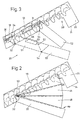
- an emptying pipe of the type mentioned at the outset is known (DE-B 1 457 938), which receives a pivotable bagging device with two outlet openings. If the bagging device is not to be used, it can be pivoted from an emptying position into an upper position in which the second outlet opening in the emptying pipe is closed via a bottom part of the bagging device and in which no more crop can be dispensed via the outlet openings of the bagging device.
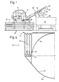
- 10 denotes a combine harvester which is equipped with a harvesting device 12, a driver's cab 14 and a collecting container 16.
- a mechanical linkage (not shown in the drawing, can be provided, which is connected at one end to the drain pipe 18 and at the other end to the discharge chute and which can be operated from the driver's cab 14 by means of a corresponding lever arm or a cable, in order to control the To pivot discharge channel 30 into the desired position.
Landscapes
- Life Sciences & Earth Sciences (AREA)
- Environmental Sciences (AREA)
- Threshing Machine Elements (AREA)
Claims (8)
Priority Applications (2)
| Application Number | Priority Date | Filing Date | Title |
|---|---|---|---|
| EP19860112745 EP0260334B1 (fr) | 1986-09-16 | 1986-09-16 | Dispositif de vidage |
| DE8686112745T DE3667128D1 (de) | 1986-09-16 | 1986-09-16 | Entleerungsvorrichtung. |
Applications Claiming Priority (1)
| Application Number | Priority Date | Filing Date | Title |
|---|---|---|---|
| EP19860112745 EP0260334B1 (fr) | 1986-09-16 | 1986-09-16 | Dispositif de vidage |
Publications (2)
| Publication Number | Publication Date |
|---|---|
| EP0260334A1 EP0260334A1 (fr) | 1988-03-23 |
| EP0260334B1 true EP0260334B1 (fr) | 1989-11-29 |
Family
ID=8195418
Family Applications (1)
| Application Number | Title | Priority Date | Filing Date |
|---|---|---|---|
| EP19860112745 Expired EP0260334B1 (fr) | 1986-09-16 | 1986-09-16 | Dispositif de vidage |
Country Status (2)
| Country | Link |
|---|---|
| EP (1) | EP0260334B1 (fr) |
| DE (1) | DE3667128D1 (fr) |
Families Citing this family (2)
| Publication number | Priority date | Publication date | Assignee | Title |
|---|---|---|---|---|
| DE102007036797A1 (de) * | 2007-08-03 | 2009-02-05 | Claas Kgaa Mbh | Erntemaschine mit Überladeeinrichtung |
| US7938613B2 (en) | 2009-04-15 | 2011-05-10 | Cnh America Llc | Grain unloading conveyor with directable spout and closure apparatus and system |
Family Cites Families (6)
| Publication number | Priority date | Publication date | Assignee | Title |
|---|---|---|---|---|
| US1615334A (en) * | 1925-09-21 | 1927-01-25 | Ji Case Threshing Machine Co | Combination harvester thrasher |
| DE960683C (de) * | 1954-08-15 | 1957-03-28 | Claas Maschf Gmbh Geb | Steuerklappe in der Spreuleitung eines Maehdreschers |
| DE1167091B (de) * | 1960-06-21 | 1964-04-02 | Guenther Claas | Maehdrescher mit aufliegendem kippbarem Korntank |
| DE1198109B (de) * | 1961-04-07 | 1965-08-05 | John Deere Lanz Ag | Vorrichtung zum Entleeren des Koernertankes von Maehdreschern |
| DE1457938B1 (de) * | 1962-01-05 | 1970-09-03 | Guenther Claas | Entleerungseinrichtung fuer einen Korntank eines Maehdreschers |
| DE1255378B (de) * | 1964-10-08 | 1967-11-30 | John Deere Lanz Ag | Koernerabsackvorrichtung an Maehdreschern |
-
1986
- 1986-09-16 DE DE8686112745T patent/DE3667128D1/de not_active Expired - Lifetime
- 1986-09-16 EP EP19860112745 patent/EP0260334B1/fr not_active Expired
Also Published As
| Publication number | Publication date |
|---|---|
| DE3667128D1 (de) | 1990-01-04 |
| EP0260334A1 (fr) | 1988-03-23 |
Similar Documents
| Publication | Publication Date | Title |
|---|---|---|
| DE60113359T2 (de) | Korntank einer Erntemaschine | |
| DE4232541C2 (de) | Hub- und Kippeinrichtung zur Entleerung eines Containers | |
| EP1564157B1 (fr) | Dispositif pour agrandir le volume des conteneurs | |
| EP3721695B1 (fr) | Engin d'abattage-façonnage et vis transporteuse correspondante | |
| DE2834729B2 (de) | Mähdrescher-Korntank | |
| EP2020176B1 (fr) | Moissonneuse dotée d'un dispositif de transbordement | |
| EP2020175B1 (fr) | Moissonneuse dotée d'un dispositif de transbordement réglable | |
| DE102011113684B3 (de) | Maispflücker mit Mitnehmervorrichtung | |
| DE10066348B4 (de) | Vorrichtung zur Erhöhung des Fassungsvermögens eines nach oben offenen Korntanks eines Mähdreschers und Korntank sowie Mähdrescher mit einer derartigen Vorrichtung | |
| DE4320565A1 (de) | Vorrichtung zur Erhöhung des Fassungsvermögens eines Behälterwandungen aufweisenden Behälters, Vorrichtung zu deren Betätigung und Verwendung | |
| EP0260334B1 (fr) | Dispositif de vidage | |
| DE10294970T5 (de) | Verteiler mit verstellbaren Verteilerflügeln | |
| EP0819371B1 (fr) | Trémie d'une machine de récolte | |
| DE19650617C2 (de) | Landwirtschaftliches Fahrzeug für die Fütterung von Tieren mit Silage | |
| DE20104426U1 (de) | Silage-Schneidzange | |
| DE20314002U1 (de) | Mischwagen | |
| EP4413846B1 (fr) | Machine de récolte | |
| DE29803468U1 (de) | Korntank für ein Getreide-Erntefahrzeug | |
| DE2731195A1 (de) | Ruebenerntemaschine | |
| EP4201188B1 (fr) | Appareil agricole | |
| EP0436068A1 (fr) | Méthode et dispositif pour le chargement, pauvre en poussière ou sans poussière, d'enceintes enfermées | |
| EP4062734A1 (fr) | Machine à planter pour plantes sarclées | |
| DE10047420C2 (de) | Bunker für mobile Lade- und Reinigungsmaschinen, insbesondere für Zuckerrüben | |
| DE19805399A1 (de) | Erntegutbergungsvorsatz | |
| EP0890301A1 (fr) | Châssis pivotant d'une tête de récolte de machines agricoles pour ramasser et convoyer des céréales |
Legal Events
| Date | Code | Title | Description |
|---|---|---|---|
| PUAI | Public reference made under article 153(3) epc to a published international application that has entered the european phase |
Free format text: ORIGINAL CODE: 0009012 |
|
| 17P | Request for examination filed |
Effective date: 19870807 |
|
| AK | Designated contracting states |
Kind code of ref document: A1 Designated state(s): DE FR GB IT |
|
| 17Q | First examination report despatched |
Effective date: 19880704 |
|
| ITF | It: translation for a ep patent filed | ||
| GRAA | (expected) grant |
Free format text: ORIGINAL CODE: 0009210 |
|
| AK | Designated contracting states |
Kind code of ref document: B1 Designated state(s): DE FR GB IT |
|
| GBT | Gb: translation of ep patent filed (gb section 77(6)(a)/1977) | ||
| REF | Corresponds to: |
Ref document number: 3667128 Country of ref document: DE Date of ref document: 19900104 |
|
| ET | Fr: translation filed | ||
| PLBE | No opposition filed within time limit |
Free format text: ORIGINAL CODE: 0009261 |
|
| PLBE | No opposition filed within time limit |
Free format text: ORIGINAL CODE: 0009261 |
|
| STAA | Information on the status of an ep patent application or granted ep patent |
Free format text: STATUS: NO OPPOSITION FILED WITHIN TIME LIMIT |
|
| 26N | No opposition filed | ||
| 26N | No opposition filed | ||
| PGFP | Annual fee paid to national office [announced via postgrant information from national office to epo] |
Ref country code: FR Payment date: 19910919 Year of fee payment: 6 |
|
| ITTA | It: last paid annual fee | ||
| PGFP | Annual fee paid to national office [announced via postgrant information from national office to epo] |
Ref country code: DE Payment date: 19921117 Year of fee payment: 7 |
|
| PG25 | Lapsed in a contracting state [announced via postgrant information from national office to epo] |
Ref country code: FR Effective date: 19930528 |
|
| PGFP | Annual fee paid to national office [announced via postgrant information from national office to epo] |
Ref country code: GB Payment date: 19930616 Year of fee payment: 8 |
|
| REG | Reference to a national code |
Ref country code: FR Ref legal event code: ST |
|
| PG25 | Lapsed in a contracting state [announced via postgrant information from national office to epo] |
Ref country code: DE Effective date: 19940601 |
|
| PG25 | Lapsed in a contracting state [announced via postgrant information from national office to epo] |
Ref country code: GB Effective date: 19940916 |
|
| GBPC | Gb: european patent ceased through non-payment of renewal fee |
Effective date: 19940916 |
|
| PG25 | Lapsed in a contracting state [announced via postgrant information from national office to epo] |
Ref country code: IT Free format text: LAPSE BECAUSE OF NON-PAYMENT OF DUE FEES Effective date: 20050916 |