EP0260361A2 - Richtmaschine - Google Patents
Richtmaschine Download PDFInfo
- Publication number
- EP0260361A2 EP0260361A2 EP86307236A EP86307236A EP0260361A2 EP 0260361 A2 EP0260361 A2 EP 0260361A2 EP 86307236 A EP86307236 A EP 86307236A EP 86307236 A EP86307236 A EP 86307236A EP 0260361 A2 EP0260361 A2 EP 0260361A2
- Authority
- EP
- European Patent Office
- Prior art keywords
- support member
- work roll
- leveling apparatus
- block
- rolls
- Prior art date
- Legal status (The legal status is an assumption and is not a legal conclusion. Google has not performed a legal analysis and makes no representation as to the accuracy of the status listed.)
- Granted
Links
- 230000000712 assembly Effects 0.000 claims abstract description 22
- 238000000429 assembly Methods 0.000 claims abstract description 22
- 239000000543 intermediate Substances 0.000 claims description 17
- 230000035515 penetration Effects 0.000 abstract description 39
- 230000007547 defect Effects 0.000 description 15
- 239000000463 material Substances 0.000 description 9
- 229910052751 metal Inorganic materials 0.000 description 9
- 239000002184 metal Substances 0.000 description 9
- 230000007423 decrease Effects 0.000 description 8
- 230000007246 mechanism Effects 0.000 description 8
- 238000006073 displacement reaction Methods 0.000 description 7
- 230000005540 biological transmission Effects 0.000 description 3
- 230000015572 biosynthetic process Effects 0.000 description 2
- 230000008859 change Effects 0.000 description 2
- 230000008878 coupling Effects 0.000 description 2
- 238000010168 coupling process Methods 0.000 description 2
- 238000005859 coupling reaction Methods 0.000 description 2
- 238000000034 method Methods 0.000 description 2
- 230000008569 process Effects 0.000 description 2
- 229910001369 Brass Inorganic materials 0.000 description 1
- 101100313377 Caenorhabditis elegans stip-1 gene Proteins 0.000 description 1
- 101100313382 Dictyostelium discoideum stip-2 gene Proteins 0.000 description 1
- 101100516335 Rattus norvegicus Necab1 gene Proteins 0.000 description 1
- 229910000831 Steel Inorganic materials 0.000 description 1
- 101150059016 TFIP11 gene Proteins 0.000 description 1
- WYTGDNHDOZPMIW-RCBQFDQVSA-N alstonine Natural products C1=CC2=C3C=CC=CC3=NC2=C2N1C[C@H]1[C@H](C)OC=C(C(=O)OC)[C@H]1C2 WYTGDNHDOZPMIW-RCBQFDQVSA-N 0.000 description 1
- 229910052782 aluminium Inorganic materials 0.000 description 1
- XAGFODPZIPBFFR-UHFFFAOYSA-N aluminium Chemical compound [Al] XAGFODPZIPBFFR-UHFFFAOYSA-N 0.000 description 1
- 239000010951 brass Substances 0.000 description 1
- 230000006835 compression Effects 0.000 description 1
- 238000007906 compression Methods 0.000 description 1
- 230000003247 decreasing effect Effects 0.000 description 1
- 238000004519 manufacturing process Methods 0.000 description 1
- 238000005555 metalworking Methods 0.000 description 1
- 230000004044 response Effects 0.000 description 1
- 230000000717 retained effect Effects 0.000 description 1
- 238000005096 rolling process Methods 0.000 description 1
- 239000010959 steel Substances 0.000 description 1
Images




Classifications
-
- B—PERFORMING OPERATIONS; TRANSPORTING
- B21—MECHANICAL METAL-WORKING WITHOUT ESSENTIALLY REMOVING MATERIAL; PUNCHING METAL
- B21D—WORKING OR PROCESSING OF SHEET METAL OR METAL TUBES, RODS OR PROFILES WITHOUT ESSENTIALLY REMOVING MATERIAL; PUNCHING METAL
- B21D1/00—Straightening, restoring form or removing local distortions of sheet metal or specific articles made therefrom; Stretching sheet metal combined with rolling
- B21D1/02—Straightening, restoring form or removing local distortions of sheet metal or specific articles made therefrom; Stretching sheet metal combined with rolling by rollers
Definitions
- the present invention relates to multi-roll leveling apparatus for leveling metal strip material and, more particularly, to leveling apparatus in which the penetration of the work rolls may be varied along the lengths of the work rolls.
- leveling The process of working the strip to remove such waves, buckles, and other deviations from a planar shape is known as "leveling", and it involves the selective elongation of the strip such that the same amount of material exists per unit length across the width of the strip.
- the upper and lower work rolls are positioned so that the degree of penetration or nesting decreases from the entry rolls to the exit rolls, so that the amount of flexing decreases from the front to the rear of the leveling apparatus.
- the final flexing of the sheet by the exit work rolls is just sufficient to return the material to a flat, planar condition.
- sheet material frequently comprises a combination of wavy edges, center buckles and other deviations from flatness across its width so that it is necessary to vary the penetration of the work rolls along their lengths.
- Another defect appearing in metal strip coils is longitudinal and transverse curvature. Longitudinal curvature occurs when one surface of the strip is longer than the opposite surface in a lengthwise direction, and transverse curvature occurs when one surface is longer than the opposite surface in a transverse direction. The removal of longitudinal and transverse curvature is accomplished by increasing the penetration of the work rolls uniformly along their lengths. Consequently, two different types of metal working are required to produce a flat strip having both longitudinal and transverse curvature as well as wavy edges and/or center buckles.
- the Bearer U.S. Patent No. 3,301,031 shows a leveling apparatus in which both the upper and lower sets of work rolls are supported along their lengths by a plurality of back-up roller assemblies.
- Each roller assembly rests upon a pair of wedges which are adjustable to urge the roller assembly upwardly to deflect the portion of the work roll it supports, and thereby vary the penetration of the upper and lower work rolls at that location.
- the wedges can be positioned so that the back-up rollers urge the entry work rolls toward the strip material a greater distance than the exit work rolls are displaced, thereby varying the penetration of the work rolls along the length of the leveling apparatus
- the Krynytzky U.S. Patent No. 2,963,071 shows a leveling apparatus which includes a plurality of individually adjustable back-up rollers which are spaced along the lengths of the work rolls.
- Each back-up roller includes a support member having semicircular cavities at its front and rear portions, and the frames which support the support members include a pair of semicircular blocks which matingly engage the cavities.
- the blocks contact upon longitudinally-adjustable wedges so that the entry or exit portion of the support member may be adjusted to vary the elevation of the back-up rolls and therefore vary the penetration of the work rolls supported by those back-up rollers. As the wedges are displaced, the blocks pivot relative to the frames.
- a disadvantage inherent in both of the aforementioned leveling devices is that it is difficult to adjust the deflection of the work rolls to correct for one type of defect in a metal strip, such as longitudinal or transverse curvature, without affecting the ability of the work rolls to correct another type of defect, such as wavy edges or center buckles. This results from the difficulty in varying the penetration of the work rolls along their lengths without varying the average penetration of the work rolls along the path traveled by the metal strip.
- a leveling apparatus which may be adjusted to correct for wavy edges and center buckles on a strip without affecting the overall penetration of the work rolls in removing the longitudinal or transverse curvature of a strip.
- the present invention is a leveling apparatus in which at least one set of work rolls is supported by a plurality of back-up roller assemblies which are individually adjustable and are capable of varying the penetration of the entry work rolls while maintaining the penetration of the rearmost work roll constant. Accordingly, the leveling apparatus of the present invention is capable of correcting wavy edge and center buckle defects simultaneously without introducing longitudinal or transverse curvature defects, since the penetration of the rearmost work roll remains optimal for returning the strip material to a substantially flat, planar condition.
- a leveling apparatus includes a base having a fixed, lower frame which, through a plurality of back-up roller assemblies, supports a plurality of lower work rolls.
- An upper frame is superposed to and is vertically adjustable relative to the lower frame, and includes a mounting plate to which a plurality of adjustable back-up roller assemblies is attached .
- each roller assembly including a back-up block, a support member pivotally attached to the back-up block which sup ports intermediate back-up rolls that in turn support upper work rolls.
- Each back-up block includes a rearwardly-positioned concave portion
- each support member includes a rearwardly-positioned convex portion shaped to matingly engage the concave portion. Pivotal movement of the support members is effected by the sliding engagement of the convex portions with the concave portions of the back-up blocks.
- Displacement of the support members is caused by a plurality of adjusting screw mechanisms mounted on the top of the upper frame.
- Each mechanism includes a vertically displaceable jack screw which contacts the support member of an associated back-up roller assembly. Downward displacement of the jack screws causes the support members to rotate on their respective back-up blocks so that the convex portions of the support members slide against the concave portions of the back-up blocks.
- the concave portions of the back-up blocks and convex portions of the support members each have centers of curvature which coincide with the rotational axis of the rearmost top work roll. Consequently, pivotal movement of the support members in response to vertical displacement of the jack screws does not affect the position of the rearmost top work roll, so that the penetration of that roll with respect to the two rearmost lower work rolls remains constant for a specific upper frame elevation.
- each individual back-up roller assembly mounted on the upper frame may be individually adjusted to increase or decrease penetration of the portion of the upper work rolls directly beneath it, but such variances decrease with each succeeding work roll from front to rear, such that the penetration of the rearmost top work roll is unaffected.
- the leveling device of the present invention is therefore capable of removing both the wavy edges or center buckle defects and the transverse or longitudinal curvature defects from a strip since both the average penetration of the work rolls may be adjusted as well as, and independently of, the penetration of specific segments along the lengths of the work rolls. Therefore, the leveling apparatus of the present invention is capable of removing the two most common defects in strip material in a single pass.
- individually adjustable back-up roller assemblies may be mounted on a lower adjustable frame, or on lower and upper adjustable frames.
- individually adjustable back-up roller assemblies may be mounted on a lower adjustable frame, or on lower and upper adjustable frames.
- the most economical and efficient configuration is to provide only a single set of back-up roller assemblies attached to one of the two frames of the leveling apparatus.
- the back-up roller assemblies of the invention may be utilized in a leveling apparatus which lacks the intermediate back-up rolls which will be described for the preferred embodiment. However, this is less desirable since direct contact between the rollers of the back-up roller assemblies and the work rolls increases the tendency of the leveled strip to receive longitudinal markings which result from the localized pressure applied to the work rolls across the width of the strip.
- the work rolls opposing the work rolls supported by the adjustable back-up roller assemblies are supported by fixed back-up roller assemblies positioned in direct, opposing relation to the adjustable back-up roller assemblies.
- a leveling apparatus which simultaneously removes defects from metal strip resulting in wavy edges and center buckles as well as defects resulting in transverse and longitudinal curvature; a leveling apparatus in which the penetration of the rearmost work rolls remains constant while the penetration of the entry work rolls may be varied from the front to the rear of the leveling apparatus and along the lengths of the individual work rolls; and a leveling apparatus in which adjustments in the penetration of the work rolls may be made relatively easily and by a relatively uncomplicated apparatus.
- the leveling apparatus of the present invention includes a fixed base 12 which supports a fixed lower frame 14 and a vertically adjustable upper frame 16.
- the upper frame 16 includes four corner columns 18 through which extend four jack screws 20 (only one of which is shown in Fig. 1) which are connected to the base by pivot connections 22 at their lower ends.
- the four jack screws 20 each engage gear boxes 28, 30, 32 and 34, located on the tops of the four corner columns 18.
- An electric motor 36 is drivingly coupled to a splitter gear box 38 which drives shafts 40, 42 that directly rotate gear boxes 28, 30, respectively.
- a chain drive 44 connects gear box 28 to gear box 32, and a drive shaft 46 connects gear box 32 to gear box 34.
- the single motor 36 simultaneously drives gear boxes 28-34 so that the upper frame 16 moves upwardly or downwardly along jack screws 20 in a uniform manner.
- the lower frame 14 includes a mounting plate 48 on which is attached a plurality of fixed, lower back-up roller assemblies 50.
- Each lower back-up roller assembly includes a lower support member 52 mounted on plate 48 and on which is rotatably mounted a plurality of lower back-up rollers, generally designated 54.
- a plurality of lower intermediate back-up rolls 56 are supported by and nested between the lower back-up rollers 54. These rolls in turn support a plurality of lower work rolls 58 in nested relation.
- the upper frame 16 includes a mounting plate 60 to which is attached a plurality of upper back-up roller assemblies 62.
- Each back-up roller assembly 62 includes a back-up block 64 which is attached to the underside of the mounting plate 60 by bolts 66.
- the back-up blocks 64 are elongate in shape and extend longitudinally of the leveling apparatus.
- the back-up blocks 64 each define a longitudinal channel 68 which receives a support member 70.
- the support members 70 are substantially coextensive of the elongate slots 68.
- a plurality of back-up rollers 72 are rotatably mounted on stubs 74 which are pressed into the support member 70 so that the rollers are positioned on alternate sides of the support member.
- the upper back-up rollers 72 are nested against a plurality of upper intermediate back-up rolls 76.
- the intermediate back-up rolls 76 in turn are nested against a plurality of upper work rolls 78.
- each lower work roll 58 includes a stub extension 84 which is connected to a drive shaft 86 by a universal joint 88.
- the drive shafts 86 are connected by universal joints 90 to the output shafts 92 of a transmission 94.
- the transmission 94 is driven by an electric motor (not shown).
- the lower intermediate back-up rolls 56 are rotatably retained between lower side plates 80, 81 by well-known means (not shown).
- each upper work roll 78 includes a stub extension 96 extending from one end which is connected by a universal joint 98 to an upper drive shaft 100.
- Each upper drive shaft 100 is connected by a universal joint 102 to upper output shafts 104 of the transmission 94 (also shown in Fig. 2).
- the upper and lower drive shafts 100, 86, respectively, and their associated universal joints are enclosed in a housing 106 which is mounted on an extension of the mounting plate 48.
- the upper work rolls 76 are journaled into opposing upper side plates 82, 83 which are flexibly attached to mounting plate 60 to allow for vertical adjustment relative to the lower work rolls 58.
- the ends of the upper intermediate back-up rolls 76 each include a recess 120 which receives a roller 122 having an axle 124 pressed into the end of the roll and a head 126.
- Each head 126 is positioned adjacent to a thrust bearing 128 seated within the recess 120 and rotates against wear a plate 130 set into the upper side plates 82, 83.
- the upper intermediate back-up rolls 76 also include such a roller bearing assembly to engage a wear plate (not shown) in upper side plates 82 and 83, identical to that shown in Fig. 6.
- the intermediate back-up rolls 76 are capable of vertical movement in which the rollers 122 at both ends of each roll 76 slide and rotate against the wear plates 130, but are constrained with regard to movement along their longitudinal axes, or laterally of the leveling apparatus.
- each support member 70 is attached to its respective back-up block 64 by a pair of resilient connections 132, located adjacent to forward and rearward ends of the member.
- Each resilient connection 132 includes a shaft 134 threaded into the back-up block 64 at an upper end 136 and a lower diskshaped head 138.
- the shaft 134 extends through a hole 140 which opens into a recess 142 in the support member 70.
- a compression spring 144 is seated on the head 138 and is positioned to abut the end 146 of the recess.
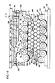
- the rearward portion of the back-up block 64 includes a downwardly-opening concave surface 146 and the rearward portion of the support member 70 includes an upwardly-extending convex portion 148, which is positioned to matingly engage and slide against the concave portion 146.
- the convex portion 148 extends from the upper surface 150 of the support member suffinnenciently to provide a clearance space 151 between the support member 70 and the bottom 152 of the slot 68 to allow for pivotal movement of the support member relative to the back-up block 64, as indicated by broken line A in Fig. 4.
- the concave portion 146 and convex portion 148 both have centers of curvature which coincide with the rotational axis 154 of the rearmost top work roll 156. Accordingly, both the concave portion 146 and convex portion 148 have a radius represented by line B , so that pivotal movement of the support member 70, which causes the convex portion 148 to slide against the concave portion 146, results in the support member 70 pivoting about the rotational axis 154 of the rearmost work roll 156.
- Each upper back-up roller assembly 62 includes an adjusting screw mechanism 164, shown in Figs. 1, 2 and 3.
- Each adjusting screw mechanism 164 includes a separate drive motor 166 which is drivingly connected to a gear box 168, both of which are mounted on the top plate 169.
- Each gear box 168 receives the upper end of a jack screw 170 which extends downwardly through the upper frame 16 and mounting plate 60.
- each jack screw 170 engages the upper one of a pair of spherical bearings 172, the lower one of which engages a removable pin 174 fitted within a bore 176 formed in the back-up block 64.
- the lower end of each pin is connected to a second set of spherical bearings 178 which abut the upper surface 150 of the support member 70.
- the spherical bearings 172, 178 provide a positive connection between the jack screw 170 and pin 174, and between the pin 174 and support member 70, throughout the range of pivotal movement of the support member, and to compensate for any misalignment between components.
- the pins 174 facilitate the removal of replacement of the entire assembly attached to mounting plate 60 from the frame 16.
- each adjusting screw mechanism 164 may be independently actuated to raise or lower its associated jack screw 170, to pos ition its back-up roller assembly 62.
- a downward displacement of a jack screw 170 causes its associated support member 70 to pivot in a clockwise direction about axis 154, so that the penetration of the upper work rolls 78 (with the exception of the rearmost work roll 156) is increased.
- An upward displacement of a jack screw 170 allows the resilient members 132 to pivot the support member 70 in a counterclockwise direction relative to back-up block 64 so that the penetration of the work rolls 78 is decreased.
- the defect is that the length of the center of the strip is greater than at the edges, resulting in center buckle.
- the support members 70 of the roller assemblies 62 immediately above the edges of the strip are deflected downwardly by their associated adjusting screw mechanisms 164 (Fig. 2), thereby increasing the penetration of the work rolls 78 in the region of the edge of the strip.
- the operation of the leveling apparatus is as follows.
- a strip of metal is fed into the leveling apparatus from right to left, as shown in Figs. 1 and 4, and extends between the upper and lower sets of work rolls 78, 58.
- the upper frame 16 will be raised or lowered by the corner jack screws 20 to adjust the final penetration of the upper work rolls 78 into the lower work rolls 58.
- a dividing line 182 extends between the upper and lower work rolls. Penetration is increased when the upper work rolls 78 are urged downwardly.
- the individual adjusting screw mechanisms 164 are continuously actuated to pivot their respective support members 70 to vary the penetration of those portions of the upper work rolls 78 immediately below them, in order to correct for waves or buckles in the sheet 180 in those areas immediately below the specific upper back-up roller assemblies 62.
- each adjusting screw 164 may be actuated by an operator, or by utilizing well-known sensor mechanisms, such as those disclosed in Buta U.S. Patent No. 4,454,738, the disclosure of which is incorporated herein by reference.
- rollers 72 of the upper back-up roller assemblies 62, and the rollers 54 of the lower back-up roller assemblies 50 are not continuous rolls like intermediate back-up rolls 76, 56, there is a tendency for the strip 180 to receive longitudinal markings corresponding to the outer edges of the rollers.
- two components of the leveling apparatus act to reduce the formation of such markings.
- the preferred embodiment of the invention includes intermediate back-up rolls 76, 56 which are interposed between the rollers 72, 54 and the work rolls 78, 58, respectively.
- the back-up rolls may be provided with spiral grooves which break up the pattern created by back-up rollers 54 and 72. It has been found that such an arrangement is effective in reducing the formation of longitudinal markings on the strip.
Landscapes
- Engineering & Computer Science (AREA)
- Mechanical Engineering (AREA)
- Straightening Metal Sheet-Like Bodies (AREA)
- Soil Working Implements (AREA)
Priority Applications (3)
| Application Number | Priority Date | Filing Date | Title |
|---|---|---|---|
| US06/726,542 US4635458A (en) | 1985-04-24 | 1985-04-24 | Leveling apparatus |
| EP19860307236 EP0260361B1 (de) | 1986-09-19 | 1986-09-19 | Richtmaschine |
| DE8686307236T DE3684919D1 (de) | 1986-09-19 | 1986-09-19 | Richtmaschine. |
Applications Claiming Priority (1)
| Application Number | Priority Date | Filing Date | Title |
|---|---|---|---|
| EP19860307236 EP0260361B1 (de) | 1986-09-19 | 1986-09-19 | Richtmaschine |
Publications (3)
| Publication Number | Publication Date |
|---|---|
| EP0260361A2 true EP0260361A2 (de) | 1988-03-23 |
| EP0260361A3 EP0260361A3 (en) | 1988-06-08 |
| EP0260361B1 EP0260361B1 (de) | 1992-04-15 |
Family
ID=8196149
Family Applications (1)
| Application Number | Title | Priority Date | Filing Date |
|---|---|---|---|
| EP19860307236 Expired EP0260361B1 (de) | 1985-04-24 | 1986-09-19 | Richtmaschine |
Country Status (2)
| Country | Link |
|---|---|
| EP (1) | EP0260361B1 (de) |
| DE (1) | DE3684919D1 (de) |
Cited By (4)
| Publication number | Priority date | Publication date | Assignee | Title |
|---|---|---|---|---|
| EP0350671A3 (en) * | 1988-07-13 | 1990-10-10 | Dornier Gmbh | Apparatus for bending or straightening work pieces by plastic deformation |
| EP0615797A1 (de) * | 1993-03-19 | 1994-09-21 | Sms Schloemann-Siemag Aktiengesellschaft | Richtmaschine, insbesondere zum Richten von Blechen und Bändern |
| GB2411140A (en) * | 2004-02-17 | 2005-08-24 | Bronx Mfg Company | Levelling Machine and Method |
| CN110227739A (zh) * | 2019-07-25 | 2019-09-13 | 济南艺高数控机械有限公司 | 快速换辊校平机 |
Family Cites Families (7)
| Publication number | Priority date | Publication date | Assignee | Title |
|---|---|---|---|---|
| US2827945A (en) * | 1949-07-28 | 1958-03-25 | Frederick K Maust | Roller leveler with upper-roller adjusting means |
| US2963071A (en) * | 1957-03-15 | 1960-12-06 | Lake Erie Machinery Corp | Leveler for sheet metal strips |
| DE1988614U (de) * | 1963-11-29 | 1968-07-04 | Siemag Siegener Masch Bau | Blechrichtmaschine mit in einem gestell gegeneinander anstellbaren richtwalzen. |
| US3301031A (en) * | 1964-06-23 | 1967-01-31 | Voss Engineering Company | Roller leveler |
| US3420082A (en) * | 1966-06-02 | 1969-01-07 | Wilson Eng Co Inc Lee | Leveler |
| DE1752211C3 (de) * | 1968-04-20 | 1975-10-09 | Wilhelmsburger Maschinenfabrik, Hinrichs & Sohn, 2054 Geesthacht | Feinblechrichtmaschine |
| US4454738A (en) * | 1981-06-29 | 1984-06-19 | The Paxson Machine Company | Roller leveler and method of operating same |
-
1986
- 1986-09-19 EP EP19860307236 patent/EP0260361B1/de not_active Expired
- 1986-09-19 DE DE8686307236T patent/DE3684919D1/de not_active Expired - Lifetime
Cited By (6)
| Publication number | Priority date | Publication date | Assignee | Title |
|---|---|---|---|---|
| EP0350671A3 (en) * | 1988-07-13 | 1990-10-10 | Dornier Gmbh | Apparatus for bending or straightening work pieces by plastic deformation |
| EP0615797A1 (de) * | 1993-03-19 | 1994-09-21 | Sms Schloemann-Siemag Aktiengesellschaft | Richtmaschine, insbesondere zum Richten von Blechen und Bändern |
| GB2411140A (en) * | 2004-02-17 | 2005-08-24 | Bronx Mfg Company | Levelling Machine and Method |
| WO2005080016A3 (en) * | 2004-02-17 | 2005-12-08 | Bronx Mfg Company Uk Ltd | Levelling machine and method |
| GB2411140B (en) * | 2004-02-17 | 2007-05-16 | Bronx Mfg Company | Levelling machine and method |
| CN110227739A (zh) * | 2019-07-25 | 2019-09-13 | 济南艺高数控机械有限公司 | 快速换辊校平机 |
Also Published As
| Publication number | Publication date |
|---|---|
| DE3684919D1 (de) | 1992-05-21 |
| EP0260361B1 (de) | 1992-04-15 |
| EP0260361A3 (en) | 1988-06-08 |
Similar Documents
| Publication | Publication Date | Title |
|---|---|---|
| US4635458A (en) | Leveling apparatus | |
| US5009098A (en) | Press and curve-forming means therefor | |
| AU720605B2 (en) | Roll forming apparatus and method | |
| DE3212070C2 (de) | Walzgerüst mit einer Vorrichtung zur Einhaltung der Ebenheit des gewalzten Guts | |
| US3301031A (en) | Roller leveler | |
| US4406141A (en) | Straightening apparatus for steel pipes and the like | |
| US4289013A (en) | Crown control for rolling mill | |
| RU2118920C1 (ru) | Правильная машина, в частности для правки листов и полос | |
| CN87104310A (zh) | 生产轧制件、特别是轧制带材的轧辊机 | |
| US6282932B1 (en) | Axial and transverse roller die adjustment apparatus and method | |
| US6644086B1 (en) | Retro-fit roll forming mill with jack screw | |
| WO1980002810A1 (en) | Forming leveller | |
| EP0260361B1 (de) | Richtmaschine | |
| JP3305840B2 (ja) | 多数本のロールの支持構造物 | |
| US5195347A (en) | Guide device for shape rolling | |
| US3420082A (en) | Leveler | |
| US5191780A (en) | Roller-type straightening apparatus for h-beams | |
| DE3331339C2 (de) | ||
| US5908989A (en) | Method and apparatuses for measuring and correcting the stress profile of saw blades | |
| US6220071B1 (en) | Method and apparatus for controlling strip edge relief in a cluster rolling mill | |
| EP0247886A2 (de) | Profilierwalzwerk | |
| CA2240249C (en) | Roll forming apparatus and method with single adjuster | |
| CN1104134A (zh) | 薄板两端咬口一次成型机 | |
| JPS63104723A (ja) | レベラ− | |
| CN121266992B (zh) | 一种w型钢的矫正方法 |
Legal Events
| Date | Code | Title | Description |
|---|---|---|---|
| PUAI | Public reference made under article 153(3) epc to a published international application that has entered the european phase |
Free format text: ORIGINAL CODE: 0009012 |
|
| AK | Designated contracting states |
Kind code of ref document: A2 Designated state(s): DE FR GB IT SE |
|
| PUAL | Search report despatched |
Free format text: ORIGINAL CODE: 0009013 |
|
| AK | Designated contracting states |
Kind code of ref document: A3 Designated state(s): DE FR GB IT SE |
|
| 17P | Request for examination filed |
Effective date: 19881207 |
|
| 17Q | First examination report despatched |
Effective date: 19900702 |
|
| GRAA | (expected) grant |
Free format text: ORIGINAL CODE: 0009210 |
|
| ITF | It: translation for a ep patent filed | ||
| AK | Designated contracting states |
Kind code of ref document: B1 Designated state(s): DE FR GB IT SE |
|
| REF | Corresponds to: |
Ref document number: 3684919 Country of ref document: DE Date of ref document: 19920521 |
|
| ET | Fr: translation filed | ||
| PLBE | No opposition filed within time limit |
Free format text: ORIGINAL CODE: 0009261 |
|
| STAA | Information on the status of an ep patent application or granted ep patent |
Free format text: STATUS: NO OPPOSITION FILED WITHIN TIME LIMIT |
|
| 26N | No opposition filed | ||
| EAL | Se: european patent in force in sweden |
Ref document number: 86307236.9 |
|
| REG | Reference to a national code |
Ref country code: GB Ref legal event code: IF02 |
|
| REG | Reference to a national code |
Ref country code: FR Ref legal event code: CA Ref country code: FR Ref legal event code: CD Ref country code: FR Ref legal event code: TP |
|
| PGFP | Annual fee paid to national office [announced via postgrant information from national office to epo] |
Ref country code: IT Payment date: 20050330 Year of fee payment: 20 |
|
| PGFP | Annual fee paid to national office [announced via postgrant information from national office to epo] |
Ref country code: GB Payment date: 20050914 Year of fee payment: 20 |
|
| PGFP | Annual fee paid to national office [announced via postgrant information from national office to epo] |
Ref country code: FR Payment date: 20050919 Year of fee payment: 20 |
|
| PGFP | Annual fee paid to national office [announced via postgrant information from national office to epo] |
Ref country code: SE Payment date: 20050921 Year of fee payment: 20 |
|
| PGFP | Annual fee paid to national office [announced via postgrant information from national office to epo] |
Ref country code: DE Payment date: 20051031 Year of fee payment: 20 |
|
| PG25 | Lapsed in a contracting state [announced via postgrant information from national office to epo] |
Ref country code: GB Free format text: LAPSE BECAUSE OF EXPIRATION OF PROTECTION Effective date: 20060918 |
|
| REG | Reference to a national code |
Ref country code: GB Ref legal event code: PE20 |
|
| EUG | Se: european patent has lapsed |