EP0260362A1 - Perfectionnement aux grues - Google Patents
Perfectionnement aux grues Download PDFInfo
- Publication number
- EP0260362A1 EP0260362A1 EP86307252A EP86307252A EP0260362A1 EP 0260362 A1 EP0260362 A1 EP 0260362A1 EP 86307252 A EP86307252 A EP 86307252A EP 86307252 A EP86307252 A EP 86307252A EP 0260362 A1 EP0260362 A1 EP 0260362A1
- Authority
- EP
- European Patent Office
- Prior art keywords
- crane
- truck
- frame
- tracks
- portable
- Prior art date
- Legal status (The legal status is an assumption and is not a legal conclusion. Google has not performed a legal analysis and makes no representation as to the accuracy of the status listed.)
- Withdrawn
Links
- 230000033001 locomotion Effects 0.000 claims abstract description 13
- 238000000926 separation method Methods 0.000 claims description 25
- 239000000446 fuel Substances 0.000 claims description 3
- 238000003780 insertion Methods 0.000 claims description 2
- 230000037431 insertion Effects 0.000 claims description 2
- 230000001419 dependent effect Effects 0.000 claims 1
- 238000000034 method Methods 0.000 description 21
- 230000000694 effects Effects 0.000 description 11
- 238000010276 construction Methods 0.000 description 10
- 238000006243 chemical reaction Methods 0.000 description 8
- 230000008569 process Effects 0.000 description 6
- 230000006835 compression Effects 0.000 description 4
- 238000007906 compression Methods 0.000 description 4
- 239000003381 stabilizer Substances 0.000 description 4
- 230000008901 benefit Effects 0.000 description 2
- 238000009434 installation Methods 0.000 description 2
- 230000004048 modification Effects 0.000 description 2
- 238000012986 modification Methods 0.000 description 2
- 230000009471 action Effects 0.000 description 1
- 230000004913 activation Effects 0.000 description 1
- 238000010297 mechanical methods and process Methods 0.000 description 1
Images




Classifications
-
- B—PERFORMING OPERATIONS; TRANSPORTING
- B66—HOISTING; LIFTING; HAULING
- B66C—CRANES; LOAD-ENGAGING ELEMENTS OR DEVICES FOR CRANES, CAPSTANS, WINCHES, OR TACKLES
- B66C23/00—Cranes comprising essentially a beam, boom, or triangular structure acting as a cantilever and mounted for translatory of swinging movements in vertical or horizontal planes or a combination of such movements, e.g. jib-cranes, derricks, tower cranes
- B66C23/62—Constructional features or details
- B66C23/72—Counterweights or supports for balancing lifting couples
- B66C23/78—Supports, e.g. outriggers, for mobile cranes
-
- B—PERFORMING OPERATIONS; TRANSPORTING
- B66—HOISTING; LIFTING; HAULING
- B66C—CRANES; LOAD-ENGAGING ELEMENTS OR DEVICES FOR CRANES, CAPSTANS, WINCHES, OR TACKLES
- B66C23/00—Cranes comprising essentially a beam, boom, or triangular structure acting as a cantilever and mounted for translatory of swinging movements in vertical or horizontal planes or a combination of such movements, e.g. jib-cranes, derricks, tower cranes
- B66C23/62—Constructional features or details
Definitions
- This invention relates to cranes.
- a typical state of the art truck crane is constructed with the crane mounted on the rear portion of the frame, the front portion of the frame including the truck cab and the engine and drive train of the entire vehicle.
- the frame is provided with a series of four outrigger beams such that when the vehicle arrives at the use location, the outrigger beams are extended and the leveling jacks, which are mounted on the end of each outrigger beam in a vertical position, are also extended to engage the ground and raise the entire crane clear of the ground thus effectively supporting the crane on all four outrigger beams and all four leveling jacks. Only in this configuration can the truck crane perform at its rated capacity.
- the crawler crane is then removed from the trailer, and is then available for work at the job site.
- the contracting firm engaged in the construction on the job site is required to have two crane vehicles at the same location in order to accomplish the various lifting and travel functions required by a particular construction project. It will again be appreciated that this is a very costly burden on the contractor since he will have double the labour charges as well as double the equipment charges in order to have the advantage of two different typ es of cranes at the same job site.
- the current state of the art cranes in use have at least two drawbacks with respect to on site usage, those being the limitation in terms of the circumferential path of travel of the crane when employing truck crane of the type with outrigger jacks as well as the immobility of the truck crane once securely positioned on the job site.
- Patent Specification US-A-3 929 204 makes an attempt at solving this problem by providing a crane which is mounted on a wheeled trailer, and which the patentee indicates may be converted to a crawler crane on the job site. It will be observed from a view of Figure 7 of the drawings of the US-A-3 929 204 patent, that the patentee contemplates the mounting of portable tracks onto the trailer frame by unbolting and removing the outrigger jacks, and installing in the same position the portable crane tracks.
- the controls which operate the outrigger jacks are usually positioned on the frame adjacent to the outrigger beams, rather than in the cab and as such, the controls are removed from the cab area. Furthermore, those controls are supplied with only an 18 gallon per minute pump which is insufficient to power the tracks for movement. Therefore, even if one produces a crawler crane as suggested (by Newell), there is no teaching of how such a crane would be powered. Hence, it is believed that the Patentee has not truly resolved the difficulties and problems encountered in terms of converting a truck crane to a crawler crane.
- the present invention is therefore intended to provide a mechanical system for converting presently existing wheeled crane vehicles to a crawler crane, and to incorporate within such a system the ability to connect a power source for the tracks to the main crane cab such that the operator has full control over the functions of the crawler crane.
- each of the portable crane tracks is provided with corresponding mounting fixtures such that the mounting means on the frame and the mounting fixtures on the portable tracks may be placed in registry with each other thereby to mount the tracks onto the frame thereby to convert the truck crane to a crawler crane.
- a further object of the present invention is to provide a pair of portable crane tracks of the type described, each of which is formed by a forward and rear support plate for supporting the tracks thereon and having a respective inner meeting ends, the forward and rear support plates being interconnected by a centrally positioned pivot plate whereby the forward and rear support plates are movable with respect to each other throughout an arc of approximately 180 degrees whereby said portable crane tracks are foldable for ease of transportation and having over all length and width dimensions which comply with state highway regulations, and while on the other hand, may be easily manipulated to unfold the same and install the same onto the rear frame section incident to the crane conversion process.
- Yet another object of the present invention is to provide a mechanical system of the type described above for converting a truck crane into a crawler crane, wherein the presently existing frame and drive train of the truck crane may be severed, and adapted to be disengageably engageable in order to create a separable forward section, and a rear frame section, which may also include power operated separation means for separating the respective frame members, and employing a splined drive train and a splined housing for permitting the separation and reengagement of the drive train incident to the conversion process.
- the present invention provides a method and system, and the mechanical elements involved, for converting a presently available truck crane, whether of the lattice boom type, or hydraulic boom type, into a crawler crane.
- the present invention contemplates that the conversion process may be effected on the job site, thereby eliminating the need to procure and have on site multiple crane systems in order to complete a given construction project.
- the present invention contemplates the driving of a truck crane to the job site, after which, the frame and drive train thereof may be separated, and a pair of portable tracks mounted onto the rear frame section of the vehicle.
- the tracks once mounted, will maintain the frame section in an elevated position such that the wheels contained thereon are kept out of engagement with the underlying ground surface, in order to have the crawler crane operate properly. Furthermore, the present invention shows that at least one of the portable tracks contains an independent power source which may be connected to its own separate control system by means of hydraulic lines or the like, such that the crane operator in the crane cab will have full control over the motive power to be applied to the tracks as well as the directional control thereover.
- the cantilevered effect which is found in typical truck cranes can be eliminated, such that the crane once converted to a crawler crane on the job site, will have the full lifting and work arc of 360 degrees and will not be hampered by the cantilever effect presently existing with truck cranes.
- the present invention is intended to provide the presently available truck cranes with a method of utilising a truck crane to its fullest capabilities by permitting the easy conversion thereof to a crawler crane on the job site. It is once again, important to note that truck cranes have several drawbacks when being used on a job site location which therefore necessitate that crawler cranes be transported to the job sites such that multiple cranes are generally located on a single job site. The disadvantages noted with respect to truck cranes are important with respect to an appreciation of the present invention, since the present invention substantially eliminates these problems.
- truck cranes typically are driven to a job site, and once the proper location for the work effort is located, the truck crane outrigger beams are extended and the leveling jacks, which are fixedly secured to the end of each outrigger beam in a vertical position, are also extended to engage the ground and lift the entire truck crane from ground engagement. Since each leveling jack is independently operated, one can effectively level the crane on uneven ground. It is only in this position that the truck crane's rated capacity (ability to lift a given mass (number of pounds) at a given distance from the crane) can be achieved.
- the crane operator only has approximately three quadrants, or an arc of 270 degrees, to work the crane on the job site location, those three quadrants being the respective opposed sides of the crane, and the portion to the rear of the truck cab which is rearward of the forward outriggers.
- the present invention permits the truck crane to be converted to a crawler crane on site, and hence, gives the crane operator mobility with respect to moving lifted loads from locale to locale.
- the crane operator is in a position to control the forward and rear motion of each of the tracks independently of one another, as well as to control the speed thereof.
- truck cranes 10 of the type illustrated are presently commercially available, and are well known in the art.
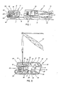
- the truck crane tows a trailer 12 which contains two foldable portable tracks 14 shown positioned thereon. In this manner, the portable tracks 14 may be towed to the job site location by the truck crane 10.
- the truck crane typically, is formed by a forward cab portion 16, and a frame 18, which carries the crane 20 thereon.
- the frame 18 is provided with a plurality of wheels 22 which accomplishes the transporting function.
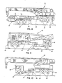
- FIG. 8 there is shwon a hydraulic boom truck crane 30.
- the boom truck crane 30 includes a forward cab portion 32, and a rear frame portion 34 respectively.
- the drive train is operable to drive one pair of front wheels 33, as well as one of the pair of rear wheels 35.
- the rear frame portion 34 is shown in include a series of four outrigger jacks 38, two of which are located on each of the opposed sides of the frame portion 30 as is typically known in the art.
- the front cab portion 32 is shown to be separated from the rear frame portion 34, with the rear frame portion 34 shown in its jacked and elevated position by having activated the outrigger jacks 38 in a manner known in the art, such that the rear wheels 35 are now elevated with respect to the underlying ground.
- the front cab portion may simply be stored in a safe location.
- Figure 9 is intended to illustrate the adaptability of the present invention to a lattice truck crane 40 of the type formed by a forward cab portion 42, a rear frame portion 44, and having a pair of front wheels 43, and rear wheels 45.
- the frame portion 44 is shown to include a series of four outrigger jacks 48 as is well known in the art.
- the rear frame portion 44 is shown to be separaed from the front cab portion 42, with the rear frame portion 44 being elevated by means of the activation of the outrigger jacks 48.
- the front cab portion 42 does not contain a drive train capable of driving the front cab portion independently of the entire assembly, and hence, the present invention contemplates employing a stabiliser foot 49 which would permit the cab portion 42 to simply remain in position, but separated from the rear frame portion 44.
- the relevant feature is the ability to separate the cab portion 42 from the rear frame portion 44 such that when the portable tracks are installed on the rear section 44, once again, the operator of the crane will not have the problem of a cantilevered effect over the front cab portion 42 in terms of any lifting functions with respect to the operation of the crane 40 and will have the ability to walk up to a load, lift the same, and travel to a site location.
- the rear frame portion 44 is provided with a series of four outrigger beams 46 which are laterally movable within beam housing 47.
- the outrigger jacks 48 are each fixedly secured to a corresponding outrigger beam 46 and each is movable in a vertical direction.
- the outrigger beams 46 are laterally moved outwardly to their fullest extent and the outrigger jacks 48 lowered to ground level until the crane is lifted out of ground engagement.
- the jacks operate within standards 100 which also act as jack housings. It will therefore be appreciated that the outrigger jacks 48 remain on the frame 44 to permit the engagement of the portable tracks 14 onto the frame 44. This procedure is applicable with respect to each of the crane configurations as illustrated in the drawings.
- a hydraulic boom crane 50 which is formed to include a front cab portion 52, a rear frame portion 54, a pair of front wheels 53, and a series of rear wheels 55.
- the hydraulic boom crane 50 is shown to include a front cab portion 52 which has no independent drive wheels and hence, a stabiliser foot 57 may similarly be adapted to the front cab portion 52 in order to balance and maintain the front cab portion in position once the frame members have been separated.
- the crane operator after installing the portable tracks on the rear frame portion 54, will eliminate the problem of lifting over the forward cab portion 52, and now has the ability to engage in lifting loads throughout a full 360 degree arc around the crane 50, and travel with such loads in the lifted posture.
- FIG. 11 and 12 one embodiment is illustrated for effecting the separation of the front cab portion 52 from the rear frame portion 54.
- the rear frame portion 54 may be designed to include a tongue 58
- the front cab portion 52 is shown to include a bifurcated section 59 which is sized in a manner to accommodate the tongue portion 58 therein.
- a pair of connection bolts 61 may be inserted through apertures appropriately provided such that when the tongue 58 and bifurcated section 59 are re-engaged, the connection bolts 61 are inserted therethrough to firmly lock the front cab portion 52 to the rear frame portion 54.
- connection bolts 61 can easily be removed, and then the outrigger jacks 56 manipulated to raise the rear frame poriton 54 relative to the front cab portion 52.
- the elevation of the jacks 56 will cause the tongue 58 to be removed from the bifurcated section 59 in the manner illustrated in Figure 11, after which the front cab portion 52 may simply be removed leaving the rear frame portion 54 with the crane 50 in an elevated and free standing position.
- the hydraulic cylinder 62 includes a cylinder housing 63 which is connected to the front cab portion 52 by means of a connection eye 64 and includes a cylinder rod 66 which moves within the cylinder housing 63 in its rear portion, and is fixedly secured to a cylinder shroud 68 at its forward end.
- the cylinder shroud 68 includes an internal connection eye 69 which is, in turn, disengageably secured to the rear frame portion 54 by means of a bolt, or other connection means, via aperture 71.
- the hydraulic cylinder 62 is shown to be in its fully extended position which has the effect of supporting the front cab portion 52 relative to the rear frame portion 54.
- the cylinder rod 66 and the cylinder shroud 68 may then be retracted back into the front cab portion 52 as illustrated in Figure 15 of the drawings.
- the frame members are split along the phantom line 72 such that when the cylinder rod 66 and shroud 68 are fully retracted as shown in Figure 16, the outrigger jack 56 may be activated to raise the rear frame portion 54 relative to the front cab portion 52.
- the respective frame members will then be separated along the frame split line 72 as illustrated.
- the front cab portion 52 and rear frame portion 54 may be hydraulically separated in the manner illustrated to accomplish the separation.
- the crane operator may then operate the crane in the manner heretofore described to install the portable tracks as exemplified in Figures 2 through 5 of the drawings.
- the crane 50 is then in an independent posture with the front cab portion 52 eliminated therefrom, such that the crane is now converted to a crawler crane, with full mobility, and a 360 degree arc of lifting function.
- the method or means for separating frame may be manual, hydraulic, or may assume any other format which would mechanically function to split the frame, separate the same, and effect a lifting function with respect to the rear frame portion. It is contemplated that Figures 11 and 12 illustrate a manual method for effecting the separation, while Figures 14 through 16 illustrate a hydraulic means for accomplishing the same function.
- a drive train 75 constructed in the manner as illustrated in Figure 13 will operate to effect the necessary separation.
- the drive train is shown to include a drive shaft 76 which is formed to have an interior chamber 77 with a splined housing 85 incorporated therein.
- the rear portion of the interior chamber 77 is accommodated with a spline shaft 78 of sufficient length for retraction to effect separation and re-engagement.
- Disengagement is accomplished by hydraulic jacks 81 and 82 when their associated slotted cylinder heads 81a and 81b, which hold the shaft 78 within the collar 79, are retracted.
- jacks 81 and 82 are activated to retract cylinders 81a and 81b effectively retracting the splined shaft 78 against the spring 83.
- the jacks 81 and 82 are relaxed permitting the biasing action of spring 83 to force the splined shaft 78 into engagement with the splined housing 85.
- the method or means for separating the shaft may be manual, hydraulic (as shown), or assume any other format which would mechanically function to split the shaft, separate the same, and permit re-engagement. It is contemplated that the manual method would include a movable sleeve which would overlie the two shaft sections to hold the forward and rear sections of the shaft in position, and slideably move to permit separation.
- the rear frame portion 54 is shown to be provided with a splined housing 85 which is sized in a manner to accommodate the splined shaft 78 when the respective front cab portion 52 and rear frame portion 54 are joined together. It will be appreciated that when the respective frame portions 52 and 54 are joined together, the compression spring 83 will operate to biasingly maintain the splined shaft 78 into a journalled relationship with respect to the splined housing 85. When so joined, it will be appreciated that the motive power generated by the drive train 75 will be translated to the rear drive axle 87 in a manner which is known in the art, such that motive power is then provided to the rear wheels 55.
- any other system aboard the subject truck crane may be similarly designed with quick disconnects, hence, such items as brake lines, fuel lines and the like may be designed with quick disconnects such tha t any of the hydraulic or fuel lines existing in the undercarriage of the vehicle may similarly be separated at the time of separation of the axle and the drive train.
- each of the pair of foldable tracks 14 was formed by a forward support plate 15 and a rear support plate 17 which function to support the tracks 19 thereon.
- the forward support plate 15 and the rear support plate 17 are foldable with respect to each other, by means of a pivot plate 21 which is pivotally secured to each of the forward and rear support plates 15 and 17 respectively at pivot points 23 and 24.
- pivot plate 21 is provided with a pair of securement apertures 26 and 27 respectively.
- Each of the portable foldable tracks 14 is shown to further include a pair of raised apertured gusset plates 90 which are fixedly secured to the forward and rear support plates 15 and 17 respectively.
- the rear frame portion 44 of the lattice boom truck crane 40 is provided with two pairs of outrigger beams 46 which are apertured adjacent the outer end 94 thereof, and include an upstanding standard 100 formed thereon which are fixedly secured to portions of the frame as more particularly shown in Figures 5 and 6 of the drawings.
- each gusset plate is actually formed by a pair of spaced plates 91 and 92, the plates 91 and 92 being spaced a sufficient distance to accommodate the apertured standard 100 therebetween.
- a separate apertured block 103 is provided, which is sized to fit between the spaced plates 91 and 92 respectively, of each gusset plate 90.
- the aperture 101 formed in the block 103 comes into registry with a corresponding aperture 93 formed in the plates 91 and 92.
- the gusset plates include a pair of apertures 93 and 94 which, during the mounting procedure, come into registry with corresponding apertures 101 and 102 ( Figure 4) formed in the apertured standards 100 and apertured blocks 103.
- each of the tracks 14 is provided with lift pins 96 in order to permit the lattice boom crane 40 to perform the lifting function.
- the lift pins 96 are located on both the forward and rear support plates 15 and 17 respectively such that once the track has been unfolded as illustrated in phantom in Figure 3, appropriate cables from the lattice boom crane 25 may be hooked onto the lift pins in both the forward and rear positions in order to lift the entire track incident to the mounting procedure, as illustrated in Figure 4.
- each of the foldable tracks 14 may be provided with an independent power source 105 which is fixedly secured to one of the support plates 15 or 17 respectively.
- the power source 105 is provided with motive power connection means (not shown) wh ich permits the attachment thereto of flexible motive lines such as hydraulic lines 107 ( Figure 6) which interconnect the power source 105 to the crane 20. It will further be appreicated that the power source 105 is mechanically connected to the track gears 109 in a manner which is well known in the art.
- the power source 105 which is mounted to the portable track 14, is adapted to receive the hydraulic lines emanating from the crane 20, thereby to interconnect the power source with the controls located in the cab of the crane 20, and to similarly be interconnected with the track gears 109 such that the operator of the crane 20 will have full and complete control over the crawler crane once the tracks 14 are installed onto the frame as indicated hereinabove.
- the attachment fixtures for attaching the tracks 14 to the frame 44 must be positioned as such that the overall carriage and frame 44 of the vehicle be in an elevated position in order to alleviate any difficulties which may exist with respect to the rear wheels being in any type of touching contact with the underlying ground once the tracks 14 are installed onto the vehicle.
- the jacks 38, 48 or 56 are retracted thus effectively transferring the weight of the crane to the tracks 14 thereby establishing mobility.
- FIG. 17 the manner in which the tracks 14 may be controlled by the crane cab 20 is illustrated.
- the undercarriage 110 of the crane is illustrated.
- Figure 18 is intended to illustrate the interior of the crane cab 20 showing a master control box 112 which incorporates a split handle 113 and 114 respectively.
- the master control box 112 includes electrical contacts such that the positioning of the split handles 113 and 114 will electrically actuate the forward and rearward motion of the tracks independently of one another.
- electrical conduits 116 extend from the master control box 112 to spring loaded contact shoes 118.
- the spring loaded contact shoes are shown to include a base plate 119 carrying a coiled spring 121 there atop.
- a compression arm 123 is pivotally mounted to the base plate 119 and extends over the top of the coiled spring 121.
- a locking arm 125 is similarly pivotally mounted to the base plate 119 which is designed to move forward and lockingly engage the compression arm 123.
- a contact shoe 127 is mounted to the base plate 119 and extended downwardly thereform for engagement in an appropriate U-shaped track 130. It will be apparent that each of the contact shoes 127 may be disengaged from the corresponding U-shaped track 130 by manually effecting the compression of the coiled spring 121 such that the base plate 119 moves upwardly thereby carrying the contact shoe 127 upwardly.
- each of the spring loaded contact shoes 118 may be disengaged from an appropriate U-shaped track 130 and lockingly held in position by causing the locking arm 125 to lockingly engage a pin 128 thereby maintaining the contact shoe 127 out of electrical contact with the U-shaped track 130 to prevent the shoes 127 from wea ring out when the track attachment is not in use.
- the spring loaded contact shoes 118 are mounted to the under portion of the crane cap 20, and designed to run in a number of U-shaped tracks 130 as is illustrated in Figures 17 and 18 of the drawings.
- Each of the electrical conduits 116 emanating from the control box 112 are therefore designed to operate the portable tracks.
- Movement of handle 113 will move the right track in reverse thus effectively enabling the operator to turn the crane within its own radius.
- the movement of both handles 113 and 114 forwrdly will move both the right and left tracks forward, while movement of the handles 113 and 114 rearwardly will move both tracks in reverse.
- independent control of each track is established from the cab portion of the crane.
- the controls which control the various crane functions are similarly located in the cab portion of the crane 20, as is well known in the art. But as illustrated, the present invention provides an independent control system located in the cab of the crane 20 for controlling the independent movement of each of the tracks once installed on the frame.
- each of the tracks 14 includes a hydraulic motor 135 which in turn operate the track gears 109 in a manner which is again, known in the art.
- hydraulic line connections via flexible hydraulic lines 107 are established as between the independent power source 105, and the hydraulic motors 135, which in turn will operate the track gears 109, in a manner presently utilised on cranes of this construction.
- an improved convertible truck crane has been provided.
- the improvements pursuant to the present invention permit a presently commercially available truck crane to be converted to a crawler crane by splitting the frame of the vehicle as well as the drive train thereof, utilising mechanical and/or hydraulic/mechanical means for effecting the disengagement of the frame as well as the drive train.
- the drive train as previously indicated, may be splined, and includes a splined housing, such that the drive train may be easily engaged and/or disengaged when put into use.
- the cab portion of the truck crane may be removed, after which the portable foldable tracks may be installed onto the rear frame section of the vehicle.
- the resulting crawler crane which is now created eliminates the "no lift" quadrant presently encountered with truck cranes, that being the quadrant of lifting over the forward portion of the cab of the truck crane, and permits the crawler crane now created, to walk up to a load, lift the same, and walk with the load to any site location.
- the present invention provides a truck crane convertible to a crawler crane configuration, wherein each of the portable tracks may be independently controlled from the crane cab, giving the operator the ability to control the forward and reverse directions of the crane, as well as the speed of each of the tracks independently of one another.
Landscapes
- Engineering & Computer Science (AREA)
- Mechanical Engineering (AREA)
- Jib Cranes (AREA)
Priority Applications (2)
| Application Number | Priority Date | Filing Date | Title |
|---|---|---|---|
| US06/705,904 US4640421A (en) | 1985-02-26 | 1985-02-26 | Truck crane conversion to crawler crane |
| EP86307252A EP0260362A1 (fr) | 1986-09-19 | 1986-09-19 | Perfectionnement aux grues |
Applications Claiming Priority (1)
| Application Number | Priority Date | Filing Date | Title |
|---|---|---|---|
| EP86307252A EP0260362A1 (fr) | 1986-09-19 | 1986-09-19 | Perfectionnement aux grues |
Publications (1)
| Publication Number | Publication Date |
|---|---|
| EP0260362A1 true EP0260362A1 (fr) | 1988-03-23 |
Family
ID=8196150
Family Applications (1)
| Application Number | Title | Priority Date | Filing Date |
|---|---|---|---|
| EP86307252A Withdrawn EP0260362A1 (fr) | 1985-02-26 | 1986-09-19 | Perfectionnement aux grues |
Country Status (1)
| Country | Link |
|---|---|
| EP (1) | EP0260362A1 (fr) |
Cited By (3)
| Publication number | Priority date | Publication date | Assignee | Title |
|---|---|---|---|---|
| WO2008141095A1 (fr) * | 2007-05-09 | 2008-11-20 | Davis Daniel E | Poseur de tuyau et procédé de chargement de poseur de tuyau ou d'excavateur pour transport |
| US20220194756A1 (en) * | 2020-12-18 | 2022-06-23 | Tadano Faun Gmbh | Set-up method for a mobile crane and mobile crane |
| CN117775960A (zh) * | 2024-02-28 | 2024-03-29 | 临沂大学 | 一种烟气脱硫塔安装吊装设备 |
Citations (4)
| Publication number | Priority date | Publication date | Assignee | Title |
|---|---|---|---|---|
| DE2030250A1 (de) * | 1970-06-19 | 1971-12-30 | Rheinstahl Ag, 4300 Essen | Auf Raupenfahrwerken fahrbarer Kran |
| GB1285062A (en) * | 1968-09-19 | 1972-08-09 | Potain Sa | Improvements in or relating to cranes |
| US3929204A (en) * | 1975-01-22 | 1975-12-30 | Lawrence Hugh Newell | Trailer crane with outrigger to crawler conversion |
| DE3013513A1 (de) * | 1979-04-09 | 1980-10-30 | Harnischfeger Corp | Umruestbare maschine mit einem ausleger |
-
1986
- 1986-09-19 EP EP86307252A patent/EP0260362A1/fr not_active Withdrawn
Patent Citations (4)
| Publication number | Priority date | Publication date | Assignee | Title |
|---|---|---|---|---|
| GB1285062A (en) * | 1968-09-19 | 1972-08-09 | Potain Sa | Improvements in or relating to cranes |
| DE2030250A1 (de) * | 1970-06-19 | 1971-12-30 | Rheinstahl Ag, 4300 Essen | Auf Raupenfahrwerken fahrbarer Kran |
| US3929204A (en) * | 1975-01-22 | 1975-12-30 | Lawrence Hugh Newell | Trailer crane with outrigger to crawler conversion |
| DE3013513A1 (de) * | 1979-04-09 | 1980-10-30 | Harnischfeger Corp | Umruestbare maschine mit einem ausleger |
Cited By (5)
| Publication number | Priority date | Publication date | Assignee | Title |
|---|---|---|---|---|
| WO2008141095A1 (fr) * | 2007-05-09 | 2008-11-20 | Davis Daniel E | Poseur de tuyau et procédé de chargement de poseur de tuyau ou d'excavateur pour transport |
| US20220194756A1 (en) * | 2020-12-18 | 2022-06-23 | Tadano Faun Gmbh | Set-up method for a mobile crane and mobile crane |
| US11724921B2 (en) * | 2020-12-18 | 2023-08-15 | Tadano Faun Gmbh | Set-up method for a mobile crane and mobile crane |
| CN117775960A (zh) * | 2024-02-28 | 2024-03-29 | 临沂大学 | 一种烟气脱硫塔安装吊装设备 |
| CN117775960B (zh) * | 2024-02-28 | 2024-05-03 | 临沂大学 | 一种烟气脱硫塔安装吊装设备 |
Similar Documents
| Publication | Publication Date | Title |
|---|---|---|
| US4640421A (en) | Truck crane conversion to crawler crane | |
| US4955777A (en) | Aircraft ground handling tractor | |
| GB2248215A (en) | Aircraft ground-handling dolly | |
| AU2024278324B2 (en) | Tire handler having tire lay flat capability | |
| KR102433584B1 (ko) | 공수 가능한 포크리프트 및 적재 방법 | |
| US3680720A (en) | Track laying equipment and carrier therefor | |
| EP3330212A1 (fr) | Grue mobile | |
| EP0260362A1 (fr) | Perfectionnement aux grues | |
| JP2008156047A (ja) | 自走式リフター装置 | |
| US5054744A (en) | Pulling device for removing ground embedded structures | |
| JPH11222071A (ja) | 多機能作業機 | |
| US6182788B1 (en) | Elevating work platform | |
| JPS63106295A (ja) | クロ−ラクレ−ンへの変換トラツククレ−ン | |
| RU228940U1 (ru) | Крановая установка на двухзвенном гусеничном снегоболотоходе | |
| EP1439113A1 (fr) | Mécanisme de remorquage pour véhicules industriels applicable à une sellette d'attelage d'un véhicule tracteur | |
| KR200229953Y1 (ko) | 구난차량용 견인삼각대 구조 | |
| US20030108413A1 (en) | Load lifting attachment for skid-steer loader | |
| US20020074305A1 (en) | Portable and towable lift mechanism attachable to a front end loader | |
| JP4486558B2 (ja) | 走行不能車用台車 | |
| US20060239807A1 (en) | Transporter for ride-on power trowel | |
| US12187175B1 (en) | Tow truck wheel lift assemblies | |
| RU2274559C1 (ru) | Кран-манипулятор | |
| US20030170107A1 (en) | Self-propelled transport and handling device | |
| JPH0663633U (ja) | チュービング装置移動用台車 | |
| RU1776630C (ru) | Самоходный грузоподъемный кран |
Legal Events
| Date | Code | Title | Description |
|---|---|---|---|
| PUAI | Public reference made under article 153(3) epc to a published international application that has entered the european phase |
Free format text: ORIGINAL CODE: 0009012 |
|
| AK | Designated contracting states |
Kind code of ref document: A1 Designated state(s): AT DE FR GB IT |
|
| STAA | Information on the status of an ep patent application or granted ep patent |
Free format text: STATUS: THE APPLICATION IS DEEMED TO BE WITHDRAWN |
|
| 18D | Application deemed to be withdrawn |
Effective date: 19880926 |