EP0260377A2 - Four de calcination à lit fluidifié - Google Patents
Four de calcination à lit fluidifié Download PDFInfo
- Publication number
- EP0260377A2 EP0260377A2 EP87105708A EP87105708A EP0260377A2 EP 0260377 A2 EP0260377 A2 EP 0260377A2 EP 87105708 A EP87105708 A EP 87105708A EP 87105708 A EP87105708 A EP 87105708A EP 0260377 A2 EP0260377 A2 EP 0260377A2
- Authority
- EP
- European Patent Office
- Prior art keywords
- fluidized bed
- disposed
- feed
- nozzle
- cavity
- Prior art date
- Legal status (The legal status is an assumption and is not a legal conclusion. Google has not performed a legal analysis and makes no representation as to the accuracy of the status listed.)
- Ceased
Links
Images

Classifications
-
- G—PHYSICS
- G21—NUCLEAR PHYSICS; NUCLEAR ENGINEERING
- G21F—PROTECTION AGAINST X-RADIATION, GAMMA RADIATION, CORPUSCULAR RADIATION OR PARTICLE BOMBARDMENT; TREATING RADIOACTIVELY CONTAMINATED MATERIAL; DECONTAMINATION ARRANGEMENTS THEREFOR
- G21F9/00—Treating radioactively contaminated material; Decontamination arrangements therefor
- G21F9/04—Treating liquids
- G21F9/06—Processing
- G21F9/14—Processing by incineration; by calcination, e.g. desiccation
-
- B—PERFORMING OPERATIONS; TRANSPORTING
- B01—PHYSICAL OR CHEMICAL PROCESSES OR APPARATUS IN GENERAL
- B01J—CHEMICAL OR PHYSICAL PROCESSES, e.g. CATALYSIS OR COLLOID CHEMISTRY; THEIR RELEVANT APPARATUS
- B01J8/00—Chemical or physical processes in general, conducted in the presence of fluids and solid particles; Apparatus for such processes
- B01J8/18—Chemical or physical processes in general, conducted in the presence of fluids and solid particles; Apparatus for such processes with fluidised particles
- B01J8/1818—Feeding of the fluidising gas
- B01J8/1827—Feeding of the fluidising gas the fluidising gas being a reactant
-
- B—PERFORMING OPERATIONS; TRANSPORTING
- B01—PHYSICAL OR CHEMICAL PROCESSES OR APPARATUS IN GENERAL
- B01J—CHEMICAL OR PHYSICAL PROCESSES, e.g. CATALYSIS OR COLLOID CHEMISTRY; THEIR RELEVANT APPARATUS
- B01J8/00—Chemical or physical processes in general, conducted in the presence of fluids and solid particles; Apparatus for such processes
- B01J8/18—Chemical or physical processes in general, conducted in the presence of fluids and solid particles; Apparatus for such processes with fluidised particles
- B01J8/1836—Heating and cooling the reactor
-
- B—PERFORMING OPERATIONS; TRANSPORTING
- B01—PHYSICAL OR CHEMICAL PROCESSES OR APPARATUS IN GENERAL
- B01J—CHEMICAL OR PHYSICAL PROCESSES, e.g. CATALYSIS OR COLLOID CHEMISTRY; THEIR RELEVANT APPARATUS
- B01J8/00—Chemical or physical processes in general, conducted in the presence of fluids and solid particles; Apparatus for such processes
- B01J8/18—Chemical or physical processes in general, conducted in the presence of fluids and solid particles; Apparatus for such processes with fluidised particles
- B01J8/24—Chemical or physical processes in general, conducted in the presence of fluids and solid particles; Apparatus for such processes with fluidised particles according to "fluidised-bed" technique
- B01J8/44—Fluidisation grids
-
- B—PERFORMING OPERATIONS; TRANSPORTING
- B01—PHYSICAL OR CHEMICAL PROCESSES OR APPARATUS IN GENERAL
- B01J—CHEMICAL OR PHYSICAL PROCESSES, e.g. CATALYSIS OR COLLOID CHEMISTRY; THEIR RELEVANT APPARATUS
- B01J2208/00—Processes carried out in the presence of solid particles; Reactors therefor
- B01J2208/00008—Controlling the process
- B01J2208/00017—Controlling the temperature
- B01J2208/00389—Controlling the temperature using electric heating or cooling elements
- B01J2208/00407—Controlling the temperature using electric heating or cooling elements outside the reactor bed
-
- B—PERFORMING OPERATIONS; TRANSPORTING
- B01—PHYSICAL OR CHEMICAL PROCESSES OR APPARATUS IN GENERAL
- B01J—CHEMICAL OR PHYSICAL PROCESSES, e.g. CATALYSIS OR COLLOID CHEMISTRY; THEIR RELEVANT APPARATUS
- B01J2208/00—Processes carried out in the presence of solid particles; Reactors therefor
- B01J2208/00008—Controlling the process
- B01J2208/00017—Controlling the temperature
- B01J2208/00389—Controlling the temperature using electric heating or cooling elements
- B01J2208/00415—Controlling the temperature using electric heating or cooling elements electric resistance heaters
Definitions
- This invention relates to a calcining apparatus and more particularly to a fluidized bed calcining apparatus for remotely calcining a or solution feed stream which may be toxic or hazardous material such as uranium or plutonium bearing compounds.
- a feed stream of organic or inorganic material is thermally reduced to a powder which is retrieved for storage or for further chemical processing.
- the feed material undergoing calcination is turned into powder-like particulates by the application of heat wherein the temperature is below the melting point of the feed material yet high enough to release carbon dioxide, bound water or other volatile impurities.
- the powder-like particulates remain suspended in the calciner by the upflow of a conveying gas stream which conveys the powder through the reaction chamber of the calciner to the calciner outlet.
- the suspended bed of particulates which flows through the reaction chamber to the calciner outlet thereby obtains the characteristics of a fluid and thus the bed may be referred to as a fluidized bed.
- a perforated support member is placed below the fluidized bed but above the source of the conveying gas stream to support the bed and to direct the flow of the conveying gas.
- feed material is introduced into the fluidized bed calciner through a feed nozzle device which sprays the feed material into the calciner. Heat is supplied for the calcining process by a plurality of heaters internally or externally disposed to the calciner.
- a fluidized bed calciner may be used to reduce high purity organic or inorganic feed material to oxide powder.
- a fluidized bed calciner apparatus may be utilized to thermally reduce organic or inorganic feed streams containing dioxins, nitrate wastes or other hazardous materials. Consequently, a fluidized bed calciner apparatus can be employed to convert heavy metal salt or solution feed streams to powder, to thermally reduce hazardous waste feed streams, to decrease waste volume and to provide intermediate chemical treatment of process streams.
- a fluidized bed calciner apparatus can be used to calcine uranium bearing feed streams into uranium oxide powder.
- the feed material may include either depleted waste uranium, natural uranium or enriched uranium.
- the specific feed material can be either ammonium diuranate (ADU) or uranyl nitrate acid solution.
- the present invention obtains a method that combines the concept of a fluidized bed with that of a calciner to produce a fluidized bed calciner having a compact reaction chamber for use in reducing uranium or plutonium-bearing feed streams for the nuclear energy industry and for reducing other hazardous wastes in nuclear and non-nuclear applications.
- the Cole et al. apparatus comprises a rotating kiln containing a helical screw to agitate and mechanically convey the bed to the calciner outlet.
- a dual fluid feed nozzle assembly comprises conduits positioned in an axial, concentric relationship forming an annulus within the assembly. Feed material flows through the inner conduit while a jacket of air flows through the annulus surrounding the inner conduit. The jacket of air is used to reduce the accumulation of deposits on the discharge ends of the inner conduit and annulus.
- a precursor to the present invention was the fluidized bed calciner experimental model developed by the General Electric Company Vallecitos Nuclear Center for the COPRECAL ( C O P R E cipitation and C A L cination research and development project sponsored by the Department of Energy.
- This device comprised a vertical cylindrical calciner reaction chamber.
- An ammonium diuranate (ADU) feed stream was sprayed into the reaction chamber through a water-cooled feed nozzle.
- the fluidized bed comprising spherical Inconel or similar nickel alloy beads and feed material was fluidized by an upflow of heated nitrogen gas.
- the Inconel beads were sprayed with feed material from the feed nozzle.
- the calcining process converted the feed material into a powder-like substance which adhered to the Inconel beads.
- the powder then separated from the surface of the beads by the agitation of the beads induced by the fluidizing gas and by the operation of a jet grinder nozzle device that utilized a continuous jet of gas to impinge the beads onto a target plate disposed in the reaction chamber.
- the fluidizing gas conveyed the powder to the calciner outlet.
- the fluidized bed temperature was to be maintained at 400°C by internal and external heaters.
- the calciner reaction chamber was three inches in diameter, thirty inches in length and designed to process 500 grams of uranium dioxide (UO2) per hour at a feed concentration of 325 gU/liter in 2.5M HNO3.
- a fluidized bed calciner comprising: a shell (30) receiving a fluidized bed (10) and having a fluidized bed support member (60) disposed at the bottom thereof for supporting the fluidized bed, characterized in that a plurality of parallel first channels (230) are formed in the top surface of said support member (60) so as to extend from one edge to the other edge thereof; and a plurality of parallel second channels (260) disposed perpendicularly to the first channels (230) are formed at the bottom surface of said support member so as to extend from one edge to the other edge thereof, with said first channels (230) and said second channels intersecting and forming a checkerboard lattice.
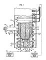
- the fluidized bed calciner is referred to generally as 20 and comprises a vertical substantially cylindrical inner shell 30 which may be Schedule 40 304 stainless steel.
- the inner shell 30 may be approximately 3 inches in inside diameter or substantially larger in inside diameter and sealed at the top-most end thereof by a top closure plate (not shown), which may be welded to inner shell 30, except for a product output port (not shown) provided in the closure plate for exit of the calcined product from the fluidized bed calciner 20.
- a bottom end cap 40 Extending across the bottom-most end of inner shell 30 and attached thereto, which may be by welding, is a bottom end cap 40, which may be stainless steel, having a conically-shaped inside surface 50 for receiving a substantially circular and horizontal fluidized bed support member 60 and defining a larger diameter 70 at the top end of the conically-shaped inside surface 50 and a smaller diameter 80 at the bottm end thereof.
- a substantially cylindrical first cavity 90 which extends from the smaller diameter 80 to an end plate 100 and terminates thereat.
- the member 60 Extending across and disposed on the inside surface 50 is the member 60, which may be stainless steel, in communication with a fluidized bed 110 and disposed on the inside surface 50 such that the circumferential edge of member 60 abuts the wall of the inside surface 50 for supporting bed 110 and for providing uniform rectangular slots 120 (see Fig. 2) for uniform gas flow to the bed 110.
- the member 60 is supported from below by a vertical tubular plate support mast 130, which may be stainless steel, secured, which may be by welding, to support member 60 at the top-most end of mast 130 and secured to end plate 100 at the bottom-most end thereof, wherein the end plate 100 substantially seals inner shell 30.
- the support mast 130 extends vertically from end plate 100, through the first cavity 90 and to member 60.
- disposed in fluidized bed 110 is a plurality of spherical beads 140, which may be Inconel 625 and approximately 1 mm in diameter, to provide a heat transfer surface area for uniform fine-grain powder formation and to inhibit in-process product holdup.
- the beads 140 are larger than the slots 120 (see Fig. 2), which are disposed in support member 60, so that the beads 140 do not pass downwardly through the slots 120 and thereafter plug a fluidizing gas orifice 150 or first cavity 90.
- Gas orifice 150 is disposed in one end of a fluidizing gas first conduit 151 which is connected to a first gas supply means (not shown) at one end thereof and to first cavity 90 at the other end thereof for providing a path for fluidizing gas flow from first gas supply means to first cavity 90.
- the beads 140 which may comprise a total volume approximately of 800 cubic centimeters or substantially greater, are sprayed with feed material, such as ammonium diuranate slurry or uranyl nitrate solution or toxic waste, from a feed nozzle generally designated by numeral 160.
- feed material such as ammonium diuranate slurry or uranyl nitrate solution or toxic waste
- the powder separates from the surfaces of the beads 140 due to the operation of an internal jet grinder nozzle (not shown) and due to the bouncing motion of the beads 140 induced by the upwardly force of the fluidizing gas which conveys the powder to the product output port.
- Disposed in the upper portion of inner shell 30 is a plurality of baffles (not shown) for creating barriers to prevent the bouncing beads 140 from leaving the inner shell 30 through the product output port.
- the jet grinder nozzle Disposed in the lower portion of inner shell 30 and downstream of feed nozzle 160 is the jet grinder nozzle (not shown) which is in communication with a second gas supply means (not shown) such as a traditional gas supply means device for minimizing the accumulation of converted solids on the beads 140 disposed in bed 110.
- a gas which may be air preheated to approximately 400°C, flows from the second gas supply means device through the jet grinder nozzle to the bed 110 and impinges the beads 140 against a target plate (not shown), which may be a stainless steel square approximately 0.5 inch on each side, with sufficient force to dislodge the converted solids from the surfaces of the beads 140 thereby minimizing accumulation of converted solids on the beads 140 so that heat transfer occurs between the beads 140 and the feed material being calcined.
- an electric current which flows from an electrical source, passes through a plurality of vertical tubular internal heaters 180 which are disposed in the lower portion of inner shell 30 and which are in communication with fluidized bed 110 for heating fluidized bed 110 by heat conduction and radiation.
- Connectors (not shown) are dispsed on the base portion of each internal heater 180 and are configured to aid in installation and removal of each internal heater 180.
- the lower portion of each internal heater 180 is disposed in a second cavity 190.
- Electric current which flows from an electrical source, passes through a plurality of external heaters 200 disposed circumferentially about the outside length of inner shell 30 for heating inner shell 30 thereby heating bed 110 by heat conduction and radiation.
- external heaters 200 there may be 13 external heaters 200, such as Calrod band heaters available from Watlow Electric Company located in St. Louis, Missouri, each dissipating 1 KW of electric power.
- Disposed about external heaters 200 is a vertical substantially cylindrical outer shell 210 for providing radiative heat reflection from the external heaters back to inner shell 30.
- thermocouples 181 Disposed in internal heaters 180 are a plurality of first thermocouples 181 for sensing bed 110 temperature and having a temperature shut-off means 182 for turning-off heaters 180 when bed 110 temperature exceeds a predetermined maximum.
- a second thermocouple (not shown) is disposed near the top of the beads 140.
- the second thermocoupe is connected to external heaters 200 and to a temperature control means 220 for controlling bed 110 operating temperature to within plus or minus approximately 25°C of the desired bed 110 operating temperature.
- the combination of internal heaters 180, external heaters 200, and temperature control means 220 maintains the bed 110 at a desired operating temperature which is preferably between approximately 400°C and 700°C plus or minus approximately 25°C of the desired bed 110 operating temperature.
- a plurality of parallel first channels 230 traverse the top surface of member 60 and extend from one circumferential edge of member 60 to the other edge thereof and extend from the top surface of member 60 to the bottom surface thereof except where first channels 230 intersect a plurality of parallel substantially rectangular second ridges 250 which define a plurality of parallel second channels 260.
- Second channels 260 traverse the bottom surface of member 60 and extend from one circumferential edge of member 60 to the other edge thereof and extend from the bottom surface of member 60 to the top surface thereof except where second channels 260 intersect first ridges 240.
- the second channels 260 are arranged perpendicularly to first channels 230, which arrangement forms a through-member checkerboard lattice of rectangular slots 120.
- the first channels 230 and the second channels 260 may be formed by simultaneous machining on the top and bottom surfaces of a one-piece metal blank which may be stainless steel.
- the slots 120 uniformly direct gas flow to bed 110 which is disposed downstream of member 60 and which is in communication with member 60.
- the gas which may be nitrogen, flows upwardly from the gas orifice 150 through first cavity 90, through slots 120 and to bed 110 for fluidizing bed 110. Uniform gas flow through member 60 is achieved by the approximate equidistant and uniform placement of the slots 120.
- each slot 120 is smaller than the minimum diameter of any bead 140 for preventing the beads 140 from passing downwardly through the slots 120 and plugging the gas orifice 150.
- the uniform gas flow and beads 140 aid uniform heat transfer within bed 110 thereby producing product output of approximately uniform consistency of calcination and powder particulate size.
- support member 60 may comprise parallel first bars extending from one circumferential edge of support member 60 to the other edge thereof and parallel second bars extending from one circumferential edge of support member 60 to the other edge thereof, the intersection of the first bars and the second bars defining a lattice of slots for directing uniform or non-uniform gas flow from the gas orifice 150 to fluidized bed 110.
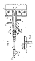
- feed nozzle 160 which is disposed through the outer shell 210 and the inner shell 30 downstream of member 60 for delivering feed material to bed 110 from a feed material supply conduit 299 that is connected to a feed material supply means.
- Feed nozzle 160 which may be stainless steel, comprises a body 290 with an inlet orifice 300 disposed in one end of body 290 and with an outlet orifice 310 disposed in the other end thereof. Extending from inlet orifice 300 to outlet orifice 310 is a continuous third cavity 320 through which third cavity 320 feed material flows to fluidized bed 110.
- the third cavity 320 also serves as a conduit for delivering a cleaning chemical to cavity 320, outlet orifice 310 and beads 140.
- Cleaning of beads 140, outlet orifice 310 and third cavity 320 may be performed with the cleaning chemical following completion of calcination.
- the cleaning chemical which may be nitric acid solution or water, chemically scrubs the beads 140 of residual feed material and removes feed material from outlet orifice 310 and from third cavity 320 when the beads 140 are refluidized following completion of a previous calcination.
- a hollow tubular feed means 319 which may be stainless steel, is inserted through inlet orifice 300 and into third cavity 320 to approximately 0.25 inch from outlet orifice 310, for delivering the feed material or the cleaning chemical into third cavity 320.
- feed means 319 defines an annulus 340 between the exterior surface of feed means 319 and the interior wall of third cavity 320.
- a cleaner supply conduit 350 one end of which is connected to a cleaner supply means, is connected to feed means 319.
- the conduit 350 utilizes the cleaning chemical for chemically scrubbing the beads 140 and for flushing outlet orifice 310, third cavity 320, and feed means 319.
- a continuous duct 360 extending from the exterior surface of body 290 to the annulus 340.
- the duct 360 provides a path for gas flow to annulus 340.
- a third gas supply conduit 361 Connected to duct 360 and external to body 290 is a third gas supply conduit 361 that is connected to a third gas supply means, which third gas supply means provides a gas such as nitrogen that flows from the third gas supply means through third conduit 361, through duct 360, through annulus 340 and to third cavity 320 for conveying the feed material from third cavity 320 to outlet orifice 310.
- the body 290 is cooled to approximately 50°C by a cooling means 370 disposed therein for preventing precalcination of feed material at outlet orifice 310.
- the cooling means 370 may be an annular region through which flows a coolant such as water. Alternatively, the cooling means 370 may be disposed circumferentially or longitudinally about the outside surface of body 290.
- an electric current is supplied from an electrical source to the internal heaters 180 and to the external heaters 200.
- the internal heaters 180 which are disposed in inner shell 30, and the external heaters 200, which are disposed circumferentially about the outside length of inner shell 30 heat bed 110 by conductive and radiative heat transfer. Disposed in internal heaters 180 are the plurality of first thermocouples 181 for sensing bed 110 temperature, first theremocouples 181 having the temperature shut-off means 182 for turning-off heaters 180 when bed 110 temperature exceeds a predetermined maximum.
- the second thermocouple which is disposed near the top of beads 140 is connected to external heaters 200 and to the temperature control means 220 for controlling bed 110 operating temperature to within plus or minus approximately 25°C of the desired bed 110 operating temperature.
- preheated fluidizing gas which may be preheated to approximately 350°C or substantially higher, flows from the fluidizing gas orifice 150 which is connected to the first gas supply conduit 151 upstream of member 60.
- the preheated gas flows upwardly through the slots 20 disposed in support member 60.
- the upwardly force of the fluidizing gas agitates the beads 140 disposed downstream of support member 60 causing the beads 140 to bounce within inner shell 30.
- a slurry or a solution feed material enters feed means 319 and passes into cavity 320 which is disposed in body 290.
- Gas flows from the third gas supply conduit 361 through duct 360 to annulus 340 for conveying the feed material from cavity 320 to outlet orifice 310 and for spraying the feed material into bed 110.
- the coolant flows through cooling means 370 which is disposed in body 290 for cooling body 290.
- the internal jet grinder nozzle supplies preheated gas to bed 110 from the second gas supply means for minimizing accumulation of converted solids on the beads 140 in bed 110 thereby aiding in conductive and radiative heat transfer from the beads 140 to the feed material undergoing calcination.
- the beads 140 are sprayed with feed material from feed nozzle 160, the resulting aggregation of beads 140 and feed material forming the substance of the bed 110.
- the presence of the annulus 340 and the force of the gas flow issuing from annulus 340 mitigate plugging of outlet orifice 310 with feed material.
- the fluidized bed 110 is heated by internal heaters 180 and external heaters 200.
- the feed material being calcined in the fluidized bed 110 is turned into powder-like particulates by the application of heat from the internal heaters 180 and external heaters 200 whereby the temperature of bed 110 is below the melting point of the feed material yet high enough to release carbon dioxide and to remove bound water and other volatile impurities.
- the beads 140 which also float upwardly due to the force of the fluidizing gas, impinge on the baffles, which are disposed in the upper portion of inner shell 30 upstream of the product output port, and fall downwardly to the fluidized bed 110. Consequently, the baffles act as barriers for preventing the beads 140 from exiting the calciner through the product output port and allow the calcined product to carry over to the product output port.
- the invention provides a fluidized bed calciner capable of remotely calcining hazardous materials and possessing a means to clean the feed nozzle and fluidized bed following completion of calcination and possessing a means to restart fluidization at will.
Landscapes
- Chemical & Material Sciences (AREA)
- Engineering & Computer Science (AREA)
- Combustion & Propulsion (AREA)
- Organic Chemistry (AREA)
- Chemical Kinetics & Catalysis (AREA)
- Physics & Mathematics (AREA)
- General Engineering & Computer Science (AREA)
- High Energy & Nuclear Physics (AREA)
- Devices And Processes Conducted In The Presence Of Fluids And Solid Particles (AREA)
- Crucibles And Fluidized-Bed Furnaces (AREA)
- Feeding, Discharge, Calcimining, Fusing, And Gas-Generation Devices (AREA)
Applications Claiming Priority (2)
| Application Number | Priority Date | Filing Date | Title |
|---|---|---|---|
| US90806986A | 1986-09-16 | 1986-09-16 | |
| US908069 | 1986-09-16 |
Publications (2)
| Publication Number | Publication Date |
|---|---|
| EP0260377A2 true EP0260377A2 (fr) | 1988-03-23 |
| EP0260377A3 EP0260377A3 (fr) | 1989-03-29 |
Family
ID=25425116
Family Applications (1)
| Application Number | Title | Priority Date | Filing Date |
|---|---|---|---|
| EP87105708A Ceased EP0260377A3 (fr) | 1986-09-16 | 1987-04-16 | Four de calcination à lit fluidifié |
Country Status (2)
| Country | Link |
|---|---|
| EP (1) | EP0260377A3 (fr) |
| JP (1) | JPS6383579A (fr) |
Cited By (2)
| Publication number | Priority date | Publication date | Assignee | Title |
|---|---|---|---|---|
| EP0277208A4 (fr) * | 1986-08-14 | 1988-11-28 | United States Gypsum Co | Calcination a rendement eleve de gypse en hemihydrate. |
| EP0327383A3 (fr) * | 1988-02-05 | 1990-01-10 | Exxon Research And Engineering Company | Réservoir contenant une grille pourvue d'une bordure de support en forme conique |
Family Cites Families (6)
| Publication number | Priority date | Publication date | Assignee | Title |
|---|---|---|---|---|
| US2614034A (en) * | 1947-02-01 | 1952-10-14 | Foster Wheeler Corp | Catalyst vessel |
| US2977194A (en) * | 1958-12-03 | 1961-03-28 | John W Loeding | Method of reducing aqueous radioactive nuclear wastes to solid form |
| DE1442600A1 (de) * | 1965-10-15 | 1969-08-28 | Bergwerksverband Gmbh | Anstroemboden fuer Wirbelbetten |
| JPS5683396A (en) * | 1979-12-07 | 1981-07-07 | Matsushita Electric Industrial Co Ltd | Detector for water level of washing machine doubling as hydroextracting |
| JPS56108090A (en) * | 1980-01-31 | 1981-08-27 | Kawasaki Steel Co | Gas blowinggin nozzle for heat medium particle circulation fluid layer |
| JPS5747726A (en) * | 1980-09-02 | 1982-03-18 | Mitsui Petrochem Ind Ltd | Manufacturing apparatus for uranium trioxide |
-
1987
- 1987-04-16 EP EP87105708A patent/EP0260377A3/fr not_active Ceased
- 1987-05-15 JP JP11996687A patent/JPS6383579A/ja active Pending
Cited By (2)
| Publication number | Priority date | Publication date | Assignee | Title |
|---|---|---|---|---|
| EP0277208A4 (fr) * | 1986-08-14 | 1988-11-28 | United States Gypsum Co | Calcination a rendement eleve de gypse en hemihydrate. |
| EP0327383A3 (fr) * | 1988-02-05 | 1990-01-10 | Exxon Research And Engineering Company | Réservoir contenant une grille pourvue d'une bordure de support en forme conique |
Also Published As
| Publication number | Publication date |
|---|---|
| JPS6383579A (ja) | 1988-04-14 |
| EP0260377A3 (fr) | 1989-03-29 |
Similar Documents
| Publication | Publication Date | Title |
|---|---|---|
| US4476098A (en) | Microwave heated fluidized bed reactor having stages | |
| US4755138A (en) | Fluidized bed calciner apparatus | |
| JPH11513967A (ja) | 原子力産業における金属酸化物硝酸塩からの粉末状金属酸化物混合物を生成する方法 | |
| US4152287A (en) | Method for calcining radioactive wastes | |
| EP0260377A2 (fr) | Four de calcination à lit fluidifié | |
| GB1576657A (en) | Dry reprocessing of irradiated nuclear fuels | |
| EP3356567B1 (fr) | Procédé et appareil pour produire de l'uranium ou un élément terre rare | |
| EP0047624B1 (fr) | Réacteur et procédé de préparation de trioxyde d'uranium et/ou d'oxyde de plutonium | |
| JPS5847039B2 (ja) | 核燃料の処理方法及び核方法に用いる処理装置 | |
| JP2017142210A (ja) | 放射性廃棄物の減容処理装置及び減容処理方法 | |
| RU144530U1 (ru) | Установка для термохимической обработки облученного ядерного топлива | |
| US3756786A (en) | Fuel elements of graphite moderated high temperature reactors process and apparatus for the recovery of nuclear fuel material from | |
| US3671199A (en) | Plutonium hexafluoride reduction | |
| JPS5826033A (ja) | 硝酸ウラニルまたは/および硝酸プルトニウムの脱硝装置 | |
| RU2599670C1 (ru) | Способ переработки раствора уранилнитрата на оксид урана и раствор азотной кислоты и устройство для его осуществления | |
| RU2601765C1 (ru) | Способ получения оксида урана из раствора уранилнитрата и устройство для его осуществления | |
| RU2181072C1 (ru) | Реактор для переработки хлорорганических соединений | |
| JPS6144811B2 (fr) | ||
| JPS6031766B2 (ja) | 硝酸ウラニルまたは/および硝酸プルトニウムの脱硝装置 | |
| Bjorklund et al. | Method for calcining radioactive wastes | |
| Dickey et al. | High-level waste solidification: applicability of fluidized-bed calcination to commercial wastes | |
| Park et al. | A study on improvement of UO {sub 2} powder production process for high sintered density | |
| JPH0236527B2 (ja) | Akuchinoidoshosankabutsunonetsubunkaihannosochi | |
| JPS6238285B2 (fr) | ||
| Heidt et al. | The use of fluid bed equipment in enriched uranium processing |
Legal Events
| Date | Code | Title | Description |
|---|---|---|---|
| PUAI | Public reference made under article 153(3) epc to a published international application that has entered the european phase |
Free format text: ORIGINAL CODE: 0009012 |
|
| AK | Designated contracting states |
Kind code of ref document: A2 Designated state(s): DE ES FR GB IT |
|
| PUAL | Search report despatched |
Free format text: ORIGINAL CODE: 0009013 |
|
| AK | Designated contracting states |
Kind code of ref document: A3 Designated state(s): DE ES FR GB IT |
|
| 17P | Request for examination filed |
Effective date: 19890825 |
|
| 17Q | First examination report despatched |
Effective date: 19900531 |
|
| STAA | Information on the status of an ep patent application or granted ep patent |
Free format text: STATUS: THE APPLICATION HAS BEEN REFUSED |
|
| 18R | Application refused |
Effective date: 19901208 |
|
| RIN1 | Information on inventor provided before grant (corrected) |
Inventor name: OWEN, THOMAS JR. Inventor name: KLEM, MICHAEL J., JR. Inventor name: CASH, ROBERT JAMES |