EP0260384A2 - Dispositif de coupe à lame de scie à entraînement oscillant - Google Patents
Dispositif de coupe à lame de scie à entraînement oscillant Download PDFInfo
- Publication number
- EP0260384A2 EP0260384A2 EP87108026A EP87108026A EP0260384A2 EP 0260384 A2 EP0260384 A2 EP 0260384A2 EP 87108026 A EP87108026 A EP 87108026A EP 87108026 A EP87108026 A EP 87108026A EP 0260384 A2 EP0260384 A2 EP 0260384A2
- Authority
- EP
- European Patent Office
- Prior art keywords
- saw blade
- tool
- web
- holder
- plastic
- Prior art date
- Legal status (The legal status is an assumption and is not a legal conclusion. Google has not performed a legal analysis and makes no representation as to the accuracy of the status listed.)
- Withdrawn
Links
Images

Classifications
-
- B—PERFORMING OPERATIONS; TRANSPORTING
- B23—MACHINE TOOLS; METAL-WORKING NOT OTHERWISE PROVIDED FOR
- B23D—PLANING; SLOTTING; SHEARING; BROACHING; SAWING; FILING; SCRAPING; LIKE OPERATIONS FOR WORKING METAL BY REMOVING MATERIAL, NOT OTHERWISE PROVIDED FOR
- B23D45/00—Sawing machines or sawing devices with circular saw blades or with friction saw discs
- B23D45/16—Hand-held sawing devices with circular saw blades
- B23D45/165—Hand-held sawing devices with circular saw blades with a plurality of saw blades or saw blades having plural cutting zones
-
- B—PERFORMING OPERATIONS; TRANSPORTING
- B23—MACHINE TOOLS; METAL-WORKING NOT OTHERWISE PROVIDED FOR
- B23D—PLANING; SLOTTING; SHEARING; BROACHING; SAWING; FILING; SCRAPING; LIKE OPERATIONS FOR WORKING METAL BY REMOVING MATERIAL, NOT OTHERWISE PROVIDED FOR
- B23D47/00—Sawing machines or sawing devices working with circular saw blades, characterised only by constructional features of particular parts
- B23D47/04—Sawing machines or sawing devices working with circular saw blades, characterised only by constructional features of particular parts of devices for feeding, positioning, clamping, or rotating work
- B23D47/042—Sawing machines or sawing devices working with circular saw blades, characterised only by constructional features of particular parts of devices for feeding, positioning, clamping, or rotating work for conveying work to, or discharging work from, the machine
-
- B—PERFORMING OPERATIONS; TRANSPORTING
- B27—WORKING OR PRESERVING WOOD OR SIMILAR MATERIAL; NAILING OR STAPLING MACHINES IN GENERAL
- B27B—SAWS FOR WOOD OR SIMILAR MATERIAL; COMPONENTS OR ACCESSORIES THEREFOR
- B27B19/00—Other reciprocating saws with power drive; Fret-saws
- B27B19/006—Other reciprocating saws with power drive; Fret-saws with oscillating saw blades; Hand saws with oscillating saw blades
-
- B—PERFORMING OPERATIONS; TRANSPORTING
- B27—WORKING OR PRESERVING WOOD OR SIMILAR MATERIAL; NAILING OR STAPLING MACHINES IN GENERAL
- B27B—SAWS FOR WOOD OR SIMILAR MATERIAL; COMPONENTS OR ACCESSORIES THEREFOR
- B27B19/00—Other reciprocating saws with power drive; Fret-saws
- B27B19/006—Other reciprocating saws with power drive; Fret-saws with oscillating saw blades; Hand saws with oscillating saw blades
- B27B19/008—Other reciprocating saws with power drive; Fret-saws with oscillating saw blades; Hand saws with oscillating saw blades having a plurality of saw blades or saw blades having plural cutting zones
-
- B—PERFORMING OPERATIONS; TRANSPORTING
- B27—WORKING OR PRESERVING WOOD OR SIMILAR MATERIAL; NAILING OR STAPLING MACHINES IN GENERAL
- B27B—SAWS FOR WOOD OR SIMILAR MATERIAL; COMPONENTS OR ACCESSORIES THEREFOR
- B27B5/00—Sawing machines working with circular or cylindrical saw blades; Components or equipment therefor
- B27B5/29—Details; Component parts; Accessories
- B27B5/30—Details; Component parts; Accessories for mounting or securing saw blades or saw spindles
- B27B5/34—Devices for securing a plurality of circular saw blades on a single saw spindle; Equipment for adjusting the mutual distance
Definitions
- Power tools with an oscillating drive are already known, which have a saw blade on their output shaft.
- Devices of this type are used, among other things, as hand cutting machines for fabrics, plastic sheets or the like.
- hand cutting machines for fabrics, plastic sheets or the like.
- the task The present invention is to provide a cutting tool of the type described above, in which any damage to the lower material is excluded.
- the holder carrying the bar In order to avoid jamming when cutting, the holder carrying the bar must not be stronger than the saw blade. As a result, there is a risk that the relatively thin holder will bend when handled carelessly and the web will become jammed on the saw blade or shift laterally to the extent that it no longer offers protection.
- two approximately identical saw blades are therefore arranged on the same drive shaft according to a further feature of the invention, with a common or two individual webs being arranged for both saw blades.
- the width of the holder can now be twice the material thickness of the saw blade plus a possible distance between the two blades. By increasing the distance accordingly, any strength of the holder can be achieved within certain limits.
- the material loss to be accepted due to the resulting chip is irrelevant, since it is only packaging material, which is no longer used. Particularly favorable conditions are achieved if the holder is arranged between the two saw blades.
- the protective housing covering the saw blade in this tool is preferably, as seen in the working direction, bevelled from the front upward to the rear downward toward the working area, in order to allow immersion when the material is first cut. Only then is the tool swiveled into its actual working position.
- the web is preferably slit lengthways or, if two webs are used, a distance is provided between them.
- a suction device is provided on the protective housing, which is used to suction the sawdust.
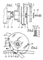
- the cutting tool 1 consists of the two housing parts 2 and 3, the saw blades 4 and 5, the holder 6 with the web 7, the spacer 8, the washer 9 and the screw 10.
- To attach the cutting tool 1 to the oscillating drive machine 11 are first the housing part 2 is pushed onto the shaft 12 and then the saw blade 4 onto the drive shaft 13. Then the holder 6 is placed on the housing part 2, whereupon the spacer 8 with the saw blade 5 is placed on the drive shaft 13. Then the housing part 3 is placed on the housing part 2 and connected to it by screws 14. The holder 6 is clamped between the two housing parts. The two saw blades 4 and 5 are fixed by the fastening screw 10 which can be screwed into the drive shaft 13 with the interposition of the disc 9.
- Fig. 2 shows the tool in use.
- the material web 15 is cut here.
- the housing 2, 3 initially has a bevel 16, which, viewed in the working direction 17, runs from the front upward to the rear downward, so that when cutting the material with the aid of the bevel, it can first be immersed in it. Then the tool is then in the drawn position turned.
- the web 7 covers the saw blades 4 and 5 below the actual work area 18 and engages under the web 15, so that material lying underneath cannot be damaged.
- the web 7 also has a slot 19 through which the chip 20 separated by the saw blades 4 and 5 can exit.
- FIGS. 4 and 5 show a cutting tool 1, in which a suction device 21 is attached.
- the suction device 21 consists of a nozzle 22 which is fastened with its tabs 23 to the holder 6 by means of screws 24.
- the wall of the housing parts 2 and 3 is broken, so that the chips from the web 7 through the housing parts 2 and 3 and through the connector 22 through a hose 25 from one suction unit not shown in the drawing.
Landscapes
- Life Sciences & Earth Sciences (AREA)
- Engineering & Computer Science (AREA)
- Mechanical Engineering (AREA)
- Wood Science & Technology (AREA)
- Forests & Forestry (AREA)
- Sawing (AREA)
- Auxiliary Devices For And Details Of Packaging Control (AREA)
- Knives (AREA)
Applications Claiming Priority (2)
| Application Number | Priority Date | Filing Date | Title |
|---|---|---|---|
| DE19863631734 DE3631734A1 (de) | 1986-09-18 | 1986-09-18 | Schneidwerkzeug mit oszillierend antreibbarem saegeblatt |
| DE3631734 | 1986-09-18 |
Publications (2)
| Publication Number | Publication Date |
|---|---|
| EP0260384A2 true EP0260384A2 (fr) | 1988-03-23 |
| EP0260384A3 EP0260384A3 (fr) | 1989-12-13 |
Family
ID=6309833
Family Applications (1)
| Application Number | Title | Priority Date | Filing Date |
|---|---|---|---|
| EP87108026A Withdrawn EP0260384A3 (fr) | 1986-09-18 | 1987-06-03 | Dispositif de coupe à lame de scie à entraínement oscillant |
Country Status (3)
| Country | Link |
|---|---|
| EP (1) | EP0260384A3 (fr) |
| JP (1) | JPS6377481A (fr) |
| DE (1) | DE3631734A1 (fr) |
Cited By (4)
| Publication number | Priority date | Publication date | Assignee | Title |
|---|---|---|---|---|
| DE102006025068A1 (de) * | 2006-05-23 | 2007-11-29 | C. & E. Fein Gmbh | Sägeblatt mit Abdeckung für Oszillationsantrieb |
| GB2495207A (en) * | 2011-09-30 | 2013-04-03 | Bosch Gmbh Robert | Circular saw guard system |
| US10137592B2 (en) | 2013-05-06 | 2018-11-27 | Milwaukee Electric Tool Corporation | Oscillating multi-tool system |
| CN109414798A (zh) * | 2016-07-15 | 2019-03-01 | 喜利得股份公司 | 用于工具设备的吸尘罩 |
Families Citing this family (2)
| Publication number | Priority date | Publication date | Assignee | Title |
|---|---|---|---|---|
| DE19613538C1 (de) * | 1996-04-03 | 1997-07-10 | Engelbert Gmeilbauer | Schneidmesser |
| JP4578983B2 (ja) * | 2005-01-11 | 2010-11-10 | オルファ株式会社 | スラッシュキルト用のカッターナイフ |
Family Cites Families (8)
| Publication number | Priority date | Publication date | Assignee | Title |
|---|---|---|---|---|
| DE505274C (de) * | 1930-08-16 | Max Niederhofer | Gipsverbandoeffner | |
| US2139272A (en) * | 1936-08-04 | 1938-12-06 | Charles N Jaworski | Saw for removing plaster casts |
| DE1645426U (de) * | 1952-08-14 | 1952-10-16 | Krauss & Reichert | Stoffzuschneidemaschine mit umlaufenden messerscheiben. |
| DE1763428U (de) * | 1957-12-19 | 1958-03-20 | Besmer Teppichfabrik G M B H | Schneidgeraet fuer fussbodenbelag, insbesondere auslegeware. |
| DE1797711U (de) * | 1959-06-25 | 1959-10-15 | Emil Hoogland Fa | Stoffzuschneidemaschine. |
| US3670412A (en) * | 1970-09-28 | 1972-06-20 | Frank W Cunningham | Power cutter |
| DE2152200A1 (de) * | 1971-10-20 | 1973-04-26 | Otto Maier | Gipsverband-trennvorrichtung |
| US4625405A (en) * | 1984-07-02 | 1986-12-02 | Deeco, Inc. | Cast cutter |
-
1986
- 1986-09-18 DE DE19863631734 patent/DE3631734A1/de not_active Ceased
-
1987
- 1987-06-03 EP EP87108026A patent/EP0260384A3/fr not_active Withdrawn
- 1987-07-29 JP JP62187873A patent/JPS6377481A/ja active Pending
Cited By (9)
| Publication number | Priority date | Publication date | Assignee | Title |
|---|---|---|---|---|
| DE102006025068A1 (de) * | 2006-05-23 | 2007-11-29 | C. & E. Fein Gmbh | Sägeblatt mit Abdeckung für Oszillationsantrieb |
| GB2495207A (en) * | 2011-09-30 | 2013-04-03 | Bosch Gmbh Robert | Circular saw guard system |
| US9089941B2 (en) | 2011-09-30 | 2015-07-28 | Robert Bosch Gmbh | Circular saw guard system |
| GB2495207B (en) * | 2011-09-30 | 2017-05-31 | Bosch Gmbh Robert | Circular saw guard system |
| US10137592B2 (en) | 2013-05-06 | 2018-11-27 | Milwaukee Electric Tool Corporation | Oscillating multi-tool system |
| US10940605B2 (en) | 2013-05-06 | 2021-03-09 | Milwaukee Electric Tool Corporation | Oscillating multi-tool system |
| US11724413B2 (en) | 2013-05-06 | 2023-08-15 | Milwaukee Electric Tool Corporation | Oscillating multi-tool system |
| US12179378B2 (en) | 2013-05-06 | 2024-12-31 | Milwaukee Electric Tool Corporation | Oscillating multi-tool system |
| CN109414798A (zh) * | 2016-07-15 | 2019-03-01 | 喜利得股份公司 | 用于工具设备的吸尘罩 |
Also Published As
| Publication number | Publication date |
|---|---|
| DE3631734A1 (de) | 1988-04-07 |
| EP0260384A3 (fr) | 1989-12-13 |
| JPS6377481A (ja) | 1988-04-07 |
Similar Documents
| Publication | Publication Date | Title |
|---|---|---|
| DE3005860A1 (de) | Handwerkzeugmaschine, insbesondere blechnager | |
| DE3734013C1 (de) | Handwerkzeugmaschine mit hin- und herbewegbarem,spangebendem Werkzeug | |
| EP0005726A1 (fr) | Outil de coupe pour machine à hacher les aliments | |
| DE3717585C2 (fr) | ||
| EP0260384A2 (fr) | Dispositif de coupe à lame de scie à entraînement oscillant | |
| AT412956B (de) | Trenngerät | |
| DE899881C (de) | Vorrichtung an Werkzeugmaschinen zum Ausloesen von Schaltvorgaengen, insbesondere zur Unfallverhuetung | |
| DE1777276B2 (de) | Schere, insbesondere blechschere | |
| DE7904242U1 (de) | Tragbares elektrowerkzeug zur spanenden bearbeitung von werkstuecken, insbesondere handsaege oder -fraese | |
| DE19710897A1 (de) | Trennaggregat mit zwei Trennmitteln, insbesondere eine Säge mit zwei Sägeblättern | |
| EP3812101B1 (fr) | Dispositif d'aspiration | |
| DE1627233C3 (de) | Fliegende Schere zum Abtrennen von Draht- oder Bandabschnitten | |
| EP3812100A1 (fr) | Machine-outil à main électrique | |
| DE9315498U1 (de) | Hubsäge | |
| DE202016103612U1 (de) | Schleifbandaufnahmeadapter für Dekupiermaschinen | |
| DE1031954B (de) | Abschirmvorrichtung fuer umlaufende Schneidwerkzeuge fuer die Holzbearbeitung | |
| DE1627222A1 (de) | Werkzeug zur Feinbearbeitung von Bohrungen,insbesondere Reibahle | |
| DE202010017556U1 (de) | Faserschneidvorrichtung | |
| DE321603C (de) | Handschneidewerkzeug zum Entfernen des Abfalls von Vorspinnspulen | |
| DE19612482C1 (de) | Kleinfräsenvorsatz | |
| WO2024068296A1 (fr) | Scie circulaire | |
| DE834381C (de) | Handgeraet zum Zuschneiden von flaechenfoermigen Gebilden | |
| DE29910049U1 (de) | Heckenschere | |
| DE8505062U1 (de) | Messerkopf für eine Fleischschneidemaschine | |
| DE815708C (de) | Lochungsvorrichtung fuer Kartengeber |
Legal Events
| Date | Code | Title | Description |
|---|---|---|---|
| PUAI | Public reference made under article 153(3) epc to a published international application that has entered the european phase |
Free format text: ORIGINAL CODE: 0009012 |
|
| AK | Designated contracting states |
Kind code of ref document: A2 Designated state(s): CH DE FR GB IT LI NL SE |
|
| PUAL | Search report despatched |
Free format text: ORIGINAL CODE: 0009013 |
|
| AK | Designated contracting states |
Kind code of ref document: A3 Designated state(s): CH DE FR GB IT LI NL SE |
|
| STAA | Information on the status of an ep patent application or granted ep patent |
Free format text: STATUS: THE APPLICATION IS DEEMED TO BE WITHDRAWN |
|
| 18D | Application deemed to be withdrawn |
Effective date: 19891231 |
|
| RIN1 | Information on inventor provided before grant (corrected) |
Inventor name: DIE ERFINDER HABEN AUF IHRE NENNUNG VERZICHTET. |