EP0260423A2 - Support de lunettes pour présentoir - Google Patents
Support de lunettes pour présentoir Download PDFInfo
- Publication number
- EP0260423A2 EP0260423A2 EP87111163A EP87111163A EP0260423A2 EP 0260423 A2 EP0260423 A2 EP 0260423A2 EP 87111163 A EP87111163 A EP 87111163A EP 87111163 A EP87111163 A EP 87111163A EP 0260423 A2 EP0260423 A2 EP 0260423A2
- Authority
- EP
- European Patent Office
- Prior art keywords
- holder according
- coupling component
- eyeglass
- cross member
- glasses
- Prior art date
- Legal status (The legal status is an assumption and is not a legal conclusion. Google has not performed a legal analysis and makes no representation as to the accuracy of the status listed.)
- Withdrawn
Links
- 230000008878 coupling Effects 0.000 claims abstract description 26
- 238000010168 coupling process Methods 0.000 claims abstract description 26
- 238000005859 coupling reaction Methods 0.000 claims abstract description 26
- 239000011521 glass Substances 0.000 claims abstract description 23
- 238000003780 insertion Methods 0.000 claims abstract description 10
- 230000037431 insertion Effects 0.000 claims abstract description 10
- 238000004873 anchoring Methods 0.000 claims description 6
- 238000005034 decoration Methods 0.000 description 2
- 230000002349 favourable effect Effects 0.000 description 2
- 238000005452 bending Methods 0.000 description 1
- 230000001419 dependent effect Effects 0.000 description 1
- 229920003023 plastic Polymers 0.000 description 1
- 239000007787 solid Substances 0.000 description 1
Images

Classifications
-
- A—HUMAN NECESSITIES
- A47—FURNITURE; DOMESTIC ARTICLES OR APPLIANCES; COFFEE MILLS; SPICE MILLS; SUCTION CLEANERS IN GENERAL
- A47F—SPECIAL FURNITURE, FITTINGS, OR ACCESSORIES FOR SHOPS, STOREHOUSES, BARS, RESTAURANTS OR THE LIKE; PAYING COUNTERS
- A47F7/00—Show stands, hangers, or shelves, adapted for particular articles or materials
- A47F7/02—Show stands, hangers, or shelves, adapted for particular articles or materials for jewellery, dentures, watches, eye-glasses, lenses, or the like
- A47F7/021—Show stands, hangers, or shelves, adapted for particular articles or materials for jewellery, dentures, watches, eye-glasses, lenses, or the like for eye-glasses
Definitions
- the invention relates to an eyeglass holder for sales stands, each with a support lug supporting the eyeglass bridge and two receiving openings for the eyeglass temples.
- Known sales and exhibition stands for eyeglasses and eyeglass frames usually consist of a supporting column, which can have a round or polygonal cross section and has a plurality of stacking lugs arranged one above the other for the webs of the eyeglasses or eyeglass frames.
- the receiving openings intended for receiving the temple pieces are provided in the wall of the column on both sides of the support lug.
- the object of the invention is therefore to provide an eyeglass holder of the type mentioned at the outset, which enables the eyeglasses or eyeglass frames to be accommodated easily and on all sides and which can be attached to supporting surfaces of very different designs with little effort.
- This object is achieved in that the support lug and two plug-in rings forming the receiving openings are connected to one another by a supporting frame, and in that the supporting frame can be connected to a supporting surface of the sales stand by means of at least one detachable coupling component.
- These eyeglass holders can be attached to very differently designed load-bearing surfaces, for example columns, narrow stands, flat or spatially curved surfaces, spatially curved bands or any other forms that are chosen for reasons of optimal advertising psychology or to adapt to special spatial conditions.
- the surfaces supporting the glasses holder can be formed on special decorative pieces, for example as a sail of a sailboat. In any case, it is sufficient to provide constructive measures for the releasable fastening of the coupling component to the supporting surface, in the simplest case insertion bores which can be provided on any supporting surface with very little effort and in any arrangement.
- this change can be carried out easily and with simple measures. To do this, it is sufficient to remove the glasses holder and to reattach them to a different location and / or in a different arrangement.
- the entire carrying function for the glasses you have taken or glasses frame is taken over by the glasses holder.
- the temples are also completely outside the supporting surface and are therefore fully visible.
- the support frame has a cross member, at both ends of which the plug-in rings are arranged with elongated, vertically extending receiving openings, and that the coupling component engages in the central region of the cross member.
- the coupling components which can be fixed or detachably connected to the support frame, form the sole connection to the supporting surface, on which they are in turn detachably attached.
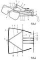
- the glasses holder 1 shown in FIGS. 1, 2 and 3 is formed as a one-piece component from preferably transparent plastic. It is used to hold one pair of glasses 2 or one frame.
- a protruding support lug 3 supports the web of the glasses 2. From the support lug 3, two spars 4 extend obliquely backwards to the two ends of a cross member 5. The spars 4 and the cross member 5 form a triangle in plan.
- the spars 4 can be designed with an opening 6 extending over the entire length in order to reduce weight.
- a plug ring 7 is arranged, which forms an elongated, vertically extending receiving opening 8 for each of the two temple 9.
- the lower edge of the receiving openings 8 is lower than the support surface of the support lug 3, which supports the eyeglass web, so that the glasses 2 are accommodated in a slightly inclined position which is favorable for the presentation.
- the described parts of the spectacle holder 1 form a supporting structure 1 0, which is connected via a coupling member 11 having a supporting surface 12, for example a thin wall provided with bores of the column of a sales stand.
- this load-bearing wall 12 can also be part of another piece of decoration, a wall, a sales or exhibition display case or the like.
- the coupling component 11 has three horizontal plug pins 13 which are integrally connected at one end to the central region of the cross member 5 and each have a longitudinally slotted locking head 14 at their other end, each of which can be inserted and locked into an insertion hole 15 of the supporting surface 12.
- the three locking heads 14 are arranged at the tips of a triangle.
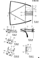
- FIG. 4 differs from the embodiment according to ig F. 1 to 3 only in that the locking heads 14 of the plug pin 13 are not inserted directly into the supporting surface 12, but in Insertion holes 15 each have a front wall 16 of a separate anchoring component 17 (FIG. 5), the rear wall 18 of which has screw holes 19 for screws 19a for fastening the supporting surface 12.
- Insertion holes 15 each have a front wall 16 of a separate anchoring component 17 (FIG. 5), the rear wall 18 of which has screw holes 19 for screws 19a for fastening the supporting surface 12.
- This embodiment is preferred if no insertion bores 15 can or should not be provided in or on the supporting surface 12. This applies in particular if the supporting surface 12 is formed by the outer surface of a solid component, so that the locking heads 14 could not snap into the insertion bores of such a surface 12.
- FIG. 6 differs from the embodiment of FIGS. 1 to 3 only in that the coupling component 11 is designed as a separate component.
- a plate 20 carries on one side the already described elongated plug pins 13 and on the other side slotted locking heads 21 which can be snapped into insertion holes 22 of the cross member 5.
- Such a coupling component 11 is shown in FIG. 7. In FIG. 8, this coupling component of FIG. 7 is combined with the anchoring component 17.
- FIGS. 9 and 10 show coupling components 11, the plate 20 of which is provided on one side with the locking heads 21 which can be snapped into the insertion bores 22 of the cross member 5.
- tabs 23 are formed with screw holes 24, which are used for screw fastening to the supporting surface 12 and are adapted to their shape.
- Fig. 11 shows that in a simplified embodiment, the coupling components 11 can also be designed as rivets 25 or screws 26, which are used to fasten the cross member 5 to the supporting surface 12.
Landscapes
- Eyeglasses (AREA)
Applications Claiming Priority (2)
| Application Number | Priority Date | Filing Date | Title |
|---|---|---|---|
| DE8624761U | 1986-09-16 | ||
| DE19868624761 DE8624761U1 (de) | 1986-09-16 | 1986-09-16 | Brillenhalter für Verkaufsständer |
Publications (2)
| Publication Number | Publication Date |
|---|---|
| EP0260423A2 true EP0260423A2 (fr) | 1988-03-23 |
| EP0260423A3 EP0260423A3 (fr) | 1988-08-24 |
Family
ID=6798345
Family Applications (1)
| Application Number | Title | Priority Date | Filing Date |
|---|---|---|---|
| EP87111163A Withdrawn EP0260423A3 (fr) | 1986-09-16 | 1987-08-03 | Support de lunettes pour présentoir |
Country Status (2)
| Country | Link |
|---|---|
| EP (1) | EP0260423A3 (fr) |
| DE (1) | DE8624761U1 (fr) |
Cited By (1)
| Publication number | Priority date | Publication date | Assignee | Title |
|---|---|---|---|---|
| DE102015007387A1 (de) * | 2015-06-10 | 2016-12-15 | Audi Ag | Haltevorrichtung für eine elektronische Datenbrille und Kraftfahrzeug mit einer Haltevorrichtung |
Families Citing this family (1)
| Publication number | Priority date | Publication date | Assignee | Title |
|---|---|---|---|---|
| DE10053434C2 (de) * | 2000-10-27 | 2003-04-24 | Josef Fent | Haltevorrichtung zum Präsentieren von Brillen |
Family Cites Families (4)
| Publication number | Priority date | Publication date | Assignee | Title |
|---|---|---|---|---|
| US3229944A (en) * | 1964-03-18 | 1966-01-18 | American Optical Corp | Display fixture |
| FR1516143A (fr) * | 1967-01-24 | 1968-03-08 | Panneau porte-outils mural | |
| FR2154998A5 (fr) * | 1971-10-04 | 1973-05-18 | Ridel Jean Francois | |
| FR2199654A5 (fr) * | 1972-09-20 | 1974-04-12 | Seiller Pierre |
-
1986
- 1986-09-16 DE DE19868624761 patent/DE8624761U1/de not_active Expired
-
1987
- 1987-08-03 EP EP87111163A patent/EP0260423A3/fr not_active Withdrawn
Cited By (2)
| Publication number | Priority date | Publication date | Assignee | Title |
|---|---|---|---|---|
| DE102015007387A1 (de) * | 2015-06-10 | 2016-12-15 | Audi Ag | Haltevorrichtung für eine elektronische Datenbrille und Kraftfahrzeug mit einer Haltevorrichtung |
| DE102015007387B4 (de) | 2015-06-10 | 2018-05-03 | Audi Ag | Haltevorrichtung für eine elektronische Datenbrille und Kraftfahrzeug mit einer Haltevorrichtung |
Also Published As
| Publication number | Publication date |
|---|---|
| EP0260423A3 (fr) | 1988-08-24 |
| DE8624761U1 (de) | 1986-12-11 |
Similar Documents
| Publication | Publication Date | Title |
|---|---|---|
| DE3224659C2 (de) | Brillengestell mit elastischem Faden und mit Nasenplättchen | |
| DE69920305T2 (de) | Diebstahlsicherungsmarkierer für Artikel mit stabförmigen Teilen | |
| DE3815889A1 (de) | Displayvorrichtung fuer brillen | |
| DE2342570A1 (de) | Schaugestell fuer brillen | |
| EP0029819A1 (fr) | Rayonnage pour la présentation de chaussures | |
| DE8624761U1 (de) | Brillenhalter für Verkaufsständer | |
| WO2004019304A2 (fr) | Systeme de presentation pour ecran | |
| DE3011562C2 (de) | Kennzeichnungsvorrichtung für Schubladen o.dgl. | |
| DE102007021088B4 (de) | Präsentationseinrichtung, insbesondere für Brillen | |
| DE3118695C2 (de) | Haltevorrichtung für Prospekte u.dgl. | |
| DE20318798U1 (de) | Hakenpolster zur Befestigung von Sonnengläsern an Augengläsern | |
| DE3322161C2 (fr) | ||
| DE3734649A1 (de) | Sportbrille | |
| AT398523B (de) | Ausstellungs- und verkaufsregal | |
| DE102010044332A1 (de) | Vorrichtung zur Aufnahme einer Brille sowie Präsentationsvorrichtung für Brillen | |
| DE1959606A1 (de) | Werbetraeger | |
| DE202010012162U1 (de) | Vorrichtung zur Aufnahme einer Brille sowie Präsentationsvorrichtung für Brillen | |
| DE102010044330A1 (de) | Vorrichtung zur Aufnahme einer Brille sowie Präsentationsvorrichtung für Brillen mit flexibler Kapazität | |
| AT398527B (de) | Reinigungsgerät bestehend aus einer bürste od.dgl. | |
| EP1231587A2 (fr) | Dispositif de securité pour enseigne informative | |
| DE19854556A1 (de) | Vorrichtung zur Präsentation von Brillen | |
| DE9107422U1 (de) | Präsentationshalter für Warenpackungen | |
| DE20103794U1 (de) | Vorrichtung zum Aufstellen einer Armbanduhr | |
| AT400388B (de) | Hinweisvorrichtung für präsentations- oder verkaufsregale od. dgl. | |
| DE3143256A1 (de) | "brillentablett" |
Legal Events
| Date | Code | Title | Description |
|---|---|---|---|
| PUAI | Public reference made under article 153(3) epc to a published international application that has entered the european phase |
Free format text: ORIGINAL CODE: 0009012 |
|
| AK | Designated contracting states |
Kind code of ref document: A2 Designated state(s): AT BE CH DE ES FR GB GR IT LI LU NL SE |
|
| PUAL | Search report despatched |
Free format text: ORIGINAL CODE: 0009013 |
|
| AK | Designated contracting states |
Kind code of ref document: A3 Designated state(s): AT BE CH DE ES FR GB GR IT LI LU NL SE |
|
| 17P | Request for examination filed |
Effective date: 19890224 |
|
| 17Q | First examination report despatched |
Effective date: 19900723 |
|
| STAA | Information on the status of an ep patent application or granted ep patent |
Free format text: STATUS: THE APPLICATION IS DEEMED TO BE WITHDRAWN |
|
| 18D | Application deemed to be withdrawn |
Effective date: 19910205 |
|
| RIN1 | Information on inventor provided before grant (corrected) |
Inventor name: HARTMANN, GERT-ULRICH |