EP0260437A1 - Kassettenladegerät - Google Patents
Kassettenladegerät Download PDFInfo
- Publication number
- EP0260437A1 EP0260437A1 EP87111617A EP87111617A EP0260437A1 EP 0260437 A1 EP0260437 A1 EP 0260437A1 EP 87111617 A EP87111617 A EP 87111617A EP 87111617 A EP87111617 A EP 87111617A EP 0260437 A1 EP0260437 A1 EP 0260437A1
- Authority
- EP
- European Patent Office
- Prior art keywords
- cassette
- side plates
- guide
- loading apparatus
- secured
- Prior art date
- Legal status (The legal status is an assumption and is not a legal conclusion. Google has not performed a legal analysis and makes no representation as to the accuracy of the status listed.)
- Granted
Links
Images


Classifications
-
- G—PHYSICS
- G11—INFORMATION STORAGE
- G11B—INFORMATION STORAGE BASED ON RELATIVE MOVEMENT BETWEEN RECORD CARRIER AND TRANSDUCER
- G11B15/00—Driving, starting or stopping record carriers of filamentary or web form; Driving both such record carriers and heads; Guiding such record carriers or containers therefor; Control thereof; Control of operating function
- G11B15/60—Guiding record carrier
- G11B15/66—Threading; Loading; Automatic self-loading
-
- G—PHYSICS
- G11—INFORMATION STORAGE
- G11B—INFORMATION STORAGE BASED ON RELATIVE MOVEMENT BETWEEN RECORD CARRIER AND TRANSDUCER
- G11B15/00—Driving, starting or stopping record carriers of filamentary or web form; Driving both such record carriers and heads; Guiding such record carriers or containers therefor; Control thereof; Control of operating function
- G11B15/675—Guiding containers, e.g. loading, ejecting cassettes
- G11B15/67544—Guiding containers, e.g. loading, ejecting cassettes with movement of the cassette parallel to its main side and subsequent movement perpendicular thereto, i.e. front loading
- G11B15/67547—Guiding containers, e.g. loading, ejecting cassettes with movement of the cassette parallel to its main side and subsequent movement perpendicular thereto, i.e. front loading the two movements being made by the cassette holder
Definitions
- the present invention relates to a cassette loading apparatus for use in magnetic recording/reproducing apparatuses such as a video tape recorder.
- cassette loading apparatuses for use in magnetic recording/reproducing apparatuses such as a video tape recorder are known and usually employ a so-called front loading system in which a tape cassette is inserted from a front opening.
- a front loading type cassette loading apparatus functions satisfactorily, it requires a number of assembling steps due to its relatively complex structure. For this reason, the cassette loading apparatuses have hitherto been assembled separately from bodies of the magnetic recording/reproducing apparatuses.
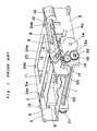
- a prior art cassette loading apparatus includes a cassette holder 1 for detachably holding a tape cassette (not shown) such as a video tape cassette and side plates or side frames 2 and 3 provided at opposite right and left sides of the cassette holder 1.
- a tape cassette such as a video tape cassette
- side plates or side frames 2 and 3 provided at opposite right and left sides of the cassette holder 1.
- L-shaped guide slots 8 and 10 are formed in the right side plate 2
- L-shaped guide slots 9 and 11 are formed in the left side plate 3.
- Projecting pins 4 and 6 are mounted on the right side of the cassette holder 1 so as to be held in engagement with the guide slots 8 and 10 of the right side plate 2, respectively.
- projecting pins 5 and 7 are mounted on the left side of the cassette holder 1 so as to be held in engagement with the guide slots 9 and 11, respectively.
- Drive arms 12 and 13 for moving the cassette holder 1 between a first position and a second position (loading position) is provided at the side plates 2 and 3, respectively. Assuming that the known cassette loading apparatus is placed horizontally, the cassette holder 1 is moved horizontally and vertically as the projecting pins 4, 5, 6 and 7 move along the guide slots 8, 9, 10 and 11, respectively. Reference numerals 4a and 5a show that the projecting pins 4 and 5 are disposed at the second or loading position.
- the drive arm 12 has a toothed portion 12a. Although not specifically shown, the drive arm 13 also has a toothed portion in the same manner as the toothed portion 12a of the drive arm 12.
- a drive motor 16 transmits a driving force, via a worm 17, a worm wheel 18 and a gear 19, to the toothed portion 12a.
- the gear 19 is fixed to one end of a shaft 20 which is rotatably supported by the side plates 2 and 3.
- Another gear 21 is fixed to the other end of the shaft 20 so as to be engaged with the toothed portion of the drive arm 13.
- a cassette guide 22 is provided for guiding the tape cassette when the tape cassette is inserted into the cassette holder 1 and for coupling the side plates 2 and 3 with each other.
- a top plate 23 is provided for coupling the side plates 2 and 3 with each other at an upper portion of the known cassette loading apparatus and for imparting rigidity to the entire known cassette loading apparatus.
- the prior art cassette loading apparatus shown in Fig. 1 is assembled as follows. Initially, the cassette holder 1 and the side plates 2 and 3 are positioned such that the projecting pins 4 to 7 are received in or engaged with the guide slots 8 to 10 of the side plates 2 and 3, respectively. Generally, to this end, the cassette holder 1 is secured to a jig (not shown) and then, the side plates 2 and 3, which are placed accurately at opposite sides of the cassette holder 1, are slowly shifted towards the cassette holder 1 such that the projecting pins 4 to 7 are received in the guide slots 8 to 10, respectively. The drive motor 16, the worm 17 and the worm wheel 18 are attached to the right side plate 2 in advance as a drive unit and description of assembling steps of the drive unit is omitted.
- the gears 19 and 21 are positioned by adjusting engagement of the teeth such that the drive arms 2 and 3 move synchronously with each other.
- the top plate 23 is attached to the side plates 2 and 3 by screws 24a, 24b, 24c and 24d such that large strength and highly accurate assembling of the known cassette loading apparatus are ensured. Thus, assembling of the known cassette loading apparatus is completed.
- the side plates 2 and 3 are required to be slowly shifted towards the cassette holder 1 such that the projecting pins 4 to 7 are, respectively, received in the guide slots 8 to 11 of the side plates 2 and 3.
- a relatively large and and complex jig for assembly is needed.
- the known cassette loading apparatus has been disadvantageous in that a relatively long time period is required for assembling the known cassette loading apparatus.
- the known cassette loading apparatus has such a drawback that after the shaft 20 having the gear 21 secured thereto has been fitted through the side plates 3 and 2, the gear 19 is required to be mounted on the shaft 20 so as to coincide, in arrangement phase, with the gear 21, thereby resulting in low working efficiency in its assembling.
- the present invention has been developed in order to eliminate the above described drawbacks inherent in the conventional cassette loading apparatuses.
- a cassette loading apparatus embodying the present invention comprises: a cassette guide which is provided in the vicinity of an insertion opening of a tape cassette; a cassette holder for holding the tape cassette; a pair of side plates for guiding displacement of said cassette holder, which are provided at opposite sides of said cassette holder, respectively; and a chassis to which said cassette guide is secured; said side plates being mounted on said cassette guide from above such that at least one portion of each of said side plates is secured to said cassette guide, with at least one another portion of each of said side plates being secured to said chassis.
- the cassette loading apparatus is characterized in that a cassette holder can be inserted from above when assembling.
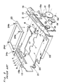
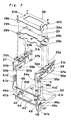
- the cassette loading apparatus includes a cassette holder 25 for detachably holding a tape cassette (not shown) such as a video tape cassette and side plates 26 and 27 provided at opposite right and left sides of the cassette holder 25.
- the side plate 26 is formed with L-shaped guide slots 30a and 31a engageable, respectively, with pins 28a and 29a projecting from a right side face of the cassette holder 25, while the side plate 27 is formed with L-shaped guide slots 30b and 31b engageable, respectively, with pins 28b and 29b projecting from a left side face of the cassette holder 25.
- the side plate 26 is formed, at its upper portion, with recesses 32a and 33a extending from the guide slots 30a and 31a, respectively.
- the side plate 27 is formed, at its upper portion, with recesses 32b and 33b extending from the guide slots 30b and 31b, respectively.
- the guide plate 26 is formed with a claw 34a, a projection 36a and a clamping piece 35a, which are brought into engagement with a cassette guide 44 to be described later, and a lug 37a for supporting a machine screw such that the guide plate 26 is fixed, at the lug 37a, to a chassis 50 of a magnetic recording/reproducing apparatus by a machine screw.
- the guide plate 27 is formed with a claw 34b, a projection 36b and a clamping piece 35b, which are brought into engagement with the cassette guide 44, and a lug 37b for supporting a machine screw such that the guide plate 27 is fixed, at the lug 37b, to the chassis 50.
- the cassette loading apparatus further includes a top plate 38 and drive arms 41a and 41b for driving the cassette holder 25.
- the top plate 38 is formed with protrusions 39a, 40a, 39b and 40b which are, respectively, brought into engagement with the recesses 32a and 33a of the side plate 26 and the recesses 32b and 33b of the guide plate 27.
- the drive arm 41a is formed with a groove 41a ⁇ for receiving the pin 28a from a distal end of the drive arm 41a, while the drive arm 41b is formed with a groove 41b ⁇ for receiving the pin 28b from a distal end of the drive arm 41b.
- the drive arms 41a and 41b are, respectively, secured to opposite ends of a bar 43.
- the drive arm 41a has a gear portion 42 such that a driving force is applied from a driving member (not shown) to the gear portion 42 of the drive arm 41a.
- the cassette guide 44 is formed, at its opposite end portions, with leg portions 45a and 45b.
- Bearing portions 47a and 47b each constituted by a U-shaped slit are, respectively, formed on the leg portions 45a and 45b so as to confront the tape cassette (not shown).
- Openings 46a and 46b are, respectively, formed on the leg portions 45a and 45b so as to receive the clamping piece 35a of the side plate 26 and the clamping piece 35b of the side plate 27.
- the cassette guide 44 is mounted on the chassis 50 by using machine screws 48 and 49. Although not specifically shown, a rotary head cylinder and a reel driving mechanism are mounted on the chassis 50.
- Fig. 4 is a sectional view taken along the line IV-IV in Fig. 3 at the time when the clamping piece 35a of the side plate 26 has been fitted into the opening 46a of the cassette guide 44. At this time, the clamping piece 35a is locked to the cassette guide 44 through engagement of a wedge portion 46a ⁇ of the opening 46a with a lower edge of an aperture 35a ⁇ formed in the clamping piece 35a.
- Fig. 5 is a detail view of the portion V in Fig. 3, particularly showing that the projections 36a and 36b are formed with pawls 51a and 51b, respectively.
- Fig. 6 is a view as observed in the direction of the arrow VI in Fig.
- FIG. 7 is a sectional view taken along the line VII-VII in Fig. 3 at the time when the projection 36a of the side plate 26 has been inserted into the bearing portion 47a of the cassette guide 44. At this time, the pawl 51a of the projection 36a of the side plate 26 is brought into engagement with the click 52a of the cassette guide 44.
- Fig. 8 is a fragmentary right side elevational view of the cassette loading apparatus at the time when the projection 36a of the side plate 26 has been inserted into the bearing portion 47a of the cassette guide 44.
- the cassette guide 44 is secured to the chassis 50 by using the machine screws 48 and 49.
- the bar 43 having the drive arms 41a and 41b fixed to its opposite ends is inserted into the bearing portions 47a and 47b of the cassette guide 44 from above.
- the side plates 26 and 27 are inserted into the cassette guide 44 so as to be locked to the cassette guide 44 through engagement of the side plates 26 and 27 with the cassette guide 44.
- the claws 34a and 34b of the side plates 26 and 27 are brought into locking engagement with an upper plate portion 44 ⁇ of the cassette guide 44 and the projections 36a and 36b of the side plates 26 and 27 are, respectively, inserted into the bearing portions 47a and 47b of the cassette guide 44 such that the claws 51a and 51b of the projections 36a and 36b are, respectively, brought into locking engagement with the clicks 52a and 52b of the cassette guide 44 as shown in Fig.
- the drive arms 41a and 41b are displaced through rotation thereof until the grooves 41a ⁇ and 41b ⁇ formed at the distal end portion of each of the drive arms 41a and 41b confront the recesses 32a and 32b of the side plates 26 and 27, respectively.
- the pins 28a and 29a and the pins 28b and 29b of the cassette holder 25 are positioned above the recesses 32a and 33a of the side plate 26 and the recesses 32b and 33b of the side plate 27, respectively so as to be inserted thereinto from above until the pins 28a and 29a and the pins 28b and 29b are, respectively, brought into contact with lower horizontal edges of the guide slots 30a and 31a of the side plate 26 and of the guide slots 30b and 31b of the side plate 27.
- the top plate 38 is mounted on the side plates 26 and 27 by press fitting the protrusions 39a, 40a, 39b and 40b of the top plate 38 into the recesses 32a and 33a of the side plate 26 and the recesses 32b and 33b of the side plate 27, respectively until lower edges of the protrusions 39a, 40a, 39b and 40b reach upper edges of the guide slots 30a, 31a, 30b and 31b, respectively.
- the recesses 32a, 33a, 32b and 33b are closed by the protrusions 39a, 40a, 39b and 40b, respectively such that each of the L-shaped guide slots 30a, 31a, 30b and 31b communicating with the recesses 32a, 33a, 32b and 33b function as an L-shaped guide slot.
- the pins 28a, 29a, 28b and 29b are used for limiting horizontal and vertical movements of the cassette holder 25 and therefore, the number of these pins can be changed if desired.
- the cassette holder can be easily inserted from above when assembling the cassette holder with the side plates and thus, the cassette loading apparatus can be assembled easily, thereby resulting in reduction of its manufacturing cost.
Landscapes
- Automatic Tape Cassette Changers (AREA)
- Replacement Of Web Rolls (AREA)
- Impression-Transfer Materials And Handling Thereof (AREA)
Applications Claiming Priority (6)
| Application Number | Priority Date | Filing Date | Title |
|---|---|---|---|
| JP61193351A JPH0664807B2 (ja) | 1986-08-19 | 1986-08-19 | カセツト装着装置 |
| JP61193353A JPS6350961A (ja) | 1986-08-19 | 1986-08-19 | カセツト装着装置 |
| JP193353/86 | 1986-08-19 | ||
| JP193351/86 | 1986-08-19 | ||
| JP61193352A JPH0664808B2 (ja) | 1986-08-19 | 1986-08-19 | カセツト装着装置 |
| JP193352/86 | 1986-08-19 |
Publications (2)
| Publication Number | Publication Date |
|---|---|
| EP0260437A1 true EP0260437A1 (de) | 1988-03-23 |
| EP0260437B1 EP0260437B1 (de) | 1991-03-06 |
Family
ID=27326752
Family Applications (1)
| Application Number | Title | Priority Date | Filing Date |
|---|---|---|---|
| EP87111617A Expired - Lifetime EP0260437B1 (de) | 1986-08-19 | 1987-08-11 | Kassettenladegerät |
Country Status (4)
| Country | Link |
|---|---|
| US (1) | US4831472A (de) |
| EP (1) | EP0260437B1 (de) |
| KR (1) | KR910009010B1 (de) |
| DE (1) | DE3768386D1 (de) |
Cited By (3)
| Publication number | Priority date | Publication date | Assignee | Title |
|---|---|---|---|---|
| NL9000866A (nl) * | 1989-04-13 | 1990-11-01 | Mitsubishi Electric Corp | Cassettelaadinrichting. |
| EP0398584A3 (de) * | 1989-05-18 | 1991-01-16 | Fujitsu Limited | Gerät zum Laden und Entladen einer Kassette |
| EP0602998A3 (de) * | 1992-12-17 | 1995-02-08 | Samsung Electronics Co Ltd | Kassettenladevorrichtung für Bandrekorder. |
Families Citing this family (7)
| Publication number | Priority date | Publication date | Assignee | Title |
|---|---|---|---|---|
| US4979061A (en) * | 1986-10-17 | 1990-12-18 | Matsushita Electric Industrial Co., Ltd. | Cassette loading apparatus including means for controlling the cassette insertion force |
| JPH01125756A (ja) * | 1987-11-11 | 1989-05-18 | Toshiba Corp | フロントローディング装置 |
| NL192704C (nl) * | 1989-04-11 | 1997-12-02 | Mitsubishi Electric Corp | Cassettelaadinrichting. |
| KR940007628B1 (ko) * | 1992-04-21 | 1994-08-22 | 대우전자 주식회사 | 비디오 테이프 레코더의 카세트 로딩장치 |
| US5886848A (en) * | 1993-09-16 | 1999-03-23 | Daewoo Electronics Co., Ltd. | Cassette loading device for use in a video cassette recorder |
| JP3456246B2 (ja) * | 1994-02-08 | 2003-10-14 | ミツミ電機株式会社 | 樹脂シャーシを使用した磁気記録再生装置 |
| US7298585B1 (en) * | 2003-12-31 | 2007-11-20 | Storage Technology Corporation | Storage medium load and unload apparatus with an impact diverter |
Citations (2)
| Publication number | Priority date | Publication date | Assignee | Title |
|---|---|---|---|---|
| US4656542A (en) * | 1983-05-31 | 1987-04-07 | Kabushiki Kaisha Toshiba | Device for loading and ejecting a floppy disk into and from a magnetic disk drive |
| US4656541A (en) * | 1985-01-11 | 1987-04-07 | Hewlett-Packard Company | Front loading cartridge activated clamp and eject mechanism |
Family Cites Families (8)
| Publication number | Priority date | Publication date | Assignee | Title |
|---|---|---|---|---|
| US4291353A (en) * | 1979-06-04 | 1981-09-22 | Texas Instruments Incorporated | System and method for cleaning a magnetic head transducer |
| JPS58108058A (ja) * | 1981-12-21 | 1983-06-28 | Hitachi Ltd | 磁気記録再生装置のカセツトロツク機構 |
| JPS59154667A (ja) * | 1983-02-23 | 1984-09-03 | Matsushita Electric Ind Co Ltd | カセツト装着装置 |
| JPS60205877A (ja) * | 1984-03-30 | 1985-10-17 | Fuji Photo Optical Co Ltd | 磁気記録・再生装置の磁気ヘツド昇降機構 |
| IT1179904B (it) * | 1984-04-05 | 1987-09-16 | Olivetti & Co Spa | Apparecchiatura per registrare e o leggere dischi magnetici |
| US4636892A (en) * | 1984-07-05 | 1987-01-13 | International Business Machines Corporation | Flexible disk drive optimized for automated manufacture |
| JPH0619885B2 (ja) * | 1984-12-20 | 1994-03-16 | 三洋電機株式会社 | カセツトロ−デイング機構 |
| US4688123A (en) * | 1985-06-13 | 1987-08-18 | International Business Machines Corporation | Cartridge handling device and method |
-
1987
- 1987-08-11 EP EP87111617A patent/EP0260437B1/de not_active Expired - Lifetime
- 1987-08-11 DE DE8787111617T patent/DE3768386D1/de not_active Expired - Lifetime
- 1987-08-18 US US07/086,945 patent/US4831472A/en not_active Expired - Lifetime
- 1987-08-19 KR KR1019870009049A patent/KR910009010B1/ko not_active Expired
Patent Citations (2)
| Publication number | Priority date | Publication date | Assignee | Title |
|---|---|---|---|---|
| US4656542A (en) * | 1983-05-31 | 1987-04-07 | Kabushiki Kaisha Toshiba | Device for loading and ejecting a floppy disk into and from a magnetic disk drive |
| US4656541A (en) * | 1985-01-11 | 1987-04-07 | Hewlett-Packard Company | Front loading cartridge activated clamp and eject mechanism |
Cited By (4)
| Publication number | Priority date | Publication date | Assignee | Title |
|---|---|---|---|---|
| NL9000866A (nl) * | 1989-04-13 | 1990-11-01 | Mitsubishi Electric Corp | Cassettelaadinrichting. |
| EP0398584A3 (de) * | 1989-05-18 | 1991-01-16 | Fujitsu Limited | Gerät zum Laden und Entladen einer Kassette |
| US5157647A (en) * | 1989-05-18 | 1992-10-20 | Fujitsu Limited | Loading and unloading apparatus for a cartridge |
| EP0602998A3 (de) * | 1992-12-17 | 1995-02-08 | Samsung Electronics Co Ltd | Kassettenladevorrichtung für Bandrekorder. |
Also Published As
| Publication number | Publication date |
|---|---|
| KR910009010B1 (ko) | 1991-10-26 |
| EP0260437B1 (de) | 1991-03-06 |
| KR880003308A (ko) | 1988-05-16 |
| US4831472A (en) | 1989-05-16 |
| DE3768386D1 (de) | 1991-04-11 |
Similar Documents
| Publication | Publication Date | Title |
|---|---|---|
| EP0260437B1 (de) | Kassettenladegerät | |
| EP0137311A1 (de) | Gerät zum Laden oder Entladen einer Magnetplattenpackung | |
| KR960007234B1 (ko) | 디스크카트리지 | |
| EP0232111B1 (de) | Kassettenladegerät mit Seitenplatten | |
| CA1313260C (en) | Ejecting mechanism of disk cartridges | |
| DE19725128A1 (de) | Wiedergabe-/Aufzeichnungsvorrichtung für Aufzeichnungsträger | |
| US4853805A (en) | Multi-cassette indexing mechanism for a tape transport | |
| KR100432600B1 (ko) | 디스크카트리지의로딩장치 | |
| JP2672857B2 (ja) | カセットローディング装置 | |
| US4725905A (en) | Magnetic disk driving device | |
| GB2189925A (en) | Cassette tape player | |
| JP2754939B2 (ja) | カセット装着装置 | |
| JPH0529972B2 (de) | ||
| US4805052A (en) | Apparatus for positioning a magnetic disc pack within a recording/reproducing device | |
| US5801898A (en) | Loading mechanism of magnetic recording-reproduction apparatus and method of assembling the mechanism | |
| JPH11110877A (ja) | ディスク装置 | |
| JPH0437328Y2 (de) | ||
| JP3115812B2 (ja) | カセット装填装置 | |
| JPH0333971Y2 (de) | ||
| KR910002334Y1 (ko) | 슬라이드에 의한 카세트 테이프 안착장치 | |
| JPH0664807B2 (ja) | カセツト装着装置 | |
| JPH0664808B2 (ja) | カセツト装着装置 | |
| EP0316953A2 (de) | Aufnahme-Wiedergabegerät für magnetische Plattenkassetten mit automatischen Platten-Wechselmechanismus | |
| JP2823315B2 (ja) | 磁気記録再生装置 | |
| JPH0325317Y2 (de) |
Legal Events
| Date | Code | Title | Description |
|---|---|---|---|
| PUAI | Public reference made under article 153(3) epc to a published international application that has entered the european phase |
Free format text: ORIGINAL CODE: 0009012 |
|
| 17P | Request for examination filed |
Effective date: 19870811 |
|
| AK | Designated contracting states |
Kind code of ref document: A1 Designated state(s): DE FR GB |
|
| 17Q | First examination report despatched |
Effective date: 19891003 |
|
| GRAA | (expected) grant |
Free format text: ORIGINAL CODE: 0009210 |
|
| AK | Designated contracting states |
Kind code of ref document: B1 Designated state(s): DE FR GB |
|
| ET | Fr: translation filed | ||
| REF | Corresponds to: |
Ref document number: 3768386 Country of ref document: DE Date of ref document: 19910411 |
|
| PLBE | No opposition filed within time limit |
Free format text: ORIGINAL CODE: 0009261 |
|
| STAA | Information on the status of an ep patent application or granted ep patent |
Free format text: STATUS: NO OPPOSITION FILED WITHIN TIME LIMIT |
|
| 26N | No opposition filed | ||
| REG | Reference to a national code |
Ref country code: GB Ref legal event code: IF02 |
|
| PGFP | Annual fee paid to national office [announced via postgrant information from national office to epo] |
Ref country code: DE Payment date: 20060803 Year of fee payment: 20 |
|
| PGFP | Annual fee paid to national office [announced via postgrant information from national office to epo] |
Ref country code: FR Payment date: 20060808 Year of fee payment: 20 |
|
| PGFP | Annual fee paid to national office [announced via postgrant information from national office to epo] |
Ref country code: GB Payment date: 20060809 Year of fee payment: 20 |
|
| REG | Reference to a national code |
Ref country code: GB Ref legal event code: PE20 |
|
| PG25 | Lapsed in a contracting state [announced via postgrant information from national office to epo] |
Ref country code: GB Free format text: LAPSE BECAUSE OF EXPIRATION OF PROTECTION Effective date: 20070810 |