EP0260446B1 - Geformter Zahnwurzelstift - Google Patents
Geformter Zahnwurzelstift Download PDFInfo
- Publication number
- EP0260446B1 EP0260446B1 EP87111821A EP87111821A EP0260446B1 EP 0260446 B1 EP0260446 B1 EP 0260446B1 EP 87111821 A EP87111821 A EP 87111821A EP 87111821 A EP87111821 A EP 87111821A EP 0260446 B1 EP0260446 B1 EP 0260446B1
- Authority
- EP
- European Patent Office
- Prior art keywords
- pin
- dental post
- dental
- post according
- tooth stub
- Prior art date
- Legal status (The legal status is an assumption and is not a legal conclusion. Google has not performed a legal analysis and makes no representation as to the accuracy of the status listed.)
- Expired - Lifetime
Links
- 239000004568 cement Substances 0.000 claims description 18
- 238000000034 method Methods 0.000 claims description 13
- 238000005096 rolling process Methods 0.000 claims description 11
- 238000003780 insertion Methods 0.000 claims description 8
- 230000037431 insertion Effects 0.000 claims description 8
- 230000002093 peripheral effect Effects 0.000 claims description 6
- 230000004323 axial length Effects 0.000 claims description 5
- 230000014759 maintenance of location Effects 0.000 description 16
- 239000007943 implant Substances 0.000 description 4
- 230000006872 improvement Effects 0.000 description 4
- 238000010008 shearing Methods 0.000 description 4
- 238000005452 bending Methods 0.000 description 3
- 230000002706 hydrostatic effect Effects 0.000 description 3
- 238000004519 manufacturing process Methods 0.000 description 3
- 230000008569 process Effects 0.000 description 3
- 230000009467 reduction Effects 0.000 description 3
- 230000008901 benefit Effects 0.000 description 2
- 230000000717 retained effect Effects 0.000 description 2
- 238000005482 strain hardening Methods 0.000 description 2
- 238000013022 venting Methods 0.000 description 2
- 230000009286 beneficial effect Effects 0.000 description 1
- 230000015572 biosynthetic process Effects 0.000 description 1
- 230000000903 blocking effect Effects 0.000 description 1
- 210000000988 bone and bone Anatomy 0.000 description 1
- 238000004140 cleaning Methods 0.000 description 1
- 238000005520 cutting process Methods 0.000 description 1
- 239000003479 dental cement Substances 0.000 description 1
- 210000004262 dental pulp cavity Anatomy 0.000 description 1
- 210000004513 dentition Anatomy 0.000 description 1
- 238000005553 drilling Methods 0.000 description 1
- 238000007373 indentation Methods 0.000 description 1
- 239000000463 material Substances 0.000 description 1
- 238000012986 modification Methods 0.000 description 1
- 230000004048 modification Effects 0.000 description 1
- 238000002360 preparation method Methods 0.000 description 1
- 238000012360 testing method Methods 0.000 description 1
- 230000036346 tooth eruption Effects 0.000 description 1
Images

Classifications
-
- A—HUMAN NECESSITIES
- A61—MEDICAL OR VETERINARY SCIENCE; HYGIENE
- A61C—DENTISTRY; APPARATUS OR METHODS FOR ORAL OR DENTAL HYGIENE
- A61C13/00—Dental prostheses; Making same
- A61C13/225—Fastening prostheses in the mouth
- A61C13/30—Fastening of peg-teeth in the mouth
-
- A—HUMAN NECESSITIES
- A61—MEDICAL OR VETERINARY SCIENCE; HYGIENE
- A61C—DENTISTRY; APPARATUS OR METHODS FOR ORAL OR DENTAL HYGIENE
- A61C5/00—Filling or capping teeth
- A61C5/30—Securing inlays, onlays or crowns
- A61C5/35—Pins; Mounting tools or dispensers therefor
Definitions
- Such helical flutes can be provided in a sequence with designated flutes being deeper than alternating shallower flutes. The use of such flutes can eliminate the need of the axial vent. Improvements in the retention capabilities of dental posts are also described in U.S. 4,571,187 assigned to the assignee of the present invention including an angled tang at the upper end of the post with projecting angular ribs about the tang to improve dental retention.
- This object can be achieved by a dental post according to the first part of claim 1 by the characterizing features of the second part of claim 1.
- a further object of the present invention is to provide a dental post having improved retention capabilities within a cement prepared bore within a tooth stub.
- Another object of the present invention is to provide a dental post having helical grooves and annular ledges both of which are formed during a single rolling operation, which provides additional hardness to the dental post during the working of the post.
- the helical grooves and the longitudinal contour are both formed during a rolling operation.
- Such rolling operation also serves to increase the strength of the dental post as a result of the work hardening process.
- the grooves or flute lines, 26, 28 provide retention of the dental post in the cement prepared tooth bore. Specifically, the cement itself lodges within the V-shaped grooves or flute lines and retains the post in place.
- the post 10 also has an axial contour along its entire length.
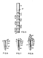
- the contour can be better noted in Figure 5 where the contour is shown without the presence of the grooves or flutes.
- the peripheral contour is such to provide a plurality of inwardly tapered sections 30 interspaced by annular bands 32.
- These ledges 34 are annular and are uniformally spaced apart along the entire axial length of the pin 10.
- the upper end 36 as shown in Figure 5 shows the initial cylindrical pin portion prior to its being flattened and angularly bent into the tang shown on Figure 1.
- the depth of the grooves is such that the depth of the larger grooves 26 is greater than the radial width of the annular shelf or ledge 34.
- the depth of the shallower grooves 28 is less than the radial width of the annular shelf or ledge 34.
- the larger grooves or flutes 26 extend entirely around the periphery along both the wider bands 32 as well as across the tapering sections 30.
- the depth of the shallower grooves 28 is less than the radial length of the annular ledge so that it tends to fade or disappear along the tapering portion 30.
- the edge of the shallow groove 28 terminates at a point 38 somewhere along the length of the tapered section 30.
- the presence of the shelves or ledges 34 are significant in improving the torque resistance to dislocation of the pin within the cement prepared bore.
- the ledges provide for deep axial lengths of cement sections which are provided as blocks around the periphery of the post to further secure it in place. Tests on the post of the present invention have shown a substantial increase in retention strength of the post within the cement prepared bore.
- a tooth stub 40 within the gum area 42 where the upper end of the tooth has been broken.
- the tooth has been initially cut down, typically to provide a suitable upper surface 44.
- a retaining member such as the dental post of the present invention.
- the upper end tang 16 of the post 10 extends upwardly above the surface 44 of the tooth stub.
- a superstructure 52 can then be suitably formed onto the tooth stub in accordance with standard well known techniques in the dental line. The superstructure 52 is retained onto the upper end 16 of the dental post 10 and remains securely in place thereby.
Landscapes
- Health & Medical Sciences (AREA)
- Oral & Maxillofacial Surgery (AREA)
- Dentistry (AREA)
- Epidemiology (AREA)
- Life Sciences & Earth Sciences (AREA)
- Animal Behavior & Ethology (AREA)
- General Health & Medical Sciences (AREA)
- Public Health (AREA)
- Veterinary Medicine (AREA)
- Dental Tools And Instruments Or Auxiliary Dental Instruments (AREA)
- Dental Prosthetics (AREA)
Claims (18)
- Zahnwurzelstift zur sicheren Verankerung eines Zahnersatzstückes (52) auf einem präparierten Zahnstumpf (40), mit einem länglichen, zylindrischen Stift (12) zur Befestigung innerhalb des Zahnstumpfes, wobei der zylindrische Stift eine Längsachse und mehrere in Längsrichtung abgeschrägte Abschnitte (30) aufweist, die entlang der Achse angeordnet sind, und mit schraubenartigen Nuten (24), die um den Umfang des Stiftes (12) zu dessen Halterung angeordnet sind, wobei der Stift (12) innerhalb einer mit Zement (50) präparierten Bohrung (48) in einem Zahnstumpf (40) befestigt ist, dadurch gekennzeichnet,
daß jeder der Abschnitte in Richtung eines Aufnahmeendes (14) des Stiftes in dem Zahnstumpf abgeschrägt ist und eine ringförmige, sich radial erstreckende Schulter (34) umfaßt, die jeden abgeschrägten Abschnitt von dem daran anschließenden abgeschrägten Abschnitt trennt, um den Stift (12) innerhalb eines eine Bohrung in dem Zahnstumpf (40) füllenden Zementes zu verankern. - Zahnwurzelstift nach Anspruch 1, gekennzeichnet durch schraubenartige Nuten (24, 26, 28), die um den Umfang des Stiftes (12) zur weiteren Verankerung des Stiftes innerhalb des Zahnstumpfes angeordnet sind und durch abgeschrägte Abschnitte, die ringförmige Rinnen (34) an den Schultern aufweisen.
- Zahnwurzelstift nach Anspruch 2, dadurch gekennzeichnet,
daß die ringförmigen Rinnen längs des Stiftes (12) gleichförmig voneinander beabstandet angeordnet sind. - Zahnwurzelstift nach Anspruch 2, dadurch gekennzeichnet,
daß jeder der abgeschrägten Abschnitte (30) an seinem oberen Ende einen zylindrischen Abschnitt aufweist (32), der in der Schulter endet. - Zahnwurzelstift nach Anspruch 4, dadurch gekennzeichnet,
daß der zylindrische Abschnitt (32) jedes abgeschrägten Abschnittes (30) der äußeren Umfangskante des Stiftes (12) entspricht. - Zahnwurzelstift nach Anspruch 5, dadurch gekennzeichnet,
daß wenigstens einige der schraubenartigen Nuten (24, 26, 28) die zylindrischen Abschnitte (32) durchdringen. - Zahnwurzelstift nach Anspruch 2, dadurch gekennzeichnet,
daß wenigstens einige der schraubenartigen Nuten (24, 26, 28) längs der abgeschrägten Abschnitte (30) schwinden. - Zahnwurzelstift nach Anspruch 2, dadurch gekennzeichnet,
daß wenigstens einige der schraubenartigen Nuten (24, 28) geringere Tiefe aufweisen als die Tiefe der ringförmigen Rinnen (34). - Zahnwurzelstift nach Anspruch 2, dadurch gekennzeichnet,
daß die schraubenartigen Nuten eine erste Gruppe Nuten (24, 26) mit einer geringeren Tiefe als die Tiefe der ringförmigen Rinnen (34) ausbilden und eine zweite Gruppe von Nuten (24, 28), die in Folge mit der ersten Gruppe Nuten (24, 26) abwechseln und eine geringere Tiefe aufweisen, als die Tiefe der ringförmigen Rinnen (34). - Zahnwurzelstift nach Anspruch 2, gekennzeichnet durch ein Kopfteil (16, 36), das sich derart von dem Stift (12) erstreckt, daß es nach außen aus dem Zahnstumpf (40), auf dem das Zahnersatzstück befestigt werden kann, wenn der Stift (12) in die Bohrung des Zahnstumpfes (48) eingeführt ist, herausragt.
- Zahnwurzelstift nach Anspruch 10, dadurch gekennzeichnet,
daß das Kopfteil (16, 36) eine mit dem Stift (12) integral ausgebildete abgeplattete Bohrerangel (16) aufweist. - Zahnwurzelstift nach Anspruch 11, dadurch gekennzeichnet,
daß die Bohrerangel (16) unter einem Winkel in Bezug auf die Achse des Stiftes (12) ausgerichtet ist. - Zahnwurzelstift nach Anspruch 1, dadurch gekennzeichnet,
daß der Stift (12) an seinem Aufnahmeende einen unteren Endabschnitt (14) aufweist, dessen Durchmesser im wesentlichen gleich dem Außenumfangsdurchmesser des Stiftes (12) ist. - Verfahren zur Ausbildung eines Zahnwurzelstiftes zur Befestigung einer dentalen prothetischen Einrichtung (52) auf einem präparierten Zahnstumpf (40), gekennzeichnet durch die Schritte:
Auswalzen mehrerer sich in Längsrichtung erstreckender abgeschrägter Abschnitte (30) in Richtung eines Aufnahmeendes längs der Oberfläche eines Stiftes (12) und
Ausbilden von schraubenartigen Nuten (24, 26, 28) um den Umfang des Stiftes. - Verfahren nach Anspruch 14, dadurch gekennzeichnet,
daß der Schritt des Ausbildens das Auswalzen der schraubenartigen Nuten (24, 26, 28) umfaßt. - Verfahren nach Anspruch 15, dadurch gekennzeichnet,
daß die schraubenartigen Nuten (24, 26, 28) und die abgeschrägten Abschnitte (30) zusammen in einem einzigen Auswalzvorgang ausgebildet werden. - Verfahren nach Anspruch 16, dadurch gekennzeichnet,
daß die axiale Länge des Stiftes (12) während des Auswalzvorganges verlängert wird. - Verfahren nach Anspruch 16, dadurch gekennzeichnet,
daß die abgeschrägten Abschnitte (30) in Längsrichtung voneinander beabstandete, im wesentlichen radiale Ränder (34) entlang der Länge des Stiftes (12) ausbilden.
Applications Claiming Priority (2)
| Application Number | Priority Date | Filing Date | Title |
|---|---|---|---|
| US904205 | 1986-09-08 | ||
| US06/904,205 US4729736A (en) | 1986-09-08 | 1986-09-08 | Contoured dental posts |
Publications (2)
| Publication Number | Publication Date |
|---|---|
| EP0260446A1 EP0260446A1 (de) | 1988-03-23 |
| EP0260446B1 true EP0260446B1 (de) | 1992-03-04 |
Family
ID=25418767
Family Applications (1)
| Application Number | Title | Priority Date | Filing Date |
|---|---|---|---|
| EP87111821A Expired - Lifetime EP0260446B1 (de) | 1986-09-08 | 1987-08-14 | Geformter Zahnwurzelstift |
Country Status (6)
| Country | Link |
|---|---|
| US (1) | US4729736A (de) |
| EP (1) | EP0260446B1 (de) |
| JP (1) | JPH0817784B2 (de) |
| CA (1) | CA1279510C (de) |
| DE (1) | DE3777035D1 (de) |
| ES (1) | ES2030025T3 (de) |
Cited By (1)
| Publication number | Priority date | Publication date | Assignee | Title |
|---|---|---|---|---|
| US9089384B1 (en) | 2013-05-21 | 2015-07-28 | Austin H. Sampson | Dental pin system |
Families Citing this family (18)
| Publication number | Priority date | Publication date | Assignee | Title |
|---|---|---|---|---|
| US4932870A (en) * | 1988-08-18 | 1990-06-12 | Ipco Corporation | Dental post and method for making the same |
| GB8826823D0 (en) * | 1988-11-16 | 1988-12-21 | Filhol Stuart J | Dental equipment & method |
| AU4463689A (en) * | 1988-11-16 | 1990-05-24 | Stuart Julian Filhol | Dental equipment and method |
| US4990090A (en) * | 1988-11-18 | 1991-02-05 | Roane James B | Endodontic post construction |
| US5145373A (en) * | 1989-02-09 | 1992-09-08 | Roane James B | Endodontic post |
| US5035620A (en) * | 1989-02-09 | 1991-07-30 | Roane James B | Endodontic post with spiral groove |
| GB9122295D0 (en) * | 1991-10-21 | 1991-12-04 | Filhol Stuart J | Dental pin assembly |
| US5284443A (en) * | 1992-08-28 | 1994-02-08 | Coltene/Whaledent, Inc. | Method of forming dental restorations |
| US5275563A (en) * | 1992-09-02 | 1994-01-04 | Essential Dental Systems, Inc. | Dental post extracting drill |
| US5820375A (en) * | 1996-07-16 | 1998-10-13 | Wellesley Research Associates, Inc. | Dental post having cutting and non-cutting surfaces |
| US6186791B1 (en) | 1998-08-11 | 2001-02-13 | Jeneric/Pentron Incorporated | Fiber reinforced composite post |
| US7488175B2 (en) * | 1998-08-11 | 2009-02-10 | Pentron Clinical Technologies, Llc | Fiber reinforced composite post |
| JP3675259B2 (ja) * | 1999-11-12 | 2005-07-27 | 愛知製鋼株式会社 | 義歯アタッチメント用のキーパ |
| WO2005087132A1 (es) * | 2004-02-19 | 2005-09-22 | Enrique Kogan Frenk | Poste intra radicular para reconstrucción de dientes con tratamiento de conductos |
| DE102005021807B3 (de) * | 2005-05-04 | 2006-11-30 | Universität Rostock | Isoelastischer Endodontiestift |
| DK2281524T3 (da) | 2009-08-05 | 2013-02-11 | Peter E Nordin | Tandstolpe |
| DOP2015000272A (es) * | 2015-11-05 | 2017-05-31 | Edgardo Feliz Matos Leandro | Perno intrarradicular ancla |
| TWM549054U (zh) * | 2017-06-05 | 2017-09-21 | Chung-Chih Tseng | 贋復補綴復型裝置 |
Family Cites Families (9)
| Publication number | Priority date | Publication date | Assignee | Title |
|---|---|---|---|---|
| US313737A (en) * | 1885-03-10 | Artificial | ||
| US2536669A (en) * | 1947-07-29 | 1951-01-02 | Thau-Jensen Orla | Root pin for use in reinforcement in lays, cast crowns, and pivot teeth |
| FR2063993B1 (de) * | 1969-10-22 | 1975-11-07 | Scialom Jacques | |
| FR2395738A1 (fr) * | 1977-07-01 | 1979-01-26 | Bouet Bernard | Prisonnier amovible a l'usage notamment d'implant dentaire |
| US4268253A (en) * | 1979-12-26 | 1981-05-19 | Gross Michael J | Dowel post for dental and medical prosthetic devices |
| US4293302A (en) * | 1980-03-26 | 1981-10-06 | Scientific Advances, Inc. | Tooth implants |
| GB2117641B (en) * | 1982-03-24 | 1985-03-27 | Winter Moore Peter Howard | Dental post assembly |
| US4571187A (en) * | 1983-04-29 | 1986-02-18 | Ipco Corporation | Dental post for retention of a prosthetic superstructure |
| US4479783A (en) * | 1983-04-29 | 1984-10-30 | Ipco Corporation | Helically fluted dental post |
-
1986
- 1986-09-08 US US06/904,205 patent/US4729736A/en not_active Expired - Lifetime
-
1987
- 1987-08-14 ES ES198787111821T patent/ES2030025T3/es not_active Expired - Lifetime
- 1987-08-14 DE DE8787111821T patent/DE3777035D1/de not_active Expired - Lifetime
- 1987-08-14 EP EP87111821A patent/EP0260446B1/de not_active Expired - Lifetime
- 1987-09-04 CA CA000546241A patent/CA1279510C/en not_active Expired - Lifetime
- 1987-09-08 JP JP62223197A patent/JPH0817784B2/ja not_active Expired - Fee Related
Cited By (1)
| Publication number | Priority date | Publication date | Assignee | Title |
|---|---|---|---|---|
| US9089384B1 (en) | 2013-05-21 | 2015-07-28 | Austin H. Sampson | Dental pin system |
Also Published As
| Publication number | Publication date |
|---|---|
| EP0260446A1 (de) | 1988-03-23 |
| CA1279510C (en) | 1991-01-29 |
| US4729736A (en) | 1988-03-08 |
| DE3777035D1 (de) | 1992-04-09 |
| JPH0817784B2 (ja) | 1996-02-28 |
| JPS63153058A (ja) | 1988-06-25 |
| ES2030025T3 (es) | 1992-10-16 |
Similar Documents
| Publication | Publication Date | Title |
|---|---|---|
| EP0260446B1 (de) | Geformter Zahnwurzelstift | |
| EP0536386B1 (de) | Dentalstift mit intermittierendem gewinde | |
| US4917606A (en) | Threaded dental anchor | |
| US6386877B1 (en) | Implant for holding and/or forming a dental prosthesis or artificial finger joint | |
| EP2662052B1 (de) | Zahnimplantat und Kit mit dem Zahnimplantat | |
| US6315564B1 (en) | Bone implant | |
| US4767332A (en) | Threaded dental anchor | |
| US4479783A (en) | Helically fluted dental post | |
| JP2016503666A (ja) | 凝縮インプラント | |
| US4268253A (en) | Dowel post for dental and medical prosthetic devices | |
| US5145373A (en) | Endodontic post | |
| EP0806916B1 (de) | Gesplitzter gewindebohrer und lentulo-bohrer für zahnwurzelstift-system | |
| EP0455727A4 (en) | Dental anchor and drill for use therewith | |
| US4408990A (en) | Endodontic dental implant | |
| AU4220489A (en) | Dental post and method for making the same | |
| US5035620A (en) | Endodontic post with spiral groove | |
| US6406296B1 (en) | Implant with enlarged proximal segment | |
| EP0026246B1 (de) | Stift zur Verankerung einer zahnärztlichen oder medizinischen prothetischen Vorrichtung | |
| WO1999060945A1 (en) | Assembly of drills for forming a hole in a tooth root and method for placing a canal post in a tooth root | |
| CA1251065A (en) | Threaded dental anchor |
Legal Events
| Date | Code | Title | Description |
|---|---|---|---|
| PUAI | Public reference made under article 153(3) epc to a published international application that has entered the european phase |
Free format text: ORIGINAL CODE: 0009012 |
|
| AK | Designated contracting states |
Kind code of ref document: A1 Designated state(s): CH DE ES FR GB IT LI SE |
|
| 17P | Request for examination filed |
Effective date: 19880921 |
|
| 17Q | First examination report despatched |
Effective date: 19900130 |
|
| GRAA | (expected) grant |
Free format text: ORIGINAL CODE: 0009210 |
|
| RAP1 | Party data changed (applicant data changed or rights of an application transferred) |
Owner name: COLTENE/WHALEDENT, INC. |
|
| AK | Designated contracting states |
Kind code of ref document: B1 Designated state(s): CH DE ES FR GB IT LI SE |
|
| PG25 | Lapsed in a contracting state [announced via postgrant information from national office to epo] |
Ref country code: FR Effective date: 19920304 Ref country code: CH Effective date: 19920304 Ref country code: LI Effective date: 19920304 |
|
| REF | Corresponds to: |
Ref document number: 3777035 Country of ref document: DE Date of ref document: 19920409 |
|
| ITF | It: translation for a ep patent filed | ||
| REG | Reference to a national code |
Ref country code: CH Ref legal event code: PL |
|
| EN | Fr: translation not filed | ||
| REG | Reference to a national code |
Ref country code: ES Ref legal event code: FG2A Ref document number: 2030025 Country of ref document: ES Kind code of ref document: T3 |
|
| PLBE | No opposition filed within time limit |
Free format text: ORIGINAL CODE: 0009261 |
|
| STAA | Information on the status of an ep patent application or granted ep patent |
Free format text: STATUS: NO OPPOSITION FILED WITHIN TIME LIMIT |
|
| 26N | No opposition filed | ||
| EAL | Se: european patent in force in sweden |
Ref document number: 87111821.2 |
|
| REG | Reference to a national code |
Ref country code: GB Ref legal event code: IF02 |
|
| PGFP | Annual fee paid to national office [announced via postgrant information from national office to epo] |
Ref country code: ES Payment date: 20050826 Year of fee payment: 19 |
|
| PGFP | Annual fee paid to national office [announced via postgrant information from national office to epo] |
Ref country code: GB Payment date: 20060825 Year of fee payment: 20 |
|
| PGFP | Annual fee paid to national office [announced via postgrant information from national office to epo] |
Ref country code: IT Payment date: 20060831 Year of fee payment: 20 |
|
| PGFP | Annual fee paid to national office [announced via postgrant information from national office to epo] |
Ref country code: DE Payment date: 20061002 Year of fee payment: 20 |
|
| REG | Reference to a national code |
Ref country code: GB Ref legal event code: PE20 |
|
| EUG | Se: european patent has lapsed | ||
| REG | Reference to a national code |
Ref country code: ES Ref legal event code: FD2A Effective date: 20070816 |
|
| PG25 | Lapsed in a contracting state [announced via postgrant information from national office to epo] |
Ref country code: GB Free format text: LAPSE BECAUSE OF EXPIRATION OF PROTECTION Effective date: 20070813 |
|
| PG25 | Lapsed in a contracting state [announced via postgrant information from national office to epo] |
Ref country code: ES Free format text: LAPSE BECAUSE OF EXPIRATION OF PROTECTION Effective date: 20070816 |
|
| PGFP | Annual fee paid to national office [announced via postgrant information from national office to epo] |
Ref country code: SE Payment date: 20060829 Year of fee payment: 20 |