EP0260464B1 - Pompe de dosage - Google Patents
Pompe de dosage Download PDFInfo
- Publication number
- EP0260464B1 EP0260464B1 EP87111972A EP87111972A EP0260464B1 EP 0260464 B1 EP0260464 B1 EP 0260464B1 EP 87111972 A EP87111972 A EP 87111972A EP 87111972 A EP87111972 A EP 87111972A EP 0260464 B1 EP0260464 B1 EP 0260464B1
- Authority
- EP
- European Patent Office
- Prior art keywords
- membrane
- pump
- valve
- dosing
- metering
- Prior art date
- Legal status (The legal status is an assumption and is not a legal conclusion. Google has not performed a legal analysis and makes no representation as to the accuracy of the status listed.)
- Expired - Lifetime
Links
- 239000012528 membrane Substances 0.000 claims description 23
- 230000000630 rising effect Effects 0.000 claims 2
- 230000000694 effects Effects 0.000 claims 1
- 238000009423 ventilation Methods 0.000 abstract description 2
- 230000000740 bleeding effect Effects 0.000 abstract 1
- 230000006835 compression Effects 0.000 description 5
- 238000007906 compression Methods 0.000 description 5
- 239000007789 gas Substances 0.000 description 4
- 239000007788 liquid Substances 0.000 description 2
- 238000013022 venting Methods 0.000 description 2
- 238000011161 development Methods 0.000 description 1
- 230000018109 developmental process Effects 0.000 description 1
- 230000005284 excitation Effects 0.000 description 1
- 230000001771 impaired effect Effects 0.000 description 1
- 238000005086 pumping Methods 0.000 description 1
Images


Classifications
-
- F—MECHANICAL ENGINEERING; LIGHTING; HEATING; WEAPONS; BLASTING
- F04—POSITIVE - DISPLACEMENT MACHINES FOR LIQUIDS; PUMPS FOR LIQUIDS OR ELASTIC FLUIDS
- F04B—POSITIVE-DISPLACEMENT MACHINES FOR LIQUIDS; PUMPS
- F04B43/00—Machines, pumps, or pumping installations having flexible working members
- F04B43/02—Machines, pumps, or pumping installations having flexible working members having plate-like flexible members, e.g. diaphragms
-
- F—MECHANICAL ENGINEERING; LIGHTING; HEATING; WEAPONS; BLASTING
- F04—POSITIVE - DISPLACEMENT MACHINES FOR LIQUIDS; PUMPS FOR LIQUIDS OR ELASTIC FLUIDS
- F04B—POSITIVE-DISPLACEMENT MACHINES FOR LIQUIDS; PUMPS
- F04B23/00—Pumping installations or systems
- F04B23/04—Combinations of two or more pumps
- F04B23/06—Combinations of two or more pumps the pumps being all of reciprocating positive-displacement type
-
- F—MECHANICAL ENGINEERING; LIGHTING; HEATING; WEAPONS; BLASTING
- F04—POSITIVE - DISPLACEMENT MACHINES FOR LIQUIDS; PUMPS FOR LIQUIDS OR ELASTIC FLUIDS
- F04B—POSITIVE-DISPLACEMENT MACHINES FOR LIQUIDS; PUMPS
- F04B43/00—Machines, pumps, or pumping installations having flexible working members
- F04B43/0009—Special features
- F04B43/0045—Special features with a number of independent working chambers which are actuated successively by one mechanism
-
- F—MECHANICAL ENGINEERING; LIGHTING; HEATING; WEAPONS; BLASTING
- F04—POSITIVE - DISPLACEMENT MACHINES FOR LIQUIDS; PUMPS FOR LIQUIDS OR ELASTIC FLUIDS
- F04B—POSITIVE-DISPLACEMENT MACHINES FOR LIQUIDS; PUMPS
- F04B53/00—Component parts, details or accessories not provided for in, or of interest apart from, groups F04B1/00 - F04B23/00 or F04B39/00 - F04B47/00
- F04B53/06—Venting
Definitions
- the invention relates to a metering pump according to the first part of patent claim 1.
- Such a metering pump is known from DE-A 2 803 470.
- the vent valve arranged in the return line in this known metering pump is designed as a liquid throttle valve which practically only lets gases through and prevents the passage of liquids. The gases from the pump chamber can thus be conveyed back from the pump chamber into the dosing agent container during the pressure stroke. However, it cannot be prevented that gas also reaches the metering point during the pressure stroke.
- a metering pump is known in which the diaphragm pump acts as a pre-feed pump.
- a piston pump with the necessary piston seals is provided as a metering pump.
- the piston seals have a limited lifespan when dosing aggressive media, so that such pumps are not suitable for dosing aggressive media.
- the object of the invention is to provide a metering pump of the type described above, which is self-priming and self-venting.
- the metering pump 1 has a pump head 2. This has a pump chamber 3 extending in the vertical direction. At the lower end of the pumping chamber, seen in the vertical direction, there is a suction channel 4, which is connected to a suction line 6 via a suction valve 5. The suction line 6 leads into a dosing agent container 7.
- a riser 8 opens.
- the upper end of the riser as seen in the vertical direction leads via a pressure valve 9 to a connection 10 that can be connected to a metering point.
- a metering membrane 11 is clamped in the pump chamber in the manner shown in FIG.
- the plunger has a stop 13. Between this and a fixed frame plate 14, a compression spring 15 is provided, which biases the membrane 11 in the suction position.
- a shaft 18 is supported which carries a metering eccentric 19.
- the end 16 of the plunger is biased against the metering eccentric 19 by the compression spring 15.
- a transverse bore 20 opens as directly as possible at the upper end of the riser 8, that is to say directly in front of the pressure valve 9. This leads into the valve chamber 21 of a ventilation valve formed by a diaphragm pump 22. At the end of the transverse bore 20, a valve seat 23 is incorporated. In the upper region of the valve chamber 21, seen in the vertical direction, there is a riser pipe 23, which is connected to a return line 25 via a pressure valve 24. In the exemplary embodiment shown, this leads back into the dosing agent container 7.
- the membrane is firmly connected to a tappet 26 on its side facing away from the valve chamber. Between the back of the membrane and a wall part 27 of the housing, a compression spring 28 is provided, which is biased so that the membrane is initially held in the closed position shown in FIG. 1.
- the end of the plunger facing away from the membrane is adjustably connected to a yoke 29 by a lock nut 30.
- a second eccentric 31 sits on the shaft 18.
- the two eccentrics are fixedly connected to a toothed wheel 32, which is drivingly connected to a pinion 33 of a drive motor 34.
- the second eccentric 31 is designed such that the plunger 26 is moved in the desired angular range such that the diaphragm 35 of the diaphragm pump executes a suction stroke against the compression spring 28.
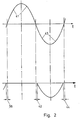
- the two eccentrics 19 and 31 are so angularly offset from one another that the cycle shown in FIG. 2 takes place.
- the valve formed by the diaphragm pump 22 closes a small time period 36 before the pressure stroke of the metering diaphragm 11 is carried out.
- the vent valve formed by the diaphragm pump opens a small time period 42 after the metering stroke has ended. During this period, the suction stroke 43 of the membrane 11 has already started.
- the vent valve closes by placing the membrane 35 in the position shown in FIG. 1 a short time period 44 before the end of the suction stroke. This ensures that no gas can enter the system during the pressure stroke.
- the locking spring 28 can be designed in such a way that it yields at a certain pressure in the pump head, so that the vent valve also acts as a pressure relief valve.
- FIG. 3 initially has all the features shown in FIG. 1.
- a check valve 38 is provided by the vent valve formed by the diaphragm pump 22. This accelerates the venting.
- the plunger 26 is not pulled back into the suction position by the motor 34 but by a separately controlled lifting magnet 39.
- the excitation of the solenoid 39 is controlled by a controller 40.
- a sensor 45 is provided which detects the rotational position of the metering eccentric 19 and delivers an output signal to the controller 40 via this rotary position in order to ensure the synchronization of the metering stroke of the membrane 35 with the membrane 11 in the manner described above.
- the controller 40 is designed in such a way that the membrane 35 does not follow each stroke of the membrane 11, but remains a predetermined number of working cycles of the membrane 11 in the closed position shown in FIG. It is thereby achieved that the diaphragm 35 is used much less without the pump performance of the pump as a whole being impaired.
- the controller 40 can be set so that the number of skipped strokes through the membrane 35 is adjustable depending on the medium to be conveyed and its tendency to outgas.
Landscapes
- Engineering & Computer Science (AREA)
- Mechanical Engineering (AREA)
- General Engineering & Computer Science (AREA)
- Reciprocating Pumps (AREA)
- Details Of Reciprocating Pumps (AREA)
- Feeding, Discharge, Calcimining, Fusing, And Gas-Generation Devices (AREA)
Claims (9)
Priority Applications (1)
| Application Number | Priority Date | Filing Date | Title |
|---|---|---|---|
| AT87111972T ATE50321T1 (de) | 1986-09-19 | 1987-08-18 | Dosierpumpe. |
Applications Claiming Priority (2)
| Application Number | Priority Date | Filing Date | Title |
|---|---|---|---|
| DE3631984A DE3631984C1 (de) | 1986-09-19 | 1986-09-19 | Dosierpumpe |
| DE3631984 | 1986-09-19 |
Publications (2)
| Publication Number | Publication Date |
|---|---|
| EP0260464A1 EP0260464A1 (fr) | 1988-03-23 |
| EP0260464B1 true EP0260464B1 (fr) | 1990-02-07 |
Family
ID=6309976
Family Applications (1)
| Application Number | Title | Priority Date | Filing Date |
|---|---|---|---|
| EP87111972A Expired - Lifetime EP0260464B1 (fr) | 1986-09-19 | 1987-08-18 | Pompe de dosage |
Country Status (5)
| Country | Link |
|---|---|
| US (1) | US4865525A (fr) |
| EP (1) | EP0260464B1 (fr) |
| JP (1) | JPS6388283A (fr) |
| AT (1) | ATE50321T1 (fr) |
| DE (1) | DE3631984C1 (fr) |
Families Citing this family (42)
| Publication number | Priority date | Publication date | Assignee | Title |
|---|---|---|---|---|
| DE3827489C1 (fr) * | 1988-08-12 | 1989-10-12 | Gruenbeck Wasseraufbereitung Gmbh, 8884 Hoechstaedt, De | |
| GB9023552D0 (en) * | 1990-10-30 | 1990-12-12 | Domino Printing Sciences Plc | A two-stage pump for a continuous ink jet printer |
| DE9109288U1 (de) * | 1991-07-27 | 1992-09-03 | Verpaco AG, Hünenberg | Mehrfach-Dosierstation zum aseptischen Abfüllen von Produkten |
| DE4219663C2 (de) * | 1992-06-16 | 1996-01-18 | Prominent Dosiertechnik Gmbh | Flüssigkeits-Dosierpumpe |
| DE4241030C1 (de) * | 1992-12-05 | 1994-06-01 | Lang Apparatebau Gmbh | Dosierpumpe mit Entlüftungsventil |
| US5354183A (en) * | 1993-02-11 | 1994-10-11 | Elasis Sistema Ricerca Fiat Nel Mezzogiorno Societa Consortile Per Azioni | Pumping device with a main pumping stage and a supply pump |
| US5407424A (en) * | 1993-02-24 | 1995-04-18 | Scimed Life Systems, Inc. | Angioplasty perfusion pump |
| DE4439962A1 (de) * | 1994-11-09 | 1996-05-15 | Lang Apparatebau Gmbh | Dosierpumpe mit Entlüftungseinrichtung |
| JP3601148B2 (ja) * | 1994-12-26 | 2004-12-15 | アイシン精機株式会社 | ベローズポンプ |
| DE19712096C1 (de) * | 1997-03-22 | 1998-04-02 | Lang Apparatebau Gmbh | Dosierpumpe zum dosierten Fördern von Flüssigkeiten |
| US8172546B2 (en) | 1998-11-23 | 2012-05-08 | Entegris, Inc. | System and method for correcting for pressure variations using a motor |
| US7029238B1 (en) * | 1998-11-23 | 2006-04-18 | Mykrolis Corporation | Pump controller for precision pumping apparatus |
| US6325932B1 (en) * | 1999-11-30 | 2001-12-04 | Mykrolis Corporation | Apparatus and method for pumping high viscosity fluid |
| ATE446800T1 (de) | 2000-05-12 | 2009-11-15 | Pall Corp | Filter |
| DE60117260T2 (de) | 2000-05-12 | 2006-10-05 | Pall Corp. | Filtrationssysteme |
| JP3718118B2 (ja) * | 2000-10-05 | 2005-11-16 | 株式会社コガネイ | 液体吐出装置および液体吐出方法 |
| JP3890229B2 (ja) * | 2001-12-27 | 2007-03-07 | 株式会社コガネイ | 薬液供給装置および薬液供給装置の脱気方法 |
| JP3947398B2 (ja) * | 2001-12-28 | 2007-07-18 | 株式会社コガネイ | 薬液供給装置および薬液供給方法 |
| JP2005076534A (ja) * | 2003-08-29 | 2005-03-24 | Mitsumi Electric Co Ltd | 排気弁装置付小型ポンプ及びその排気弁装置付小型ポンプを使用した血圧計 |
| US11319944B2 (en) * | 2003-10-30 | 2022-05-03 | Deka Products Limited Partnership | Disposable interconnected pump cassettes having first and second pump chambers with valved inlet and outlet connections |
| PL1791579T3 (pl) * | 2004-09-20 | 2009-10-30 | Medela Holding Ag | Pompa membranowa z zaworem odpowietrzającym |
| US8292598B2 (en) | 2004-11-23 | 2012-10-23 | Entegris, Inc. | System and method for a variable home position dispense system |
| US8753097B2 (en) | 2005-11-21 | 2014-06-17 | Entegris, Inc. | Method and system for high viscosity pump |
| KR101308784B1 (ko) | 2005-11-21 | 2013-09-17 | 엔테그리스, 아이엔씨. | 소형 폼 팩터를 갖는 펌프용 시스템 및 방법 |
| US20070128061A1 (en) * | 2005-12-02 | 2007-06-07 | Iraj Gashgaee | Fixed volume valve system |
| US8083498B2 (en) | 2005-12-02 | 2011-12-27 | Entegris, Inc. | System and method for position control of a mechanical piston in a pump |
| US8025486B2 (en) | 2005-12-02 | 2011-09-27 | Entegris, Inc. | System and method for valve sequencing in a pump |
| EP1958039B9 (fr) | 2005-12-02 | 2011-09-07 | Entegris, Inc. | Systemes d'entree/sortie, procedes et dispositifs pour assurer l'interface avec un controleur de pompe |
| US7850431B2 (en) | 2005-12-02 | 2010-12-14 | Entegris, Inc. | System and method for control of fluid pressure |
| US7878765B2 (en) | 2005-12-02 | 2011-02-01 | Entegris, Inc. | System and method for monitoring operation of a pump |
| JP5302002B2 (ja) * | 2005-12-02 | 2013-10-02 | インテグリス・インコーポレーテッド | Oリング無し薄型取付部品および取付部品アセンブリ |
| KR101243509B1 (ko) | 2005-12-02 | 2013-03-20 | 엔테그리스, 아이엔씨. | 펌프에서의 압력 보상을 위한 시스템 및 방법 |
| JP5345853B2 (ja) * | 2005-12-05 | 2013-11-20 | インテグリス・インコーポレーテッド | ポンプのための誤差容積システムおよび方法 |
| TWI402423B (zh) | 2006-02-28 | 2013-07-21 | Entegris Inc | 用於一幫浦操作之系統及方法 |
| US7494265B2 (en) | 2006-03-01 | 2009-02-24 | Entegris, Inc. | System and method for controlled mixing of fluids via temperature |
| US7684446B2 (en) * | 2006-03-01 | 2010-03-23 | Entegris, Inc. | System and method for multiplexing setpoints |
| US20140056724A1 (en) * | 2012-08-27 | 2014-02-27 | Hamilton Sundstrand Corporation | Diaphragm metering pump having a degassing system |
| US10876527B2 (en) * | 2015-06-22 | 2020-12-29 | Seko S.P.A. | Bleed valve and self-bleeding pump provided with such valve |
| JP6177850B2 (ja) * | 2015-09-17 | 2017-08-09 | 株式会社オーヤラックス | ポンプ装置 |
| JP6892982B2 (ja) * | 2017-02-03 | 2021-06-23 | 応研精工株式会社 | ダイヤフラムポンプ |
| DE102018133214A1 (de) * | 2018-12-20 | 2020-06-25 | Lutz-Jesco Gmbh | Dosierpumpe mit integriertem Überströmventil und Ventileinsatz für eine Dosierpumpe |
| LT4095224T (lt) * | 2021-05-26 | 2024-10-10 | Lanxess Deutschland Gmbh | Gėrimų konservavimo su siurblio vėdinimu būdas ir įrenginys |
Family Cites Families (9)
| Publication number | Priority date | Publication date | Assignee | Title |
|---|---|---|---|---|
| US1931691A (en) * | 1930-04-28 | 1933-10-24 | Campbell Wyant & Cannon Co | Fuel pump for oil engines |
| US2308974A (en) * | 1939-11-01 | 1943-01-19 | Lyndus E Harper | Positive displacement pump |
| CH457146A (de) * | 1967-11-20 | 1968-05-31 | Glutz Blotzheim Nachfolger Ag | Elektromagnetische Schwingankerpumpe |
| US3680985A (en) * | 1970-12-28 | 1972-08-01 | Mec O Matic The | Pump |
| DE2651614C2 (de) * | 1976-11-12 | 1984-10-04 | Lang Apparatebau GmbH, 8227 Siegsdorf | Dosierpumpe |
| DE2803470B2 (de) * | 1978-01-27 | 1980-06-04 | Dulger, Viktor, 6900 Heidelberg | Entlüftungsvorrichtung fur eine Flussigkeitskolbenpumpe, insbesondere Dosierpumpe |
| US4236881A (en) * | 1978-05-03 | 1980-12-02 | Ecodyne Corporation | Liquid metering pump |
| US4278406A (en) * | 1979-11-07 | 1981-07-14 | R. W. Beckett Corporation | Electromagnetic pump |
| JPS6128073U (ja) * | 1984-07-25 | 1986-02-19 | 昭和電線電纜株式会社 | 試験装置 |
-
1986
- 1986-09-19 DE DE3631984A patent/DE3631984C1/de not_active Expired
-
1987
- 1987-08-18 AT AT87111972T patent/ATE50321T1/de not_active IP Right Cessation
- 1987-08-18 EP EP87111972A patent/EP0260464B1/fr not_active Expired - Lifetime
- 1987-08-25 US US07/089,226 patent/US4865525A/en not_active Expired - Fee Related
- 1987-09-19 JP JP62233759A patent/JPS6388283A/ja active Pending
Also Published As
| Publication number | Publication date |
|---|---|
| JPS6388283A (ja) | 1988-04-19 |
| US4865525A (en) | 1989-09-12 |
| DE3631984C1 (de) | 1987-12-17 |
| ATE50321T1 (de) | 1990-02-15 |
| EP0260464A1 (fr) | 1988-03-23 |
Similar Documents
| Publication | Publication Date | Title |
|---|---|---|
| EP0260464B1 (fr) | Pompe de dosage | |
| EP0354484B1 (fr) | Pompe doseuse | |
| EP0791138B1 (fr) | Pompe de dosage a systeme de purge | |
| DE3900327A1 (de) | Vorrichtung fuer ein antiblockiersystem | |
| EP0688954A1 (fr) | Dispositif de supplément contrÔlé pour des pompes à membrane et à haute pression | |
| EP0007109B1 (fr) | Appareil pour le dosage d'une solution d'agents chimiques dans un courant de liquide | |
| DE2807514C3 (de) | Membranpumpe | |
| CH181340A (de) | Einrichtung zur mechanischen Einspritzung des Brennstoffes bei Verbrennungsmotoren. | |
| DE3928411C2 (fr) | ||
| EP0316331B1 (fr) | Dispositif d'injection pour l'introduction de carburants dans la chambre de combustion de moteurs a combustion interne | |
| EP0316537B1 (fr) | Pompe doseuse | |
| DE69408390T2 (de) | Brennstoffpumpvorrichtung | |
| EP1658438A1 (fr) | Pompe a liquides | |
| DE3508170A1 (de) | Hydraulische vorrichtung | |
| DE10035537A1 (de) | Kolbenpumpe | |
| DE2600572A1 (de) | Vorrichtung zum dosieren von chemikalienloesungen | |
| DE155340C (fr) | ||
| DE4417213A1 (de) | Vorrichtung zum Befördern eines Flüssigkeitsmittels | |
| DE3003832C2 (de) | Pumpe, insbesondere Membranpumpe | |
| AT363782B (de) | Vorrichtung zum dosieren einer chemikalienloesung in stroemende frischfluessigkeit | |
| EP1146224A1 (fr) | Dispositif d'alimentation en carburant d'un moteur à combustion interne | |
| DE555402C (de) | Halbzwanglaeufige Steuerung fuer Ventile von Kolbenpumpen fuer Homogenisiervorrichtungen | |
| DE2442714A1 (de) | Verfahren und vorrichtung zum pumpen von fluessigkeiten mittels einer membrandosierpumpe | |
| DE3805866A1 (de) | Kraftstoff-foerdersystem | |
| DE2128168C3 (de) | Antiblockierregelsysteme für Fahrzeuge |
Legal Events
| Date | Code | Title | Description |
|---|---|---|---|
| PUAI | Public reference made under article 153(3) epc to a published international application that has entered the european phase |
Free format text: ORIGINAL CODE: 0009012 |
|
| AK | Designated contracting states |
Kind code of ref document: A1 Designated state(s): AT BE CH FR GB IT LI NL |
|
| 17P | Request for examination filed |
Effective date: 19880511 |
|
| 17Q | First examination report despatched |
Effective date: 19880912 |
|
| GRAA | (expected) grant |
Free format text: ORIGINAL CODE: 0009210 |
|
| AK | Designated contracting states |
Kind code of ref document: B1 Designated state(s): AT BE CH FR GB IT LI NL |
|
| REF | Corresponds to: |
Ref document number: 50321 Country of ref document: AT Date of ref document: 19900215 Kind code of ref document: T |
|
| ET | Fr: translation filed | ||
| GBT | Gb: translation of ep patent filed (gb section 77(6)(a)/1977) | ||
| ITF | It: translation for a ep patent filed | ||
| PLBE | No opposition filed within time limit |
Free format text: ORIGINAL CODE: 0009261 |
|
| STAA | Information on the status of an ep patent application or granted ep patent |
Free format text: STATUS: NO OPPOSITION FILED WITHIN TIME LIMIT |
|
| 26N | No opposition filed | ||
| ITTA | It: last paid annual fee | ||
| PGFP | Annual fee paid to national office [announced via postgrant information from national office to epo] |
Ref country code: GB Payment date: 19960802 Year of fee payment: 10 |
|
| PGFP | Annual fee paid to national office [announced via postgrant information from national office to epo] |
Ref country code: FR Payment date: 19960810 Year of fee payment: 10 |
|
| PGFP | Annual fee paid to national office [announced via postgrant information from national office to epo] |
Ref country code: BE Payment date: 19960822 Year of fee payment: 10 Ref country code: AT Payment date: 19960822 Year of fee payment: 10 |
|
| PGFP | Annual fee paid to national office [announced via postgrant information from national office to epo] |
Ref country code: CH Payment date: 19960823 Year of fee payment: 10 |
|
| PGFP | Annual fee paid to national office [announced via postgrant information from national office to epo] |
Ref country code: NL Payment date: 19960828 Year of fee payment: 10 |
|
| PG25 | Lapsed in a contracting state [announced via postgrant information from national office to epo] |
Ref country code: GB Free format text: LAPSE BECAUSE OF NON-PAYMENT OF DUE FEES Effective date: 19970818 Ref country code: AT Free format text: LAPSE BECAUSE OF NON-PAYMENT OF DUE FEES Effective date: 19970818 |
|
| PG25 | Lapsed in a contracting state [announced via postgrant information from national office to epo] |
Ref country code: LI Free format text: LAPSE BECAUSE OF NON-PAYMENT OF DUE FEES Effective date: 19970831 Ref country code: CH Free format text: LAPSE BECAUSE OF NON-PAYMENT OF DUE FEES Effective date: 19970831 Ref country code: BE Free format text: LAPSE BECAUSE OF NON-PAYMENT OF DUE FEES Effective date: 19970831 |
|
| BERE | Be: lapsed |
Owner name: GRUNBECK WASSERAUFBEREITUNG G.M.B.H. Effective date: 19970831 |
|
| PG25 | Lapsed in a contracting state [announced via postgrant information from national office to epo] |
Ref country code: NL Free format text: LAPSE BECAUSE OF NON-PAYMENT OF DUE FEES Effective date: 19980301 |
|
| GBPC | Gb: european patent ceased through non-payment of renewal fee |
Effective date: 19970818 |
|
| REG | Reference to a national code |
Ref country code: CH Ref legal event code: PL |
|
| PG25 | Lapsed in a contracting state [announced via postgrant information from national office to epo] |
Ref country code: FR Free format text: LAPSE BECAUSE OF NON-PAYMENT OF DUE FEES Effective date: 19980430 |
|
| NLV4 | Nl: lapsed or anulled due to non-payment of the annual fee |
Effective date: 19980301 |
|
| REG | Reference to a national code |
Ref country code: FR Ref legal event code: ST |
|
| PG25 | Lapsed in a contracting state [announced via postgrant information from national office to epo] |
Ref country code: IT Free format text: LAPSE BECAUSE OF NON-PAYMENT OF DUE FEES;WARNING: LAPSES OF ITALIAN PATENTS WITH EFFECTIVE DATE BEFORE 2007 MAY HAVE OCCURRED AT ANY TIME BEFORE 2007. THE CORRECT EFFECTIVE DATE MAY BE DIFFERENT FROM THE ONE RECORDED. Effective date: 20050818 |