EP0260492A2 - Automatische Druckplatten-Spannvorrichtung für Bogendruckmaschine - Google Patents
Automatische Druckplatten-Spannvorrichtung für Bogendruckmaschine Download PDFInfo
- Publication number
- EP0260492A2 EP0260492A2 EP87112340A EP87112340A EP0260492A2 EP 0260492 A2 EP0260492 A2 EP 0260492A2 EP 87112340 A EP87112340 A EP 87112340A EP 87112340 A EP87112340 A EP 87112340A EP 0260492 A2 EP0260492 A2 EP 0260492A2
- Authority
- EP
- European Patent Office
- Prior art keywords
- cylinder
- printing plate
- plate
- tightening device
- cam shaft
- Prior art date
- Legal status (The legal status is an assumption and is not a legal conclusion. Google has not performed a legal analysis and makes no representation as to the accuracy of the status listed.)
- Granted
Links
Images


Classifications
-
- B—PERFORMING OPERATIONS; TRANSPORTING
- B41—PRINTING; LINING MACHINES; TYPEWRITERS; STAMPS
- B41F—PRINTING MACHINES OR PRESSES
- B41F27/00—Devices for attaching printing elements or formes to supports
- B41F27/12—Devices for attaching printing elements or formes to supports for attaching flexible printing formes
- B41F27/1218—Devices for attaching printing elements or formes to supports for attaching flexible printing formes comprising printing plate tensioning devices
- B41F27/1225—Devices for attaching printing elements or formes to supports for attaching flexible printing formes comprising printing plate tensioning devices moving in the printing plate end substantially rectilinearly
- B41F27/1231—Devices for attaching printing elements or formes to supports for attaching flexible printing formes comprising printing plate tensioning devices moving in the printing plate end substantially rectilinearly by translatory motion substantially tangential to support surface
Definitions
- the present invention relates to an automatic printing plate-tightening device for use with a sheet-fed printing machine.
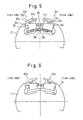
- FIG. 5 shows the condition in which upper teeth are open.
- Fig. 6 shows the condition in which the upper teeth are closed to tighten a printing plate.
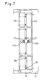
- Fig. 7 is a plan view of the manual printing plate-tightening device.
- a plate cylinder 01 is equipped with platetightening devices 03r and 03e.
- Each time the printed item is varied, a preparation time is required. This time greatly affects the rate of operation of a printing machine.
- a time taken to exchange the printing plate accounts for a considerable proportion of the preparation time.
- various devices have been invented.
- the time taken to exchange a printing plate differs considerably among printing sites. Statistics shows the average time.
- the time taken to operate an eccentric shaft, or cam shaft, for tightening a printing plate and bolts for stretching the plate accounts for most of the exchange time.
- the plate cylinder 01 is provided with a recess 02 in which the plate-tightening device 03r placed in the front portion and the tightening device 03e placed in the rear portion are received.
- the tightening device 03r has an upper tooth 05r, a lower tooth 04r, a pin 06r, a tightening cam 07r, and a bolt 08r for fine adjustment.
- the tightening device 03e has an upper tooth 05e, a lower tooth 04e, a tightening cam 07e, a bolt 08e for fine adjustment, and a plate-stretching cam 09.
- wrenches When the printing plate, indicated by numeral 10, is mounted or removed, wrenches are brought into engagement with wrench attachment portions 12r and 12e on the cam shafts 07r and 07e, respectively, which are mounted at the lateral center of the machine. Then, the wrenches are manually rotated through about 90°.
- an automatic printing plate-tightening device for use with a sheet-fed printing machine, said device having a plate cylinder, a cam shaft extending from one side surface of the cylinder, an arm mounted on the cam shaft, a pin mounted at the end of the arm, a first cylinder capable of rotating the arm about the cam shaft, and a second cylinder capable of changing the orientation of the first cylinder.
- the front end of the first cylinder can engage with the pin.
- the arm is rotated by the first cylinder to tighten or release a printing plate.
- the present tightening device After the completion of the installation of the printing plate, the present tightening device is held at its standby position so as not to hinder the printing operation.
- This series of operations is electrically controlled in a sequential manner.
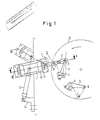
- FIG. 1 - 4 there is shown an automatic printing plate-tightening device according to the invention.
- a printing plate-tightening cam shaft 1 protrudes from one side of a plate cylinder 21.
- a front arm 2 is held to the cam shaft 1 by a bolt and a key.
- a pin 3 is mounted to the front end of the arm 2.
- another printing plate-tightening cam shaft 4 protrudes from the side surface of the plate cylinder 21.
- a rear arm 5 is rigidly fixed to the cam shaft 4.
- a pin 6 is affixed to the end of the arm 5.
- the closed position of the arm 2 is indicated by I, while the open position is indicated by II.
- the arm 2 is placed in position II, the front end of the printing plate is inserted between upper and lower teeth. Then, the arm 2 is returned to position I, thus fully tightening the front portion of the plate.
- a cylinder 7 acts to rotate the cam shaft 1, and consists of a hydraulic cylinder having a cylinder rod 8 whose rotation is limited.
- a metallic fixing member 9 is provided at the front end of the rod 8 to transmit its power to the pin 3.
- the cylinder 7 is coupled to a bracket 10 by an attachment 11.
- the bracket 10 serves to hold the cylinder 7, and is designed to be rotatable about a point C on a frame 22 via bearings (not shown).
- a locating cylinder 12 rotates the bracket 10 to vary the orientation of the cylinder 7.
- the front end of the rod of the cylinder 12 is connected to the bracket 10 via a pin 13 (Fig. 2).
- the rear end of the cylinder 12 is rigidly fixed to the frame 22 via a bracket 14.
- the center of rotation C of the cylinder 7 is so set that the front and rear cam shafts can be operated most appropriately by the cylinder 7.
- Fig. 1 shows the condition in which the present device has just begun to tighten the front portion of the printing plate.
- the rod of the cylinder 7 When the rod of the cylinder 7 is retracted, the upper tooth of the tightening device corresponding to the tooth 05r shown in Fig. 5 moves away from the opposite upper tooth (the arm 2 is moved into position II). Under this condition, the front portion of the printing plate is inserted into the tightening device. Then the rod of the cylinder 7 is advanced. This brings the arm 2 into position I, thus completing the tightening operation. During this process, the rod of the cylinder 12 is kept retracted, and the cylinder 12 is maintained at position III shown in Fig. 1.
- the plate cylinder 21 is made to make an approximately 3/4 revolution in the direction indicated by the arrow so that the plate may be wound on the cylinder 21.
- the orientation of the cylinder 7 is shifted from position III to IV by the cylinder 12.
- Fig. 3 shows the next step in which the present device has just begun to tighten the rear portion of the plate.
- the rod of the cylinder 7 is retracted as in the previous step to move the upper tooth of the tightening device corresponding to the tooth 05e shown in Fig. 5 away from the opposite tooth.
- the rear portion of the printing plate is inserted into the tightening device.
- the rod of the cylinder 7 is advanced.
- the tightening operation is completed.
- the rod of the cylinder 12 is maintained at its advanced position to hold the cylinder 7 at position IV.
- Fig. 4 shows the condition in which both the front portion and the rear portion of the printing plate have been fully tightened.
- the cylinder 7 is at its standby position so as not to hinder the printing operation.
- a separate device (not shown) is provided to maintain the plate cylinder at rest while the plate is tightened and released.
- the novel printing plate-tightening device for tightening the front and rear portions of the printing plate according to the present invention uses the two hydraulic cylinders. Hence, tightening both portions of the plate can be performed by the single device. In this way, the printing plate exchange operation is automated, thus saving labor. Also, no skillful operator is needed. In addition, the safety of the operation is enhanced. Furthermore, the exchange operation is performed in a shorter time than conventional. Additionally, the novel device has a simple structure and is economical to fabricate.
Landscapes
- Supply, Installation And Extraction Of Printed Sheets Or Plates (AREA)
Applications Claiming Priority (2)
| Application Number | Priority Date | Filing Date | Title |
|---|---|---|---|
| JP141428/86U | 1986-09-17 | ||
| JP1986141428U JPH0620609Y2 (ja) | 1986-09-17 | 1986-09-17 | 枚葉印刷機の自動版締め装置 |
Publications (3)
| Publication Number | Publication Date |
|---|---|
| EP0260492A2 true EP0260492A2 (de) | 1988-03-23 |
| EP0260492A3 EP0260492A3 (en) | 1989-08-23 |
| EP0260492B1 EP0260492B1 (de) | 1991-11-06 |
Family
ID=15291749
Family Applications (1)
| Application Number | Title | Priority Date | Filing Date |
|---|---|---|---|
| EP19870112340 Expired EP0260492B1 (de) | 1986-09-17 | 1987-08-25 | Automatische Druckplatten-Spannvorrichtung für Bogendruckmaschine |
Country Status (3)
| Country | Link |
|---|---|
| EP (1) | EP0260492B1 (de) |
| JP (1) | JPH0620609Y2 (de) |
| DE (1) | DE3774377D1 (de) |
Cited By (4)
| Publication number | Priority date | Publication date | Assignee | Title |
|---|---|---|---|---|
| DE3936458C1 (de) * | 1989-11-02 | 1991-04-11 | Man Roland Druckmaschinen Ag, 6050 Offenbach, De | |
| DE4111636C1 (de) * | 1991-04-10 | 1992-07-30 | Man Roland Druckmaschinen Ag, 6050 Offenbach, De | |
| DE4223328A1 (de) * | 1992-07-16 | 1994-02-03 | Roland Man Druckmasch | Vorrichtung zum Befestigen von Druckplatten auf dem Plattenzylinder von Druckmaschinen, insbesondere Bogenoffsetdruckmaschinen |
| EP0951994A1 (de) * | 1998-04-23 | 1999-10-27 | MAN Roland Druckmaschinen AG | Befestigungsvorrichtung für Platten auf Druckmaschinenzylindern |
Families Citing this family (3)
| Publication number | Priority date | Publication date | Assignee | Title |
|---|---|---|---|---|
| JP2565250Y2 (ja) * | 1990-09-27 | 1998-03-18 | 株式会社小森コーポレーション | 印刷機の版万力装置 |
| DE4137948A1 (de) * | 1990-11-19 | 1992-05-21 | Sumitomo Heavy Industries | Druckplatten-spannvorrichtung fuer eine druckmaschine |
| JP4829420B2 (ja) * | 2000-05-17 | 2011-12-07 | 株式会社小森コーポレーション | 印刷機 |
Family Cites Families (2)
| Publication number | Priority date | Publication date | Assignee | Title |
|---|---|---|---|---|
| JPH07378B2 (ja) * | 1982-04-29 | 1995-01-11 | 株式会社東京機械製作所 | 輪転印刷機の刷版自動着脱装置 |
| JPS6073850A (ja) * | 1983-09-26 | 1985-04-26 | Tokyo Kikai Seisakusho:Kk | 輪転機における刷版自動着脱装置 |
-
1986
- 1986-09-17 JP JP1986141428U patent/JPH0620609Y2/ja not_active Expired - Lifetime
-
1987
- 1987-08-25 DE DE8787112340T patent/DE3774377D1/de not_active Expired - Lifetime
- 1987-08-25 EP EP19870112340 patent/EP0260492B1/de not_active Expired
Cited By (4)
| Publication number | Priority date | Publication date | Assignee | Title |
|---|---|---|---|---|
| DE3936458C1 (de) * | 1989-11-02 | 1991-04-11 | Man Roland Druckmaschinen Ag, 6050 Offenbach, De | |
| DE4111636C1 (de) * | 1991-04-10 | 1992-07-30 | Man Roland Druckmaschinen Ag, 6050 Offenbach, De | |
| DE4223328A1 (de) * | 1992-07-16 | 1994-02-03 | Roland Man Druckmasch | Vorrichtung zum Befestigen von Druckplatten auf dem Plattenzylinder von Druckmaschinen, insbesondere Bogenoffsetdruckmaschinen |
| EP0951994A1 (de) * | 1998-04-23 | 1999-10-27 | MAN Roland Druckmaschinen AG | Befestigungsvorrichtung für Platten auf Druckmaschinenzylindern |
Also Published As
| Publication number | Publication date |
|---|---|
| JPH0620609Y2 (ja) | 1994-06-01 |
| DE3774377D1 (de) | 1991-12-12 |
| EP0260492B1 (de) | 1991-11-06 |
| JPS6347134U (de) | 1988-03-30 |
| EP0260492A3 (en) | 1989-08-23 |
Similar Documents
| Publication | Publication Date | Title |
|---|---|---|
| US4807527A (en) | Printing machine cylinder holder arrangement | |
| JP2926656B2 (ja) | 枚葉印刷機の版ひねり調整機構 | |
| US5623877A (en) | Method and apparatus for preparing a printing plate | |
| EP0260492B1 (de) | Automatische Druckplatten-Spannvorrichtung für Bogendruckmaschine | |
| GB2122580A (en) | Turnover apparatus | |
| CA1289814C (en) | Adjustable bearing arrangement for a printing machine cylinder | |
| US4346655A (en) | Device for exchanging the form cylinder in a photogravure rotary machine | |
| CA2042943C (en) | Apparatus and method for printing plate cylinder -- impression cylinder registration | |
| GB936437A (en) | Throw-off mechanism for offset presses | |
| US5644983A (en) | Coupling arrangement for coupling printing stands to one another in a printing press and method for coupling printing stands to one another in a printing press | |
| JP3183535B2 (ja) | 金型自動交換システムにおける金型自動固定装置 | |
| CA1081505A (en) | Lathe apparatus | |
| US4018158A (en) | Universal master cylinder for offset presses | |
| CN1003118B (zh) | 旋转压力机的卷板筒上的夹紧条 | |
| US4881398A (en) | Transfer press | |
| JPS62221542A (ja) | 刷版案内装置 | |
| JPS55100839A (en) | Turn-around mechanism for press working | |
| US3217131A (en) | Tiltable die supporting apparatus | |
| EP0045374B1 (de) | Greifereinrichtung an Zylindern für Druckmaschinen, insbesondere Bogenrotationsdruckmaschinen | |
| CN219403102U (zh) | 一种锁具锁芯装配用推进机构及其进料装置 | |
| CN214757134U (zh) | 一种电路板加工用快速定位治具 | |
| CN214322201U (zh) | 一种机械零部件加工用表面打标装置 | |
| KR100234155B1 (ko) | 가공소재 로딩장치 | |
| CN220944030U (zh) | 一种铸件螺套装配装置 | |
| US5404804A (en) | Offset printing machine with number printing function |
Legal Events
| Date | Code | Title | Description |
|---|---|---|---|
| PUAI | Public reference made under article 153(3) epc to a published international application that has entered the european phase |
Free format text: ORIGINAL CODE: 0009012 |
|
| 17P | Request for examination filed |
Effective date: 19870922 |
|
| AK | Designated contracting states |
Kind code of ref document: A2 Designated state(s): DE FR GB IT |
|
| PUAL | Search report despatched |
Free format text: ORIGINAL CODE: 0009013 |
|
| AK | Designated contracting states |
Kind code of ref document: A3 Designated state(s): DE FR GB IT |
|
| 17Q | First examination report despatched |
Effective date: 19910306 |
|
| GRAA | (expected) grant |
Free format text: ORIGINAL CODE: 0009210 |
|
| ITF | It: translation for a ep patent filed | ||
| AK | Designated contracting states |
Kind code of ref document: B1 Designated state(s): DE FR GB IT |
|
| REF | Corresponds to: |
Ref document number: 3774377 Country of ref document: DE Date of ref document: 19911212 |
|
| ET | Fr: translation filed | ||
| PLBE | No opposition filed within time limit |
Free format text: ORIGINAL CODE: 0009261 |
|
| STAA | Information on the status of an ep patent application or granted ep patent |
Free format text: STATUS: NO OPPOSITION FILED WITHIN TIME LIMIT |
|
| 26N | No opposition filed | ||
| PGFP | Annual fee paid to national office [announced via postgrant information from national office to epo] |
Ref country code: DE Payment date: 19980831 Year of fee payment: 12 |
|
| PG25 | Lapsed in a contracting state [announced via postgrant information from national office to epo] |
Ref country code: DE Free format text: LAPSE BECAUSE OF NON-PAYMENT OF DUE FEES Effective date: 20000601 |
|
| REG | Reference to a national code |
Ref country code: GB Ref legal event code: IF02 |
|
| PG25 | Lapsed in a contracting state [announced via postgrant information from national office to epo] |
Ref country code: IT Free format text: LAPSE BECAUSE OF NON-PAYMENT OF DUE FEES;WARNING: LAPSES OF ITALIAN PATENTS WITH EFFECTIVE DATE BEFORE 2007 MAY HAVE OCCURRED AT ANY TIME BEFORE 2007. THE CORRECT EFFECTIVE DATE MAY BE DIFFERENT FROM THE ONE RECORDED. Effective date: 20050825 |
|
| PGFP | Annual fee paid to national office [announced via postgrant information from national office to epo] |
Ref country code: FR Payment date: 20060808 Year of fee payment: 20 |
|
| PGFP | Annual fee paid to national office [announced via postgrant information from national office to epo] |
Ref country code: GB Payment date: 20060823 Year of fee payment: 20 |
|
| REG | Reference to a national code |
Ref country code: GB Ref legal event code: PE20 |
|
| PG25 | Lapsed in a contracting state [announced via postgrant information from national office to epo] |
Ref country code: GB Free format text: LAPSE BECAUSE OF EXPIRATION OF PROTECTION Effective date: 20070824 |