EP0260496A2 - Kraftübertragung für ein Fahrzeug mit Allradantrieb - Google Patents
Kraftübertragung für ein Fahrzeug mit Allradantrieb Download PDFInfo
- Publication number
- EP0260496A2 EP0260496A2 EP87112495A EP87112495A EP0260496A2 EP 0260496 A2 EP0260496 A2 EP 0260496A2 EP 87112495 A EP87112495 A EP 87112495A EP 87112495 A EP87112495 A EP 87112495A EP 0260496 A2 EP0260496 A2 EP 0260496A2
- Authority
- EP
- European Patent Office
- Prior art keywords
- hydraulic oil
- vehicle
- drive force
- rotation speed
- rotary shaft
- Prior art date
- Legal status (The legal status is an assumption and is not a legal conclusion. Google has not performed a legal analysis and makes no representation as to the accuracy of the status listed.)
- Granted
Links
Images

Classifications
-
- B—PERFORMING OPERATIONS; TRANSPORTING
- B60—VEHICLES IN GENERAL
- B60K—ARRANGEMENT OR MOUNTING OF PROPULSION UNITS OR OF TRANSMISSIONS IN VEHICLES; ARRANGEMENT OR MOUNTING OF PLURAL DIVERSE PRIME-MOVERS IN VEHICLES; AUXILIARY DRIVES FOR VEHICLES; INSTRUMENTATION OR DASHBOARDS FOR VEHICLES; ARRANGEMENTS IN CONNECTION WITH COOLING, AIR INTAKE, GAS EXHAUST OR FUEL SUPPLY OF PROPULSION UNITS IN VEHICLES
- B60K17/00—Arrangement or mounting of transmissions in vehicles
- B60K17/34—Arrangement or mounting of transmissions in vehicles for driving both front and rear wheels, e.g. four wheel drive vehicles
- B60K17/348—Arrangement or mounting of transmissions in vehicles for driving both front and rear wheels, e.g. four wheel drive vehicles having differential means for driving one set of wheels, e.g. the front, at one speed and the other set, e.g. the rear, at a different speed
-
- F—MECHANICAL ENGINEERING; LIGHTING; HEATING; WEAPONS; BLASTING
- F16—ENGINEERING ELEMENTS AND UNITS; GENERAL MEASURES FOR PRODUCING AND MAINTAINING EFFECTIVE FUNCTIONING OF MACHINES OR INSTALLATIONS; THERMAL INSULATION IN GENERAL
- F16H—GEARING
- F16H48/00—Differential gearings
- F16H48/20—Arrangements for suppressing or influencing the differential action, e.g. locking devices
- F16H48/27—Arrangements for suppressing or influencing the differential action, e.g. locking devices using internally-actuatable fluid pressure, e.g. internal pump types
-
- B—PERFORMING OPERATIONS; TRANSPORTING
- B60—VEHICLES IN GENERAL
- B60K—ARRANGEMENT OR MOUNTING OF PROPULSION UNITS OR OF TRANSMISSIONS IN VEHICLES; ARRANGEMENT OR MOUNTING OF PLURAL DIVERSE PRIME-MOVERS IN VEHICLES; AUXILIARY DRIVES FOR VEHICLES; INSTRUMENTATION OR DASHBOARDS FOR VEHICLES; ARRANGEMENTS IN CONNECTION WITH COOLING, AIR INTAKE, GAS EXHAUST OR FUEL SUPPLY OF PROPULSION UNITS IN VEHICLES
- B60K17/00—Arrangement or mounting of transmissions in vehicles
- B60K17/34—Arrangement or mounting of transmissions in vehicles for driving both front and rear wheels, e.g. four wheel drive vehicles
- B60K17/348—Arrangement or mounting of transmissions in vehicles for driving both front and rear wheels, e.g. four wheel drive vehicles having differential means for driving one set of wheels, e.g. the front, at one speed and the other set, e.g. the rear, at a different speed
- B60K17/35—Arrangement or mounting of transmissions in vehicles for driving both front and rear wheels, e.g. four wheel drive vehicles having differential means for driving one set of wheels, e.g. the front, at one speed and the other set, e.g. the rear, at a different speed including arrangements for suppressing or influencing the power transfer, e.g. viscous clutches
- B60K17/3505—Arrangement or mounting of transmissions in vehicles for driving both front and rear wheels, e.g. four wheel drive vehicles having differential means for driving one set of wheels, e.g. the front, at one speed and the other set, e.g. the rear, at a different speed including arrangements for suppressing or influencing the power transfer, e.g. viscous clutches with self-actuated means, e.g. by difference of speed
-
- F—MECHANICAL ENGINEERING; LIGHTING; HEATING; WEAPONS; BLASTING
- F16—ENGINEERING ELEMENTS AND UNITS; GENERAL MEASURES FOR PRODUCING AND MAINTAINING EFFECTIVE FUNCTIONING OF MACHINES OR INSTALLATIONS; THERMAL INSULATION IN GENERAL
- F16H—GEARING
- F16H48/00—Differential gearings
- F16H48/12—Differential gearings without gears having orbital motion
- F16H48/18—Differential gearings without gears having orbital motion with fluid gearing
Definitions
- pressure of hydraulic oil delivered from the hydraulic oil pump is controlled to obtain a drive force transmitted to the rear wheels (or front wheels) matching the running conditions of the vehicle.
- the drive force is transmitted to the rear wheels in dependence on a relative difference in rotation speed between the drive shaft transmitting the drive force to the front wheels and that transmitting the drive force to the rear wheels. Therefore, when the vehicle is running at a constant speed in which the drive force is directly transmitted from the engine to the front wheels, the rotary shaft for the rear wheels rotates at the same rotation speed as the rotary shaft for the front wheels, and a floating condition occurs in which no drive force is transmitted to the rear wheels.
- a power transmission apparatus for a vehicle of four-wheel drive type comprising a first rotary shaft for transmitting drive force to front wheels, a second rotary shaft for transmitting drive force to rear wheels, a hydraulic oil pump used as connecting means for connecting the first and second rotary shafts, which is driven by a difference in rotation speed between the first and second rotary shafts to deliver hydraulic oil of an amount depending on the rotation speed difference and has a suction passage and a delivery passage which are changed over according to the relative rotational direction of the first and second rotary shafts, restricting means for restricting pressure of hydraulic oil delivered from the hydraulic oil pump, and an expansion chamber connected to the suction passage and delivery passage for reserving hydraulic oil to temporarily suppress increase in pressure of hydraulic oil delivered from the hydraulic oil pump.
- the drive force is not transmitted for a short period of time until the expansion chamber is filled with hydraulic oil, and if the rear wheel drive system is in a floating state and a small variation in rotation speed occurs in the first rotary shaft, the variation in rotation speed is absorbed by the function of the expansion chamber and not transmitted to the second rotary shaft, thereby preventing occurrence of unusual noises such as a hammering noise in the rear wheel drive system and improving the durability of the rear wheel drive system.
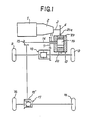
- Fig.1 is a schematic view showing the structure of a drive system for a vehicle provided with the power transmission apparatus according to the present invention.
- a transmission mechanism is connected to an engine 1 having a crankshaft extending in the widthwise direction of the vehicle, and an output shaft 3 of the transmission mechanism 2 transmits drive force to a drive gear (or a 4th speed counter gear) 4 mounted thereon. From the drive gear 4, the drive force is transmitted to a cam ring gear 20e of a power transmission apparatus body 13.
- the cam ring gear 20e drives a housing 20, and, through a first rotary shaft (an outer shaft) 11 coupled to the housing 20, the drive force is transmitted to a gear 7. From the gear 7, the drive force is transmitted to a differential unit 10 for front wheels 9 to drive the front wheels 9.
- the drive force transmitted to the power transmission apparatus body 13 is transmitted intact to the first rotary shaft 11 through the cam ring gear 20e and is transmitted then to the front wheels 9 through the gear 7 and differential unit 10.
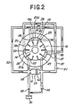
- the hydraulic control circuit 21 has a suction passage 51 and a delivery passage 53.
- the suction passage 51 makes communication of the suction ports 23, 25, and 27 shown in Fig.2 with each other, and connects these suction ports 23, 25, and 27 to an oil reservoir 30.
- the delivery passage 53 makes communication of the suction ports 24, 25, and 26 shown in Fig.2 with each other, and connects these suction ports 24, 25, and 26 to the oil reservoir 30.
- Check valves 29 and 28 which permit flow from the oil reservoir 30 only are disposed at connections of the suction passage 51 and the delivery passage 53 to the oil reservoir 30.
- the suction passage 51 and the delivery passage 53 communicate with each other through an oil path 55, and the oil path 55 is provided with an orifice 57 which restricts oil flow between the delivery passage 53 and the suction passage 51.
- the hydraulic acid is also conducted to the orifice 57 of the oil path 55 and the free piston 59 of the oil path 58 to provide the same actions as described above.
- the drive force is transmitted to the rear wheels 16 thereby establishing the four-wheel drive mode, and the braking torque to the rear wheels 16 is increased thereby preventing the front wheels 9 from locking.
- hydraulic oil delivered into the suction passage 51 moves the piston 63 of the free piston 59 from the right to the left in Fig.2 thereby retarding increase in delivery pressure of hydraulic oil temporarily.
- hydraulic oil delivered into the delivery passage 53 moves the piston 63 of the free piston 59 from the left to the right in Fig.2 thereby retarding increase in delivery pressure of hydraulic oil temporarily.
Landscapes
- Engineering & Computer Science (AREA)
- General Engineering & Computer Science (AREA)
- Mechanical Engineering (AREA)
- Chemical & Material Sciences (AREA)
- Combustion & Propulsion (AREA)
- Transportation (AREA)
- Physics & Mathematics (AREA)
- Fluid Mechanics (AREA)
- Arrangement And Driving Of Transmission Devices (AREA)
Applications Claiming Priority (2)
| Application Number | Priority Date | Filing Date | Title |
|---|---|---|---|
| JP61205300A JPS6361632A (ja) | 1986-09-01 | 1986-09-01 | 全輪駆動用駆動連結装置 |
| JP205300/86 | 1986-09-01 |
Publications (3)
| Publication Number | Publication Date |
|---|---|
| EP0260496A2 true EP0260496A2 (de) | 1988-03-23 |
| EP0260496A3 EP0260496A3 (en) | 1988-08-31 |
| EP0260496B1 EP0260496B1 (de) | 1990-08-22 |
Family
ID=16504677
Family Applications (1)
| Application Number | Title | Priority Date | Filing Date |
|---|---|---|---|
| EP87112495A Expired - Lifetime EP0260496B1 (de) | 1986-09-01 | 1987-08-27 | Kraftübertragung für ein Fahrzeug mit Allradantrieb |
Country Status (5)
| Country | Link |
|---|---|
| US (1) | US4881626A (de) |
| EP (1) | EP0260496B1 (de) |
| JP (1) | JPS6361632A (de) |
| KR (1) | KR920007462B1 (de) |
| DE (1) | DE3764437D1 (de) |
Cited By (1)
| Publication number | Priority date | Publication date | Assignee | Title |
|---|---|---|---|---|
| AU637920B2 (en) * | 1990-07-27 | 1993-06-10 | Joy Manufacturing Company (Africa) (Proprietary) Limited | Drive train |
Families Citing this family (3)
| Publication number | Priority date | Publication date | Assignee | Title |
|---|---|---|---|---|
| US5074825A (en) * | 1989-03-20 | 1991-12-24 | Koyo Seiko Co., Ltd. | Hydraulic transmission coupling apparatus |
| JPH039155A (ja) * | 1989-06-07 | 1991-01-17 | Koyo Seiko Co Ltd | 4輪駆動用駆動連結装置 |
| JP2504322Y2 (ja) * | 1990-03-15 | 1996-07-10 | 光洋精工株式会社 | 4輪駆動用駆動連結装置 |
Family Cites Families (16)
| Publication number | Priority date | Publication date | Assignee | Title |
|---|---|---|---|---|
| US28324A (en) * | 1860-05-15 | Sachusetts | ||
| US2595479A (en) * | 1946-10-09 | 1952-05-06 | Foote Bros Gear And Machine Co | Radially movable piston type clutch |
| US3272276A (en) * | 1964-04-17 | 1966-09-13 | Budzich Tadeusz | Fluid power synchronized drives for vehicles |
| US3447619A (en) * | 1966-12-05 | 1969-06-03 | Flex Track Equipment Ltd | Transmission for four-tracked vehicles |
| USRE28324E (en) | 1969-01-23 | 1975-01-28 | Hydraulic drivk for multi-axle vehicles | |
| US3680652A (en) * | 1971-01-14 | 1972-08-01 | Clarence Kirk Greene | Hydraulic drive for multi-axle vehicles |
| FR2190220A5 (de) * | 1972-06-23 | 1974-01-25 | Gkn Transmissions Ltd | |
| SU626239A1 (ru) * | 1977-04-04 | 1978-09-30 | Всесоюзный научно-исследовательский и проектно-конструкторский институт промышленных гидроприводов и гидроавтоматики | Гидромотор |
| US4272993A (en) * | 1978-10-11 | 1981-06-16 | General Motors Corporation | Hydraulically controlled differential |
| JPS5957032A (ja) * | 1982-09-27 | 1984-04-02 | Mazda Motor Corp | 四輪駆動車 |
| GB2142592B (en) * | 1983-06-08 | 1987-01-21 | Jaguar Cars | Four-wheel drive vehicle transmission system |
| US4676336A (en) * | 1983-11-11 | 1987-06-30 | Mitsubishi Jidosha Kogyo Kabushiki Kaisha | Power transmission apparatus for vehicle |
| FR2554768B1 (fr) * | 1983-11-11 | 1991-11-22 | Mitsubishi Motors Corp | Dispositif de transmission de puissance destine a un vehicule |
| JPS61166729A (ja) * | 1985-01-16 | 1986-07-28 | Toyota Motor Corp | 四輪駆動車用動力伝達装置 |
| IT1290813B1 (it) * | 1997-03-24 | 1998-12-11 | Rollon S P A | Cuscinetto lineare con guida a c a piste contrapposte di cui una pista con superficie a porzione di cilindro |
| JPH116525A (ja) * | 1997-06-17 | 1999-01-12 | Mitsutoyo Corp | 流体軸受装置 |
-
1986
- 1986-09-01 JP JP61205300A patent/JPS6361632A/ja active Granted
-
1987
- 1987-07-10 KR KR1019870007421A patent/KR920007462B1/ko not_active Expired
- 1987-08-27 DE DE8787112495T patent/DE3764437D1/de not_active Expired - Lifetime
- 1987-08-27 EP EP87112495A patent/EP0260496B1/de not_active Expired - Lifetime
-
1989
- 1989-01-24 US US07/302,037 patent/US4881626A/en not_active Expired - Fee Related
Cited By (1)
| Publication number | Priority date | Publication date | Assignee | Title |
|---|---|---|---|---|
| AU637920B2 (en) * | 1990-07-27 | 1993-06-10 | Joy Manufacturing Company (Africa) (Proprietary) Limited | Drive train |
Also Published As
| Publication number | Publication date |
|---|---|
| DE3764437D1 (de) | 1990-09-27 |
| KR880003772A (ko) | 1988-05-30 |
| KR920007462B1 (ko) | 1992-09-03 |
| JPS6361632A (ja) | 1988-03-17 |
| EP0260496B1 (de) | 1990-08-22 |
| JPH0464887B2 (de) | 1992-10-16 |
| EP0260496A3 (en) | 1988-08-31 |
| US4881626A (en) | 1989-11-21 |
Similar Documents
| Publication | Publication Date | Title |
|---|---|---|
| US4727966A (en) | Differential with differential motion limiting mechanism | |
| US4676336A (en) | Power transmission apparatus for vehicle | |
| US5916052A (en) | Hydromechanical system for limiting differential speed between differentially rotating members | |
| US6161643A (en) | System of controlling torque transfer in a motor vehicle and related method | |
| EP0260496B1 (de) | Kraftübertragung für ein Fahrzeug mit Allradantrieb | |
| US6544136B2 (en) | Differential device | |
| JP2555489B2 (ja) | 4輪駆動車両の動力伝達装置 | |
| JPS60116529A (ja) | 四輪駆動用駆動連結装置 | |
| JPH038499Y2 (de) | ||
| KR890001336B1 (ko) | 차동장치의 차동 제한기구 | |
| JPH0567817B2 (de) | ||
| JPS60116526A (ja) | 4輪駆動用駆動連結装置 | |
| JPH0118418Y2 (de) | ||
| JPS60104426A (ja) | 4輪駆動用駆動連結装置 | |
| JPH0215699Y2 (de) | ||
| JPH0324903Y2 (de) | ||
| JPH0324904Y2 (de) | ||
| JPH0620827B2 (ja) | 4輪駆動車用トランスフアクラツチ装置 | |
| JPH0139226Y2 (de) | ||
| JPH038498Y2 (de) | ||
| JPH0435366B2 (de) | ||
| JPS60176825A (ja) | 4輪駆動用駆動連結装置 | |
| JPH0423055Y2 (de) | ||
| JP2779939B2 (ja) | ベーンクラッチ | |
| JPH0344581Y2 (de) |
Legal Events
| Date | Code | Title | Description |
|---|---|---|---|
| PUAI | Public reference made under article 153(3) epc to a published international application that has entered the european phase |
Free format text: ORIGINAL CODE: 0009012 |
|
| AK | Designated contracting states |
Kind code of ref document: A2 Designated state(s): DE FR GB |
|
| PUAL | Search report despatched |
Free format text: ORIGINAL CODE: 0009013 |
|
| AK | Designated contracting states |
Kind code of ref document: A3 Designated state(s): DE FR GB |
|
| 17P | Request for examination filed |
Effective date: 19880830 |
|
| 17Q | First examination report despatched |
Effective date: 19891006 |
|
| GRAA | (expected) grant |
Free format text: ORIGINAL CODE: 0009210 |
|
| AK | Designated contracting states |
Kind code of ref document: B1 Designated state(s): DE FR GB |
|
| REF | Corresponds to: |
Ref document number: 3764437 Country of ref document: DE Date of ref document: 19900927 |
|
| ET | Fr: translation filed | ||
| PLBE | No opposition filed within time limit |
Free format text: ORIGINAL CODE: 0009261 |
|
| STAA | Information on the status of an ep patent application or granted ep patent |
Free format text: STATUS: NO OPPOSITION FILED WITHIN TIME LIMIT |
|
| 26N | No opposition filed | ||
| PGFP | Annual fee paid to national office [announced via postgrant information from national office to epo] |
Ref country code: FR Payment date: 20000811 Year of fee payment: 14 |
|
| PGFP | Annual fee paid to national office [announced via postgrant information from national office to epo] |
Ref country code: DE Payment date: 20000822 Year of fee payment: 14 |
|
| PGFP | Annual fee paid to national office [announced via postgrant information from national office to epo] |
Ref country code: GB Payment date: 20000823 Year of fee payment: 14 |
|
| PG25 | Lapsed in a contracting state [announced via postgrant information from national office to epo] |
Ref country code: GB Free format text: LAPSE BECAUSE OF NON-PAYMENT OF DUE FEES Effective date: 20010827 |
|
| GBPC | Gb: european patent ceased through non-payment of renewal fee |
Effective date: 20010827 |
|
| PG25 | Lapsed in a contracting state [announced via postgrant information from national office to epo] |
Ref country code: FR Free format text: LAPSE BECAUSE OF NON-PAYMENT OF DUE FEES Effective date: 20020430 |
|
| PG25 | Lapsed in a contracting state [announced via postgrant information from national office to epo] |
Ref country code: DE Free format text: LAPSE BECAUSE OF NON-PAYMENT OF DUE FEES Effective date: 20020501 |
|
| REG | Reference to a national code |
Ref country code: FR Ref legal event code: ST |