EP0260659A2 - Micro-interrupteur - Google Patents
Micro-interrupteur Download PDFInfo
- Publication number
- EP0260659A2 EP0260659A2 EP87113480A EP87113480A EP0260659A2 EP 0260659 A2 EP0260659 A2 EP 0260659A2 EP 87113480 A EP87113480 A EP 87113480A EP 87113480 A EP87113480 A EP 87113480A EP 0260659 A2 EP0260659 A2 EP 0260659A2
- Authority
- EP
- European Patent Office
- Prior art keywords
- switch
- movable
- actuator
- contact
- push
- Prior art date
- Legal status (The legal status is an assumption and is not a legal conclusion. Google has not performed a legal analysis and makes no representation as to the accuracy of the status listed.)
- Withdrawn
Links
Images


Classifications
-
- H—ELECTRICITY
- H01—ELECTRIC ELEMENTS
- H01H—ELECTRIC SWITCHES; RELAYS; SELECTORS; EMERGENCY PROTECTIVE DEVICES
- H01H13/00—Switches having rectilinearly-movable operating part or parts adapted for pushing or pulling in one direction only, e.g. push-button switch
- H01H13/02—Details
- H01H13/12—Movable parts; Contacts mounted thereon
- H01H13/14—Operating parts, e.g. push-button
- H01H13/18—Operating parts, e.g. push-button adapted for actuation at a limit or other predetermined position in the path of a body, the relative movement of switch and body being primarily for a purpose other than the actuation of the switch, e.g. door switch, limit switch, floor-levelling switch of a lift
- H01H13/186—Operating parts, e.g. push-button adapted for actuation at a limit or other predetermined position in the path of a body, the relative movement of switch and body being primarily for a purpose other than the actuation of the switch, e.g. door switch, limit switch, floor-levelling switch of a lift wherein the pushbutton is rectilinearly actuated by a lever pivoting on the housing of the switch
-
- H—ELECTRICITY
- H01—ELECTRIC ELEMENTS
- H01H—ELECTRIC SWITCHES; RELAYS; SELECTORS; EMERGENCY PROTECTIVE DEVICES
- H01H13/00—Switches having rectilinearly-movable operating part or parts adapted for pushing or pulling in one direction only, e.g. push-button switch
- H01H13/02—Details
- H01H13/26—Snap-action arrangements depending upon deformation of elastic members
- H01H13/28—Snap-action arrangements depending upon deformation of elastic members using compression or extension of coil springs
Definitions
- the prior art microswitch shown in Fig. 5 has a movable contact 51 which is provided at an end of movable piece 54.
- the other end of the movable piece 54 is fixed at an end of holding piece 53.
- the movable piece 54 can swing around the holding piece 53 which is a portion of a common terminal 52.
- Fixed contacts 55 and 56 are connected to fixed terminals 57 and 58, respectively.
- a coil spring 60 is provided between standing member 59 and a middle portion of movable piece 54.
- a push-button 61 is disposed to push the coil spring 60 in the free position of the switch, wherein the movable contact 51 is on the upper fixed contact 55. If the push-button 61 is pressed down the coil spring 60 is distorted downwardly so that the movable piece 54 is clicked down around the other end to make the movable contact 51 with the fixed contact 56, thus, performing a switching operation.
- FIG. 6 shows another type of conventional microswitch.
- a movable piece 64 has a movable contact 62 and a movable plate spring 63, one end of which rests on a holding piece 69 which is made in one piece with a common terminal 70.
- Fixed contacts 65 and 60 are connected to fixed terminal 67 and 68, respectively.
- Push-button 72 is provided to push receiving member 71, both ends of which are connected to common terminal 70 and the end portion of movable piece 64. In the free position of this switch a movable contact 62 rests on fixed contact 65.
- push-button 72 is pushed down, the end of movable piece 64 is moved downwardly through the receiving member 71.
- movable plate spring 63 turns around to make its movable contact 62 with fixed contact 60.
- the switch shown in Fig. 5 is simple in construction, but in its switching operation, movable piece 54 swings around a holding piece, so that a wiping effect by movable contact 51 cannot be expected.
- the wiping effect of movable contact 51 is necessary for avoiding the welding of contacts often observed in type of high-capacity switch. More specifically, an arc flows between contacts when a switch makes and breaks to weld the contacts. Wiping is required to remove melted substance from the surface of contacts and to improve the reliability of switch operation.
- the swinging point of receiving member 71 is located under the conjunction point of receiving member 71 and movable piece 64, so that when push-button 72 is pressed down, the movable piece 64 moves a little bit backward. Therefore, when the movable contact 62 comes away from fixed contact 65, it can have a wiping effect on the fixed contact 65.
- this type of switch needs receiving member 71, which makes the structure more complicated.
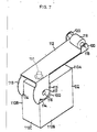
- the actuator 18 which is positioned to cover the push-button 12 can be modified as shown in Figs. 7-9. Initially, however, an actuator in the prior art has been illustrated in Figs. 10-11. Shown in Fig. 10 is a switch having a switching mechanism contained in case 101 which has a push-button 102 and an actuator 103 for pressing on the button 102.
- the actuator 103 is a metal plate, a portion of which is folded downwardly to form a regulating member 104.
- a pair of actuator portions 105 are formed as supporting members for the actuator 103, while the other end of the actuator 103 is folded to form a pair of roller supporting members 109. Both sides 101B of the case 101 have cuts 101D at the corners of case 101.
- a pin 106 is formed with one piece with the case 101 to permit the supporting members 105 to be rotatably engaged.
- a roller 108 has a rotary shaft 107 which is coupled to roller supporting member 109.
- the actuator 103 which is rotatably supported by the pin 106 is positioned over the push-button 102. Normally, the actuator 103 is held up by the restoring force of the push-button 102. When an object hits the roller 108, the actuator 103 moves around pin 106 and pushes the push-button 102 against its restoring force, thus, operating the contact switching mechanism housed within the case 101. After the depressing force is removed from the actuator 103, the actuator 103 is instantly raised by the restoring force of push-button 102.
- the regulating member 104 When the actuator 103 rotates, the regulating member 104 contacts side 101C of the case 101 in order to stop the rotation of the actuator 103.
- the regulating member 104 as shown in Fig. 10, has problems adjusting the rotation of the actuator 103 due to an unstable folding angle.
- the regulating member 104 when the actuator 103 is held up in a forceful manner, the regulating member 104 is pressed against side 101C of the case 101, thereby, distorting the regulating member 104. Therefore, the switch illustrated in Figs. 10 and 11 is highly unreliable.
- this invention further provides a switch having a regulating member for rotating an actuator which can be manufactured with significant accuracy.
- the switch of the instant invention is highly capable of maintaining its reliability during operation.
- the switch of the instant invention comprises a switch having an outwardly protruding push-button for operating a contact switching mechanism housed within the case.
- an actuator having at one end a pair of supporting members folded downwardly and rotatably engaged with the case, whereby the other end of the actuator is a free end.
- the supporting members of the actuator are formed in one piece with the regulating member which contacts one side of the case in order to stop the rotation of the actuator.
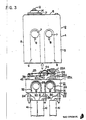
- the switch of this invention is divided into two parts as shown in Fig. 3, i.e., switch 1 and cover 2, which are designed to be separately assembled before the switch 1 is inserted into the cover 2.
- Cover 2 has slide walls 3, front wall 4, rear wall 5, and upper wall 6.
- the bottom of cover 2 has an opening into which the switch 1 is inserted.
- a pair of side walls 3 has two attachment passing holes 7 therethrough and two engagement holes 8.
- the internal surfaces of front wall 4 and rear wall 5 have steps 10 for positioning the upper limit of switch 1 inserted from the bottom of cover 2 and projections 11 for positioning the lower limit of switch 1.
- the upper wall 6 has a hole 13 through which a push-button 12 is attached to cover 2 through a water-resistant rubber cap 14.
- the cap 14 is tightly engaged in the groove 15 formed around the push-button 12.
- the lower portion of cap 14 is engaged in groove 16 which surrounds the hole 13.
- Another holding piece 17 presses the end of cap 14 over the groove 16. In this way, the push-button 12 is biased upwardly by elasticity of cap 16.
- actuator 18 An end of actuator 18 is rotatably attached to the upper portion of cover 2.
- Actuator 18 is positioned to cover the push-button 12.
- the other end of the actuator 18 has a roller 19, the shaft 20 of which is rotatably mounted thereto.
- Switch 1 is made up of base 21 made of resin, usually epoxy resin, a normally closed fixed terminal 22, a normally open fixed terminal 23, a common terminal 24, a movable coil spring 25, and a movable piece 26.
- the base 21 has a passing through holes 29 which pass through between side surfaces 27 and 28 and confront face-to-face with attachment holes 7 to cover 2.
- the side surfaces 27 and 28 have engagement hooks 30 which engage with engagement holes 8.
- Side surfaces 27 and 28 of switch 1 have elevated areas 31 which meet with the groove 9 formed on an internal surface of side walls 3 of cover 2. Detent or button upon assembly engages with hole 8.
- a lead-groove for seal 32 is provided which goes from the bottom of base 21, turns around passing through hole 29 and returns to the bottom of base 21.
- the base 21 has three vertical passing-through holes 34, 35, and 36 into which the common terminal 24, normally open fixed terminal 23 and normally closed fixed terminal 22 are pressed, respectively.
- Normally closed terminal 22 and normally open terminal 23 have fixed contacts 22a and 23a, respectively, facing to each other at one end of each terminal. The other ends of terminals extend dowwardly.
- the common terminal 24 has a standing piece 43 and folding piece 37 at one end, while the other end of common terminal 24 extends downwardly.
- a movable coil spring 25 made of piano wire is mounted in a tensioned condition with one and hooked in hole 38 in standing piece 43 and the other end hooked in hole 39 defined in movable piece 26.
- the movable piece 26 has a movable plate coil 44 which stands out of movable piece 26 and fitted into a dent formed in a holding piece 37.
- a movable contact 26a is attached to an end of movable piece 26 which is biased by the movable plate coil 44 so as to make the movable contact 26 contact with the fixed contact 22a.
- Each terminal 22, 23 and 24 extending downwardly is soldered to lead 41. In this way, separately assembled switch body 1 and cover 2 are coupled by inserting switch body 1 into cover 2.
- switch body 1 is designed to fit within the internal surface of cover 2 to have each side surface thereof contacted with the counterpart of cover 2.
- the insertion of switch body 1 continues until upper surface of switch body 1 lands into step 10 on switch cover 2.
- the projection 11 projects under switch body 1 thereby positioning the body 1 in the cover 2.
- the bottom portion of push-button 12 rests on the upper portion of movable coil spring 25 and the attachment holes 7 of cover 2 confront face-to-face with the passing through holes 29 of switch 1.
- the engagement hook 30 of switch body 1 is fitted in the engagement hole 8 of cover 2 to strengthen the condition of their coupling.
- the internal groove 9 of cover 2 is filled with elevated areas 31 of switch body 1.
- the sealing resin for example epoxy resin
- the switch body 1 is fixed in the cover 2 with its terminals 22, 23 and 34 soldered to lead 41.
- the resin is injected into cover 2, it passes through the lead-groove for seal 32 and secures the seal around the passing through holes 7 and 29 respectively defined in cover 2 and switch body 1, as well as the contacting portion between the engagement hole 8 and engagement hook 30, thereby preventing water coming therefrom.
- a switch assembled in this way is mounted to an appliance for use by driving screws into holes 7 and 29.
- actuator 18 When an object strikes against roller 19 and actuator 18 is pressed down to depress push-button 12, the lower portion of push-button 12 presses the movable coil spring 25. If the push-button 12 passes over a certain point, then the movable plate coil 44 turns around to make the movable contact 26a come into contact with fixed contact 23a.
- the push-button 12 is pushed up by the restoring force of movable coil spring 25 and the movable plate spring 44 turns around to bring the movable contact 26a again into contact with the fixed contact 22a.
- a case 110 is shown preferably made out of resin for housing a contact switching mechanism.
- a top wall 110A of case 110 has a push-button 111 outwardly protruding therefrom.
- An actuator 112 is rotably supported at one end so as to be capable of pressing the push-button 111.
- the actuator 112 has at one end a pair of metal portions which are downwardly folded to form a pair of supporting members 113.
- a pair of metal portions at the other end of the actuator 112 are upwardly folded to form roller supporting members 120.
- cuts 110D are provided for receiving supporting members 113.
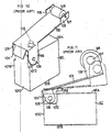
- a pair of pins 116 protrude to engage with holes 117 defined in the supporting members 113.
- upper sides 116A of pins 116 are preferably sloped.
- a pair of supporting members 113 of actuator 112 are slidably pushed along the sloped portion of upper side 116A of pin 116 until hole 117 engages with the pins 116.
- the actuator 112 is rotatably held at one end by pressing a pair of protruding pins 116.
- a roller 119 has a rotary shaft 118 for engaging with a pair of holes defined in the roller supporting members 120.
- Each supporting member 113 has a regulating member 114 which is formed in substantially the same plane of the supporting member 113.
- the regulating member 114 stops the rotation of the actuator 112 by contacting the rear wall 110C of the case 110.
- the actuator 112 is held by the returning force of push-button 111 and the pair of regulating members 114 which contact the rear wall portion 110C.
- the actuator 112 is pushed in a downward direction and presses the push-button 111 against the button's returning force, thus, operating the switch contact mechanism housed within the case 110.
- the actuator 112 is instantly pushed upwards by the returning force of the push-button 111.
- the actuator 112 stops its rotation when the regulating members 114 contact the rear wall portion 110C.
- the regulating members 114 are formed in substantially the same plane as the supporting members 113. In other words, the regulating members 114 are formed substantially perpendicular to the rotary pin 116 so that the regulating members 114 do not deform even when a substantial external force is applied to the actuator 112.
- the regulating members are molded together with the metal plate of the actuator 112 thereby minimizing the manufacturing tolerance or dimensional discrepancies.
Landscapes
- Push-Button Switches (AREA)
Applications Claiming Priority (6)
| Application Number | Priority Date | Filing Date | Title |
|---|---|---|---|
| JP14060986U JPS6347536U (fr) | 1986-09-16 | 1986-09-16 | |
| JP140609/86U | 1986-09-16 | ||
| JP140608/86U | 1986-09-16 | ||
| JP14060786U JPS6347537U (fr) | 1986-09-16 | 1986-09-16 | |
| JP1986140608U JPH0348823Y2 (fr) | 1986-09-16 | 1986-09-16 | |
| JP140607/86U | 1986-09-16 |
Publications (2)
| Publication Number | Publication Date |
|---|---|
| EP0260659A2 true EP0260659A2 (fr) | 1988-03-23 |
| EP0260659A3 EP0260659A3 (fr) | 1988-07-20 |
Family
ID=27318088
Family Applications (1)
| Application Number | Title | Priority Date | Filing Date |
|---|---|---|---|
| EP87113480A Withdrawn EP0260659A3 (fr) | 1986-09-16 | 1987-09-15 | Micro-interrupteur |
Country Status (2)
| Country | Link |
|---|---|
| US (1) | US4902863A (fr) |
| EP (1) | EP0260659A3 (fr) |
Cited By (8)
| Publication number | Priority date | Publication date | Assignee | Title |
|---|---|---|---|---|
| EP0355634A1 (fr) * | 1988-08-16 | 1990-02-28 | BÄR ELEKTROWERKE GMBH & CO. KG | Interrupteur électrique à action brusque |
| DE3829301A1 (de) * | 1988-08-30 | 1990-04-26 | Bsg Schalttechnik | Schalter zur montage auf schaltplatte |
| EP0403218A3 (fr) * | 1989-06-13 | 1992-05-06 | Otto Engineering, Inc. | Composant pour commutateur éléctrique et comutateurs comprenant un tel composant |
| WO2003060938A1 (fr) * | 2002-01-04 | 2003-07-24 | Delphi Technologies, Inc. | Dispositif d'actionnement a bouton-poussoir |
| CN103824719A (zh) * | 2012-11-16 | 2014-05-28 | 哈尔滨飞机工业集团有限责任公司 | 一种微动开关触发装置 |
| CN107464713A (zh) * | 2017-08-23 | 2017-12-12 | 成都源来来科技有限公司 | 一种可受力变形的微动开关 |
| CN108987160A (zh) * | 2018-08-10 | 2018-12-11 | 李东轩 | 弹片式微动开关 |
| KR102677965B1 (ko) * | 2023-07-10 | 2024-06-24 | (주)대성마이크로스위치 | 마이크로 스위치 세트 |
Families Citing this family (11)
| Publication number | Priority date | Publication date | Assignee | Title |
|---|---|---|---|---|
| US5432311A (en) * | 1993-12-06 | 1995-07-11 | Shin Jiuh Corp. | Common conducting unit for a contact switch |
| US5574265A (en) * | 1995-02-28 | 1996-11-12 | Honeywell Inc. | Switch housing including extensible external actuator and improved terminal structure |
| US6255611B1 (en) * | 2000-02-17 | 2001-07-03 | Shin Jiuh Corp. | Pushbutton switch |
| US7081593B2 (en) * | 2004-12-15 | 2006-07-25 | John David Hopkins | Quiet snap action switch |
| JP2008027843A (ja) * | 2006-07-25 | 2008-02-07 | Omron Corp | スイッチ装置 |
| JP5394870B2 (ja) * | 2009-09-25 | 2014-01-22 | 日本電産サンキョー株式会社 | マイクロスイッチ |
| CN102262965B (zh) * | 2010-05-31 | 2013-09-25 | 维熹科技股份有限公司 | 微动开关 |
| US9478372B1 (en) * | 2013-03-15 | 2016-10-25 | E.M.B. Corporation | Normally-open switch with positive stops for preventing movement of the stationary contact |
| US9218926B1 (en) * | 2013-03-15 | 2015-12-22 | E.M.B. Corporation | Normally-closed switch with positive stops |
| CN205091897U (zh) * | 2015-09-25 | 2016-03-16 | 海湾安全技术有限公司 | 火灾报警装置 |
| EP3664115B1 (fr) * | 2018-12-07 | 2023-06-07 | Defond Electech Co., Ltd | Interrupteur à déclenchement brusque et sa méthode d'assemblage |
Family Cites Families (15)
| Publication number | Priority date | Publication date | Assignee | Title |
|---|---|---|---|---|
| US2814703A (en) * | 1955-07-18 | 1957-11-26 | Honeywell Regulator Co | Sealed switch |
| GB835494A (en) * | 1957-12-30 | 1960-05-18 | Burgess Products Co Ltd | Improvements in actuators for electrical switches |
| NL285272A (fr) * | 1959-08-20 | |||
| US3030465A (en) * | 1960-08-30 | 1962-04-17 | John O Roeser | Switch |
| DE1201450B (de) * | 1962-08-29 | 1965-09-23 | Licentia Gmbh | Mikro-Druckknopfschalter mit Sprungschaltglied aus Draht |
| FR1442169A (fr) * | 1964-08-06 | 1966-06-10 | Texas Instruments Inc | Interrupteur à déclenchement brusque |
| US3394403A (en) * | 1965-09-22 | 1968-07-23 | Maxson Electronics Corp | Lighted pushbutton assembly |
| GB1149612A (en) * | 1966-02-03 | 1969-04-23 | Burgess Products Co Ltd | Improvements relating to electrical microswitches |
| GB1405451A (en) * | 1972-01-06 | 1975-09-10 | Burgess Micro Switch Co Ltd | Snap-action electric switches |
| CH630489A5 (en) * | 1978-09-08 | 1982-06-15 | Elesta Ag Elektronik | Electromagnetic relay, especially a miniature relay for use with printed-circuit boards |
| JPS6244423Y2 (fr) * | 1979-03-06 | 1987-11-24 | ||
| DE3246954A1 (de) * | 1982-12-18 | 1984-06-20 | Westdeutsche Elektrogerätebau GmbH, 4770 Soest | Schaltvorrichtung mit unabhaengig von der betaetigungsgeschwindigkeit ausloesbarer sprungfunktion |
| CH662001A5 (de) * | 1983-08-22 | 1987-08-31 | Sodeco Compteurs De Geneve | Mikroschalter. |
| US4673778A (en) * | 1985-02-05 | 1987-06-16 | The Cherry Corporation | Snap action switch |
| DE8625691U1 (de) * | 1986-09-26 | 1986-12-18 | Marquardt Gmbh, 7201 Rietheim-Weilheim | Elektrischer Schalter |
-
1987
- 1987-09-15 EP EP87113480A patent/EP0260659A3/fr not_active Withdrawn
-
1989
- 1989-03-15 US US07/323,153 patent/US4902863A/en not_active Expired - Lifetime
Cited By (10)
| Publication number | Priority date | Publication date | Assignee | Title |
|---|---|---|---|---|
| EP0355634A1 (fr) * | 1988-08-16 | 1990-02-28 | BÄR ELEKTROWERKE GMBH & CO. KG | Interrupteur électrique à action brusque |
| DE3827638A1 (de) * | 1988-08-16 | 1990-03-08 | Baer Elektrowerke Gmbh & Co Kg | Elektrischer schnappschalter |
| DE3829301A1 (de) * | 1988-08-30 | 1990-04-26 | Bsg Schalttechnik | Schalter zur montage auf schaltplatte |
| EP0403218A3 (fr) * | 1989-06-13 | 1992-05-06 | Otto Engineering, Inc. | Composant pour commutateur éléctrique et comutateurs comprenant un tel composant |
| WO2003060938A1 (fr) * | 2002-01-04 | 2003-07-24 | Delphi Technologies, Inc. | Dispositif d'actionnement a bouton-poussoir |
| CN103824719A (zh) * | 2012-11-16 | 2014-05-28 | 哈尔滨飞机工业集团有限责任公司 | 一种微动开关触发装置 |
| CN103824719B (zh) * | 2012-11-16 | 2016-03-30 | 哈尔滨飞机工业集团有限责任公司 | 一种微动开关触发装置 |
| CN107464713A (zh) * | 2017-08-23 | 2017-12-12 | 成都源来来科技有限公司 | 一种可受力变形的微动开关 |
| CN108987160A (zh) * | 2018-08-10 | 2018-12-11 | 李东轩 | 弹片式微动开关 |
| KR102677965B1 (ko) * | 2023-07-10 | 2024-06-24 | (주)대성마이크로스위치 | 마이크로 스위치 세트 |
Also Published As
| Publication number | Publication date |
|---|---|
| US4902863A (en) | 1990-02-20 |
| EP0260659A3 (fr) | 1988-07-20 |
Similar Documents
| Publication | Publication Date | Title |
|---|---|---|
| US4902863A (en) | Push button microswitch with wiping contact effect | |
| US5207317A (en) | Snap-action switch actuator | |
| US4673778A (en) | Snap action switch | |
| JP3704021B2 (ja) | スイッチ装置 | |
| US4740768A (en) | Manual trip operator for molded case circuit breaker | |
| JP4217531B2 (ja) | スイッチ装置 | |
| US5566819A (en) | Push button switch with over center bridge | |
| JPH113630A (ja) | プッシュスイッチ及びその組立て方法 | |
| US4412108A (en) | Electrical switch and actuating mechanism therefor | |
| KR890005142Y1 (ko) | 로크식 푸시 버튼 스위치 | |
| US5253230A (en) | Alarm clock with a switch button asembly | |
| JP2004327296A (ja) | スイッチ | |
| JPH051861Y2 (fr) | ||
| CN222214044U (zh) | 断路器面板装置及断路器 | |
| KR20050036707A (ko) | 푸시 버튼 스위치 | |
| JP2858871B2 (ja) | ピアノハンドル式スイッチ | |
| JPS6110275Y2 (fr) | ||
| JPH035054Y2 (fr) | ||
| JPS6230259Y2 (fr) | ||
| JPH0581964A (ja) | 小型スイツチ | |
| JPH0338917Y2 (fr) | ||
| JPS601474Y2 (ja) | 押ボタンスイツチ | |
| JP3692218B2 (ja) | プッシュスイッチ装置 | |
| JP2908836B2 (ja) | ピアノハンドル式スイッチ | |
| JPS5824341Y2 (ja) | スライドスイツチ |
Legal Events
| Date | Code | Title | Description |
|---|---|---|---|
| PUAI | Public reference made under article 153(3) epc to a published international application that has entered the european phase |
Free format text: ORIGINAL CODE: 0009012 |
|
| 17P | Request for examination filed |
Effective date: 19870915 |
|
| AK | Designated contracting states |
Kind code of ref document: A2 Designated state(s): AT BE CH DE ES FR GB GR IT LI LU NL SE |
|
| PUAL | Search report despatched |
Free format text: ORIGINAL CODE: 0009013 |
|
| AK | Designated contracting states |
Kind code of ref document: A3 Designated state(s): AT BE CH DE ES FR GB GR IT LI LU NL SE |
|
| RIN1 | Information on inventor provided before grant (corrected) |
Inventor name: FUKUMA, YASUMICHI OMRON TATEISI ELECTRONICS CO. |
|
| 17Q | First examination report despatched |
Effective date: 19910403 |
|
| STAA | Information on the status of an ep patent application or granted ep patent |
Free format text: STATUS: THE APPLICATION IS DEEMED TO BE WITHDRAWN |
|
| 18D | Application deemed to be withdrawn |
Effective date: 19920605 |