EP0260669B1 - Cisailles d'enclume - Google Patents
Cisailles d'enclume Download PDFInfo
- Publication number
- EP0260669B1 EP0260669B1 EP87113506A EP87113506A EP0260669B1 EP 0260669 B1 EP0260669 B1 EP 0260669B1 EP 87113506 A EP87113506 A EP 87113506A EP 87113506 A EP87113506 A EP 87113506A EP 0260669 B1 EP0260669 B1 EP 0260669B1
- Authority
- EP
- European Patent Office
- Prior art keywords
- anvil
- blade
- lever
- handle member
- set means
- Prior art date
- Legal status (The legal status is an assumption and is not a legal conclusion. Google has not performed a legal analysis and makes no representation as to the accuracy of the status listed.)
- Expired - Lifetime
Links
- 229910000831 Steel Inorganic materials 0.000 description 1
- 230000017531 blood circulation Effects 0.000 description 1
- 230000000694 effects Effects 0.000 description 1
- 230000000149 penetrating effect Effects 0.000 description 1
- 239000010959 steel Substances 0.000 description 1
Images

Classifications
-
- B—PERFORMING OPERATIONS; TRANSPORTING
- B26—HAND CUTTING TOOLS; CUTTING; SEVERING
- B26B—HAND-HELD CUTTING TOOLS NOT OTHERWISE PROVIDED FOR
- B26B17/00—Hand cutting tools, i.e. with the cutting action actuated by muscle power with two jaws which come into abutting contact
Definitions
- the invention relates to anvil scissors.
- an anvil scissors are already known, in which an adjusting screw is provided in one of the grip pieces, which acts as a stop and is intended to prevent the knife from being cut too deeply into the base carried by the anvil and accordingly when the knife is resharpened is adjusted.
- the distance between the grips again corresponds to the distance that was present with the new knife. It is further desirable to be able to vary the distance between the grips measured when the scissors are closed when working with the anvil shears for a long time.
- the invention is therefore based on the object of providing anvil scissors in which the distance between the grips measured when the scissors are closed can be adjusted without this having any effect on the relationship between the base and the knife.
- the anvil scissors consist of a knife lever and an underlay lever.
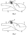
- the knife lever is formed from a first handle 10 and a knife 14 which is interchangeably mounted on it by means of a joint 12, the document lever, on the other hand, consists of a second handle 20 and an anvil 22 carrying the exchangeable base 34.
- a spring 24 is guided in the handle 20 , which engages behind the knife 14 of the knife lever when the scissors are mounted and, when not locked, ensures that the anvil scissors are unlocked the cutting edge 18 of the knife 14 and the surface of the base 34 are offset.
- the knife 14 is mounted by means of the joint 12 and can be replaced after the joint 12 has been pushed out laterally.
- the knife 14 is provided with a notch located next to the joint receiving bore, which engages to secure the knife 14 against rotation in a bolt penetrating the handle
- Set screw 30 is provided, which is guided in the plane of the knife 14 through a threaded bore 16 in the first handle 10.
- This adjusting screw 30 acts on the section of the knife 14 which forms the extension of the cutting edge 18 beyond the joint 12 and forms a stop for the knife 14. Screwing the adjusting screw 30 deeper into the first grip piece 10 brings the cutting edge closer when the scissors are open 18 of the knife 14 on the base 34.
- a reduction in the distance between the handle pieces 10, 20 caused by the regrinding of the knife 14 can thus be compensated for by screwing in the adjusting screw 30.
- the desired distance between the first handle 10 and the second handle 20 when the scissors are closed can be selected within wide limits.
- a arranged between the set screw 30 and the back surface of the knife 14 steel ball 32 serves to reduce the friction.
- the anvil 22 which can also carry an exchangeable base in this exemplary embodiment, is provided - in a manner known per se - with a bow-like section which engages around the handle 20 beyond the pivot point of the anvil 22.
- This bow-like section of the anvil 22 is provided with a threaded bore 16 through which an adjusting screw 30 is guided.
- the set screw 30 is passed through a bore through the second handle and then expanded below such that rotation of the screw in the threaded bore 16 is possible while changing the distance between the bow-like section of the anvil and the second handle 20.
- Fig. 3 shows the anvil cutter shown in Fig. 2, but the set screw 30 is screwed deeper into the threaded bore 16.
- Such readjustment of the adjusting screw 30 can be carried out if the angle formed between the handle pieces 10 and 20 is to be increased, or if the original angle between the handle pieces 10 and 20 is to be restored when the knife 16 is reground.
- the adjusting screw 30 makes it possible to set the individually desired distance between the handle pieces 10, 20 regardless of the wear.
- the adjustability of the distance between the Grips 10, 20 by screwing in or unscrewing the adjusting screw 30 further make it possible to vary the location of the load when the hand is tired due to the constant loading of the same part of the ball of the hand and curvature of the fingers and the resulting lack of blood circulation.
- the actuating device is formed by an adjusting screw, other designs, for example a pivotable eccentric, can also be used as the actuating device.
- anvil scissors enables the cutting edge of the knife to always maintain its relative position to the base received by the anvil when the knife is reground.
Landscapes
- Life Sciences & Earth Sciences (AREA)
- Forests & Forestry (AREA)
- Engineering & Computer Science (AREA)
- Mechanical Engineering (AREA)
- Scissors And Nippers (AREA)
Claims (5)
Priority Applications (1)
| Application Number | Priority Date | Filing Date | Title |
|---|---|---|---|
| AT87113506T ATE50721T1 (de) | 1986-09-17 | 1987-09-15 | Ambossschere. |
Applications Claiming Priority (4)
| Application Number | Priority Date | Filing Date | Title |
|---|---|---|---|
| DE3631554 | 1986-09-17 | ||
| DE19863631554 DE3631554A1 (de) | 1986-09-17 | 1986-09-17 | Ambossschere |
| DE8627305U | 1986-10-07 | ||
| DE19868627305 DE8627305U1 (de) | 1986-10-07 | 1986-10-07 | Amboßschere |
Publications (2)
| Publication Number | Publication Date |
|---|---|
| EP0260669A1 EP0260669A1 (fr) | 1988-03-23 |
| EP0260669B1 true EP0260669B1 (fr) | 1990-03-07 |
Family
ID=25847562
Family Applications (1)
| Application Number | Title | Priority Date | Filing Date |
|---|---|---|---|
| EP87113506A Expired - Lifetime EP0260669B1 (fr) | 1986-09-17 | 1987-09-15 | Cisailles d'enclume |
Country Status (3)
| Country | Link |
|---|---|
| EP (1) | EP0260669B1 (fr) |
| DE (1) | DE3761801D1 (fr) |
| GR (1) | GR3000528T3 (fr) |
Families Citing this family (1)
| Publication number | Priority date | Publication date | Assignee | Title |
|---|---|---|---|---|
| GB0129587D0 (en) * | 2001-12-11 | 2002-01-30 | Univ Sheffield | Hand tool |
Family Cites Families (4)
| Publication number | Priority date | Publication date | Assignee | Title |
|---|---|---|---|---|
| US1959587A (en) * | 1932-04-07 | 1934-05-22 | Oscar L Lawson | Tool |
| US2532359A (en) * | 1945-09-10 | 1950-12-05 | Stipan A Drmic | Pruning shears |
| DE1006031B (de) * | 1955-06-03 | 1957-04-11 | Gerhard Lueers | Vorrichtung zum Abisolieren von elektrischen Leitungen und Kabeln |
| DE2618174A1 (de) * | 1976-04-26 | 1977-11-03 | Artur Martin | Zange |
-
1987
- 1987-09-15 EP EP87113506A patent/EP0260669B1/fr not_active Expired - Lifetime
- 1987-09-15 DE DE8787113506T patent/DE3761801D1/de not_active Expired - Fee Related
-
1990
- 1990-06-05 GR GR90400344T patent/GR3000528T3/el unknown
Also Published As
| Publication number | Publication date |
|---|---|
| GR3000528T3 (en) | 1991-07-31 |
| DE3761801D1 (de) | 1990-04-12 |
| EP0260669A1 (fr) | 1988-03-23 |
Similar Documents
| Publication | Publication Date | Title |
|---|---|---|
| DE69707784T2 (de) | Werkzeug mit variabler Kraft | |
| EP0300544B1 (fr) | Outil de rainurage | |
| EP0116305A1 (fr) | Pince pour tuyaux | |
| DE2735540A1 (de) | Schnell-loesender mechanismus fuer saegeblatt mit hin- und herbewegung | |
| EP0728061A1 (fr) | Ciseaux, notamment ciseaux de coiffeur | |
| CH645013A5 (de) | Osteosynthetische kompressionsplatte. | |
| EP1439929B1 (fr) | Porte-outil pour corps tranchant | |
| EP0666131B1 (fr) | Cisaille à démolir les métaux | |
| EP0085156A2 (fr) | Alésoir à lame unique | |
| DE1652665A1 (de) | Haltevorrichtung fuer Schneidwerkzeuge,insbesondere an Drehbaenken | |
| EP0652816B1 (fr) | Tete porte-lames, en particulier tete porte-lames a profiler | |
| EP0973625B1 (fr) | Dispositif de fixation pour outils | |
| DE7909735U1 (de) | Selbstbohrende Schraube | |
| EP0260669B1 (fr) | Cisailles d'enclume | |
| DE19821924C2 (de) | Gartenschere mit einem Schneidblatt und einem hiermit zusammenwirkenden Amboß | |
| DE1477108A1 (de) | Mit Halter versehener Schnelldrehstahl fuer Spurdrehen | |
| DE20309766U1 (de) | Feststellvorrichtung für die Papierarretierleiste eines Papierschneiders | |
| DE102021101254B3 (de) | Hobel-Vorrichtung mit verstellbarem Messer | |
| DE3631554C2 (fr) | ||
| DE7908055U1 (de) | Fliesenschneidegeraet | |
| EP0033382A2 (fr) | Outil rotatif pour la fabrication de copeaux de bois plats | |
| DE3247073C1 (de) | Preßzange | |
| DE2544877A1 (de) | Werkzeughalter | |
| DE8704161U1 (de) | Medizinisches, insbesondere chirurgisches Instrument | |
| DE808219C (de) | Zange |
Legal Events
| Date | Code | Title | Description |
|---|---|---|---|
| PUAI | Public reference made under article 153(3) epc to a published international application that has entered the european phase |
Free format text: ORIGINAL CODE: 0009012 |
|
| 17P | Request for examination filed |
Effective date: 19880120 |
|
| AK | Designated contracting states |
Kind code of ref document: A1 Designated state(s): AT CH DE GB GR IT LI |
|
| 17Q | First examination report despatched |
Effective date: 19890612 |
|
| GRAA | (expected) grant |
Free format text: ORIGINAL CODE: 0009210 |
|
| AK | Designated contracting states |
Kind code of ref document: B1 Designated state(s): AT CH DE GB GR IT LI |
|
| PG25 | Lapsed in a contracting state [announced via postgrant information from national office to epo] |
Ref country code: GB Effective date: 19900307 |
|
| REF | Corresponds to: |
Ref document number: 50721 Country of ref document: AT Date of ref document: 19900315 Kind code of ref document: T |
|
| REF | Corresponds to: |
Ref document number: 3761801 Country of ref document: DE Date of ref document: 19900412 |
|
| ITF | It: translation for a ep patent filed | ||
| GBV | Gb: ep patent (uk) treated as always having been void in accordance with gb section 77(7)/1977 [no translation filed] | ||
| REG | Reference to a national code |
Ref country code: GR Ref legal event code: FG4A Free format text: 3000528 |
|
| PLBE | No opposition filed within time limit |
Free format text: ORIGINAL CODE: 0009261 |
|
| STAA | Information on the status of an ep patent application or granted ep patent |
Free format text: STATUS: NO OPPOSITION FILED WITHIN TIME LIMIT |
|
| 26N | No opposition filed | ||
| ITTA | It: last paid annual fee | ||
| PGFP | Annual fee paid to national office [announced via postgrant information from national office to epo] |
Ref country code: DE Payment date: 19930716 Year of fee payment: 7 |
|
| PGFP | Annual fee paid to national office [announced via postgrant information from national office to epo] |
Ref country code: GR Payment date: 19930728 Year of fee payment: 7 |
|
| PGFP | Annual fee paid to national office [announced via postgrant information from national office to epo] |
Ref country code: AT Payment date: 19930802 Year of fee payment: 7 |
|
| PGFP | Annual fee paid to national office [announced via postgrant information from national office to epo] |
Ref country code: CH Payment date: 19930902 Year of fee payment: 7 |
|
| PG25 | Lapsed in a contracting state [announced via postgrant information from national office to epo] |
Ref country code: AT Effective date: 19940915 |
|
| PG25 | Lapsed in a contracting state [announced via postgrant information from national office to epo] |
Ref country code: LI Effective date: 19940930 Ref country code: CH Effective date: 19940930 |
|
| PG25 | Lapsed in a contracting state [announced via postgrant information from national office to epo] |
Ref country code: GR Free format text: THE PATENT HAS BEEN ANNULLED BY A DECISION OF A NATIONAL AUTHORITY Effective date: 19950331 |
|
| REG | Reference to a national code |
Ref country code: CH Ref legal event code: PL Ref country code: GR Ref legal event code: MM2A Free format text: 3000528 |
|
| PG25 | Lapsed in a contracting state [announced via postgrant information from national office to epo] |
Ref country code: DE Effective date: 19950601 |
|
| PG25 | Lapsed in a contracting state [announced via postgrant information from national office to epo] |
Ref country code: IT Free format text: LAPSE BECAUSE OF NON-PAYMENT OF DUE FEES;WARNING: LAPSES OF ITALIAN PATENTS WITH EFFECTIVE DATE BEFORE 2007 MAY HAVE OCCURRED AT ANY TIME BEFORE 2007. THE CORRECT EFFECTIVE DATE MAY BE DIFFERENT FROM THE ONE RECORDED. Effective date: 20050915 |