EP0260682A1 - Verfahren zum Aufwickeln von Garn auf Spulen mit zugehöriger Maschine - Google Patents
Verfahren zum Aufwickeln von Garn auf Spulen mit zugehöriger Maschine Download PDFInfo
- Publication number
- EP0260682A1 EP0260682A1 EP87113574A EP87113574A EP0260682A1 EP 0260682 A1 EP0260682 A1 EP 0260682A1 EP 87113574 A EP87113574 A EP 87113574A EP 87113574 A EP87113574 A EP 87113574A EP 0260682 A1 EP0260682 A1 EP 0260682A1
- Authority
- EP
- European Patent Office
- Prior art keywords
- yarn
- winding
- limit value
- bobbin holder
- traversing strokes
- Prior art date
- Legal status (The legal status is an assumption and is not a legal conclusion. Google has not performed a legal analysis and makes no representation as to the accuracy of the status listed.)
- Granted
Links
Images



Classifications
-
- B—PERFORMING OPERATIONS; TRANSPORTING
- B65—CONVEYING; PACKING; STORING; HANDLING THIN OR FILAMENTARY MATERIAL
- B65H—HANDLING THIN OR FILAMENTARY MATERIAL, e.g. SHEETS, WEBS, CABLES
- B65H54/00—Winding, coiling, or depositing filamentary material
- B65H54/02—Winding and traversing material on to reels, bobbins, tubes, or like package cores or formers
- B65H54/38—Arrangements for preventing ribbon winding ; Arrangements for preventing irregular edge forming, e.g. edge raising or yarn falling from the edge
-
- B—PERFORMING OPERATIONS; TRANSPORTING
- B65—CONVEYING; PACKING; STORING; HANDLING THIN OR FILAMENTARY MATERIAL
- B65H—HANDLING THIN OR FILAMENTARY MATERIAL, e.g. SHEETS, WEBS, CABLES
- B65H2701/00—Handled material; Storage means
- B65H2701/30—Handled filamentary material
- B65H2701/31—Textiles threads or artificial strands of filaments
Definitions
- the present invention relates in general to a method of and a machine for winding a continuous yarn or thread on the bobbin, and in particular to an improved method of and machine for winding a continuous yarn or thread on the bobbin which can prevent an occurrence of a so-called ribbonning during the yarn winding operation.
- a winding ratio not so as to have at least an integral number, and upper and lower limit values of a yarn winding angle at which the yarn is wound with respect to a vertical plane perpendicular to an axis of rotation of the bobbin holder; and when the winding ratio reaches a predetermined value, increasing rapidly the number of yarn traversing strokes from the lower limit value of the yarn winding angle to the upper limit value, and decreasing gradually the number of yarn traversing strokes from the upper limit value of the yarn winding angle to the lower limit value with a gradient larger than that of the winding ratio.
- a method of winding a yarn into a yarn package on a bobbin holder comprising the steps of setting a first limit value of a yarn winding angle at which the yarn is wound with respect to a vertical plane perpendicular to an axis of rotation of the bobbin holder, and a traverse stroke of the yarn package; detecting a winding speed of the yarn; calculating a winding ratio and the number of rotations of the the bobbin holder by the first limit value of the yarn winding angle, the traverse stroke and the winding speed of the yarn, a second limit value of the yarn winding angle by the first limit value of the yarn winding angle so that the winding ratio is not within a predetermined width, the number of yarn traversing strokes by the second limit value of the yarn winding angle, the traverse stroke and the winding speed, and a gradient of the number of yarn traversing strokes by the number of yarn traversing strokes and the number of rotations of the bob
- a machine for winding a yarn comprising a bobbin holder on which the yarn is wound into a yarn package; setting means for setting a first limit value of a yarn winding angle at which the yarn is wound with respect to a vertical plane perpendicular to an axis of rotation of the bobbin holder, and a traverse stroke of the yarn package; first detecting means for detecting a winding speed of the yarn; gradient operation means for calculating a winding ratio and the number of rotations of the the bobbin holder by the first limit value of the yarn winding angle, the traverse stroke and the winding speed of the yarn, a second limit value of the yarn winding angle by the first limit value of t he yarn winding angle so that the winding ratio is not within a predetermined width, the number of yarn traversing strokes by the second limit value of the yarn winding angle, the traverse stroke and the winding speed, and a gradient of the number of yarn traversing strokes by
- the yarn In winding a continuous yarn or thread on a bobbin holder at high speeds and forming a yarn package on the bobbin holder, the yarn is generally traversed alternately in opposite directions parallel with the axis of rotation of the bobbin holder at a constant winding angle with respect to a vertical plane perpendicular to an axis of rotation of the bobbin holder.
- a ratio of the number of rotations of the bobbin holder to the number of yarn traversing strokes (hereinafter referred to as a "winding ratio”) is an integral number
- the yarn tends to be wound on a turn of the yarn previously wound on the bobbin, thereby making the outer circumferential surface of the yarn package uneven and forming circumferential rib portions on the yarn package (called “ribbonning”).
- ribbonning Such ribbonning phenomenon may cause the outer circumferential layer of the yarn package to slide to form rib portions or vibration during the yarn winding operation. If the vibration is caused by the ribbonning phenomenon, the yarn tends to be dropped from the layer of the circumferential rib portion formed previous to the rib portion being now formed.
- the number of rotations of the bobbin holder and the number of yarn traversing strokes are detected during the yarn winding operation, and the number of yarn traversing strokes is controlled so that the winding ratio is maintained constant.
- an actual diameter of the yarn package wound on the bobbin holder differs from a yarn package diameter calculated from the number of rotations of the bobbin holder due to the contact pressure applied between the package and the contact roller and due to the rib portions at the axial opposite ends of the package, there are fluctuations of the winding ratio.
- the number of yarn traversing strokes is calculated by detecting the number of rotations of the bobbin holder and multiplying the detected value by the winding ratio, there is a delay of time between the calculation and the operation. Because of the delay of time, even if a winding ratio is set which prevents an occurrence of the ribbonning, the ribbonning will occur if the winding ratio is set in the vicinity of an integral number, 1/2, 1/3, 1/4, and 1/5.
- the yarn is wound with the lower limit value of the number of yarn traversing strokes, and when the winding ratio approaches an integral number, the number of yarn traversing strokes is rapidly increased to the upper limit value and then decreased therefrom in accordance with the winding ratio which prevents an occurrence of ribbonning. Therefore, as in the aforementioned case, the ribbonning occurs due to the delay of time and the difference between the actual package diameter and the calculated package diameter.
- an object of the present invention to prevent an improved method of and machine for winding yarn on a bobbin holder which prevent an occurrence of ribbonning by changing the number of yarn traversing strokes gradually when the upper limit value of the yarn winding angle is changed to the lower limit value of the yarn winding angle.
- a bobbin holder designated by reference numeral 1 has a cylindrical bobbin 2 mounted thereon so that the bobbin 2 rotates therewith.
- the bobbin 2 has a continuous yarn or thread wound thereon into a suitable form of yarn package 3.
- a contact roller 4 rotatable on a shaft 4a.
- the yarn to be wound on the bobbin 2 is fed through a yarn traversing cam 5 which traverses the yarn alternately in opposite directions parallel with the axis of rotation of the bobbin 2 so that the yarn is distributed uniformally throughout the length of the yarn package 3.
- the bobbin holder 1 of the bobbin 2 is connected through a drive shaft 6 to an induction motor 7 so as to be driven for rotation.
- the induction motor 7 rotates with the frequency corresponding to the output of an invertor 8 and drives the bobbin holder 1.
- the yarn traversing cam 5 is connected through a drive shaft 9 to an induction motor 10 so as to be driven for rotation.
- the induction motor 10 rotates with the frequency corresponding to the output of an invertor 11 and drives the yarn traversing cam 5.
- the aforementioned yarn traversing cam 5, drive shaft 9, induction motor 10 and invertor 11 as a whole constitute a traversing mechanism indicated generally by reference numeral 12.
- each of the invertors 8 and 11 is controlled in accordance with a command signal from a controller unit 13 to which signals from first and second electromagnetic pickups 14 and 15 are inputted.
- the first electromagnetic pickup 14 is disposed adjacent a gear 16 fixed on the shaft 4a of the contact roller 4 to detect the number of rotations of the gear 16.
- the number of rotations N c of the contact roller 4 is detected indirectly from the number of rotations of the gear 16.
- the first electromagnetic pickup 14 and gear 16 of the contact roller 4 as a whole constitute first detecting means for detecting a winding speed of the yarn.
- the second electromagnetic pickup 15 is disposed adjacent a gear 18 fixed on the drive shaft 9 of the yarn traversing cam 5 to detect the number of rotations of the gear 18.
- the number of rotations N t of the yarn traversing cam 5 is detected indirectly from the number of rotations of the gear 18.
- the second electromagnetic pickup 15 and gear 18 of the yarn traversing cam 5 as a whole constitute second detecting means 19 for detecting the number of rotations N t of the yarn traversing cam 5.
- a third electromagnetic pickup 27 is disposed adjacent a gear 26 fixed on the drive shaft 6 of the bobbin holder 1 to detect the number of rotations N b of the bobbin holder 1.
- the third electromagnetic pickup 27 and gear 26 of the drive shaft 6 as a whole constitute third detecting means 28 for detecting the number of rotations N b of the bobbin holder 1.
- a setting unit (setting means) 20 which is adapted to set a lower limit value ⁇ L of a yarn winding angle at which the yarn is wound with respect to a vertical plane perpendicular to the axis of rotation of the bobbin 2, a traverse stroke S of the yarn package 3 to be wound on the bobbin 2, a ribbon occurrence width Y and a ribbon occurrence width Z.
- ⁇ L a yarn winding angle at which the yarn is wound with respect to a vertical plane perpendicular to the axis of rotation of the bobbin 2
- a traverse stroke S of the yarn package 3 to be wound on the bobbin 2 a ribbon occurrence width Y and a ribbon occurrence width Z.
- the controller unit 13 has gradient operation means for calculating a gradient of the number of yarn traversing strokes, and traverse operation means for calculating the number of yarn traversing strokes in accordance with the gradient calculated by the gradient operation means.
- the controller unit 13 comprises a central processing unit 21 labelled as "CPU”, a read-only memory 22 labelled as “ROM”, a random access memory 23 labelled as “RAM” and an input-output port 24 labelled as "I/O".
- the CPU 21 receives external data which are necessary for the programs read in the ROM 22, and processes values necessary for a yarn traversing control, giving and receiving data between the CPU 21 and the RAM 23. The processed values are delivered from the CPU 21 to the I/O port 24.
- the I/O port 24 receives signals from the electromagnetic pickups 14, 15 and 27 and a signal from the setting unit 20, and delivers command signals to the invertors 8 and 11 and an indication signal S H to an indicator 25.
- the ROM 22 has stored therein programs and datum which are to be processed in the CPU 21.
- the RAM 23 temporary memorizes external information and data to be used in operation.
- the indicator 25 indicates information necessary for a winding control in accordance with the signal S H delivered from the controller unit 13.
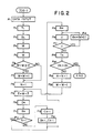
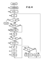
- FIGS. 2 and 4 are flow diagrams for yarn traversing control program.
- the yarn traversing control program according to the present invention consists of a first program indicated by "JOB-1" in FIG. 2 for calculating a locus of the number of yarn traversing strokes which prevents an occurrence of so-called ribbonning phenomenon, and a second program indicated by "JOB-2" in FIG. 4 for calculating the number of yarn traversing strokes during the winding operation.
- the first program JOB-1 and the second program JOB-2 are processed in the recited order.
- a yarn winding speed V, a yarn traverse stroke S, a lower limit value ⁇ L of the yarn winding angle, a ribbon occurrence width Y and a ribbon occurrence width Z are inputted to the setting unit 20. It is desirable that the ribbon occurrence widths Y and Z be between 0.05 and 0.2.
- the number of rotations B L of the bobbin holder 1 is calculated when the yarn package 3 on the bobbin 2 has the maximum diameter.
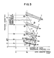
- the winding ratio M calculated at the step P4 is made an integral number W (that is, a winding ratio W2 indicated in FIG. 3 is calculated). In this embodiment, the winding ratio M is made an integral number by omitting fractions.
- the winding ratio M may also be made an integral number by raising to a unit or counting fractions of 0.5 and over as an integral number.
- (M - W) is compared with Z whether the winding ratio M at the point 3 of FIG. 3 is within the ribbon occurrence width Z of the winding ratio W or not.
- the winding ratio M is determined to be not within the ribbon occurrence width Z, and at a step P7 one is added to the winding ratio W obtained at the step P5. That is, the winding ratio W1 is obtained.
- the winding ratio M is determined to be within the ribbon occurrence width Z, and the step P6 advances directly to a step P8 without passing through the step P7. In this embodiment, the aforementioned winding ratio M is not within the ribbon occurrence width Z.
- a step P12 the count value N is compared with one. When the count value N is equal to one, the step P12 advances directly to a step P15 without passing through steps P13 and P14. When the count value N is not equal to one, the step P12 advances to the step P13. Since the count val ue N is one at the step P8, a yarn winding angle ⁇ H is obtained at the step P15 by adding 0.1° to the lower limit value ⁇ L of the yarn winding angle inputted at the step P1.
- the step P18 returns back to the step P16, and as a result, the yarn winding angle ⁇ H is increased 0.1° by 0.1° until the winding ratio u becomes outside the predetermined width between (W1 + Z) and (W1 - Y).
- the step P17 advances to a step P19.
- the diameter D N of the bobbin is compared with the maximum diameter D H of the winding machine. Since the count value N is one, the diameter D1 of the bobbin at the point 2 of FIG. 3 is compared with the maximum diameter D H of the winding machine.
- the diameter D N is less than the maximum diameter D H , one is added to the count value N at a step P21.
- a step P22 one is subtracted from the winding ratio W obtained at the step P5.
- the step P22 returns back to the step P9 to calculate a winding ratio E of the point 4 indicated in FIG. 3 by adding the ribbon occurrence width Z to the winding ratio W1.
- a package diameter D2 of the point 3 is calculated in accordance with the aforementioned equation (3).
- the number of rotations B2 of the bobbin holder 1 is calculated in accordance with the aforementioned equation (4).
- the count value N is compared with one.
- a descending gradient C1 between the points 2 and 4 of FIG. 3 is calculated at the step P13 in accordance with the following equation (8);
- C N-1 (T N-1 - T L ) / (B N-1 - B N ) --- (8), wherein the C N-1 indicates a descending gradient, the T L indicates a lower limit value of the number of yarn traversing strokes, the B N-1 indicates the number of rotations of the bobbin holder calculated last time, the T N-1 indicates the number of yarn traversing strokes calculated last time and the B N indicates the number of rotations of the bobbin holder calculated this time.
- the B N-1 and the C N-1 are memorized in the RAM 23.
- the B1 and C1 are memorized in the RAM 23.
- a yarn winding angle ⁇ H is obtained by adding 0.1° to the lower limit value ⁇ L of the yarn winding angle.
- a winding ratio u when the yarn winding angle is ⁇ H is calculated in accordance with the aforementioned equation (5).
- the steps P17, P18 and P16 are repeated, and when the winding ratio u is n ot between (W N + Z) and (W N - Y), the number of yarn traversing strokes T2 when the yarn winding angle of the point 5 of FIG. 3 is ⁇ H is calculated at the step P19 in accordance with the aforementioned equation (7).
- the number of yarn traversing strokes T N and the gradient C N-1 at the points 6, 7, 8, 9 and 10 of FIG. 3 are calculated by repeating the aforementioned steps P9 through P22.
- the diameter D N is more than the maximum diameter D H , the aforementioned first program JOB-1 ends and then the second program JOB-2 starts.
- the bobbin holder 1 and the traversing mechanism 12 are actuated by a command of actuation of the winding machine, and when the number of yarn traversing strokes reaches a predetermined value (in this embodiment, a lower limit value T L ), the second program JOB-2 shown in FIG. 4 starts at a step P31 by a command of operation.
- the number of rotations B of the bobbin holder 1 is picked up every a predetermined cycle, and at a step P34, the number of rotations B is compared with the number of rotations B L when the diameter of the package 3 on the bobbin 2 is the maximum D H . While data have been read out in accordance with the number of rotations B of the bobbin holder 1, it is noted that they may also be read out in accordance with the diameter of the yarn package 3 on the bobbin 2.
- the number of rotations B of the bobbin holder 1 picked up at the step P33 is compared at a step P35 with the number of rotations B N of the bobbin holder 1 calculated in the first program JOB-1.
- the B N+1 and C N calculated and memorized in the first program JOB-1 are read out at a step P36.
- the step P35 advances directly to a step P37 without passing through the step P36.
- the step P38 advances to a step P40 without passing through the step P39.
- a reference value T is calculated in accordance with the following equation (10).
- T K (T0 + dT) --- --- (10), wherein the T indicates a reference value for comparing with the number of yarn traversing strokes detected at the pickup 15, the K indicates a constant determined by the number of turns of the cam, the number of teeth of the gear 8, etc., the T0 indicates the number of yarn traversing strokes calculated at the step P37, and the dT indicates a value for increasing and decreasing the number of yarn traversing strokes by a predetermined amount with a predetermined cycle.
- the reference value T is compared with the number of yarn traversing strokes detected at the pickup 15, and according to the difference between the two, the frequency of the invertor 11, which supples electric power to the motor 10, is controlled by a so-called PID control.
- the value G is compared with a value J inputted in advan ce. When the value G is not equal to the value J, one is added to the value G at a step P44, and the step P44 returns back to the step P33.
- the second program JOB-2 ends. If the aforementioned each step is processed repeatedly, the number of yarn traversing strokes can be obtained which varies with an amplitude of (K ⁇ dT) and a cycle of t as shown in FIG. 6. The magnitude of the amplitude (K ⁇ dT) is determined by the magnitude of the data dT, and the magnitude of the cycle t is determined by the magnitude of the value J.
- the amplitude (K ⁇ dT) be between 0.5% and 8% of the T L and that the cycle t be between 0.5 sec. and 4 sec. While the pattern of dT has been shown in FIG. 5, it is noted that the patterns as shown in FIGS. 7 and 8 may also be used in accordance with operating conditions.
- the yarn winding angle is gradually increased very little by very little, the difference between the upper and lower limit values of the yarn winding angle can be made small, and therefore, the irregularities of the lateral end faces of the packages can be made small.
- the effect of the present invention can also be achieved.
- the effect of the present invention can be achieved by a locus of the number of yarn traversing strokes as shown in FIG. 10 and a locus of the number of yarn traversing strokes as shown in FIG. 11.
- the upper and lower limit values of the winding ratio are inputted in advance, and the number of yarn traversing strokes is decreased between the upper and lower limit values with a predetermined gradient larger than that of the winding ratio.
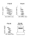
- the lower limit value ⁇ L of the number of yarn traversing strokes is constant, it is noted that the upper limit value may be constant and the lower limit value varied as shown in FIG. 12 or each of the upper and lower limit values varied. It is also noted that the lower or upper limit values of the number of yarn traversing strokes may be decreased on the way as shown in Figs. 13, 14 and 15.
- the motor 10 has been an induction motor and the number of rotations thereof picked up and fed back, it is noted that the motor 10 may also be an induction motor without a feedback control if the values of ribbon occurrence widths are slightly increased. Also, the motor 10 may be a synchronous motor without a feedback control.
Landscapes
- Engineering & Computer Science (AREA)
- Textile Engineering (AREA)
- Winding Filamentary Materials (AREA)
Applications Claiming Priority (2)
| Application Number | Priority Date | Filing Date | Title |
|---|---|---|---|
| JP22119686 | 1986-09-18 | ||
| JP221196/86 | 1986-09-18 |
Publications (2)
| Publication Number | Publication Date |
|---|---|
| EP0260682A1 true EP0260682A1 (de) | 1988-03-23 |
| EP0260682B1 EP0260682B1 (de) | 1991-04-03 |
Family
ID=16762974
Family Applications (1)
| Application Number | Title | Priority Date | Filing Date |
|---|---|---|---|
| EP87113574A Expired EP0260682B1 (de) | 1986-09-18 | 1987-09-16 | Verfahren zum Aufwickeln von Garn auf Spulen mit zugehöriger Maschine |
Country Status (4)
| Country | Link |
|---|---|
| US (1) | US4779813A (de) |
| EP (1) | EP0260682B1 (de) |
| JP (1) | JPH0725479B2 (de) |
| DE (1) | DE3769053D1 (de) |
Cited By (3)
| Publication number | Priority date | Publication date | Assignee | Title |
|---|---|---|---|---|
| EP0375043A1 (de) * | 1988-12-23 | 1990-06-27 | SAVIO S.p.A. | Verfahren zum Kontrollieren der Fadenführung auf einem Wickel in einer Aufspulvorrichtung für synthetische Fäden |
| US5639037A (en) * | 1993-06-25 | 1997-06-17 | Savio Macchine Tessili S.R.L. | Method and apparatus for distributing wound yarn on a bobbin driven by a grooved roller |
| EP2060525A4 (de) * | 2006-09-06 | 2011-01-12 | Mitsubishi Rayon Co | Kohlefaserwickel und herstellungsverfahren dafür |
Families Citing this family (11)
| Publication number | Priority date | Publication date | Assignee | Title |
|---|---|---|---|---|
| DE3918846A1 (de) * | 1989-06-09 | 1990-12-13 | Maag Fritjof | Praezisionskreuzspule, verfahren zu deren herstellung und spuleinrichtung dafuer |
| JPH03223069A (ja) * | 1990-01-25 | 1991-10-02 | Toray Eng Co Ltd | 巻取機の駆動制御方法 |
| IT1251866B (it) * | 1991-09-24 | 1995-05-26 | Fadis Spa | Metodo per il controllo della posizione del punto di inversione del filato particolarmente per macchine roccatrici e relativa apparecchiatura |
| DE4208395A1 (de) * | 1992-03-16 | 1993-09-23 | Sahm Georg Fa | Verfahren zum aufspulen von einer spuleinrichtung zugefuehrtem, band- oder fadenfoermigem spulgut in kreuzspulung mit praezisionswicklung |
| DE4223271C1 (de) * | 1992-07-17 | 1993-06-24 | Neumag - Neumuenstersche Maschinen- Und Anlagenbau Gmbh, 2350 Neumuenster, De | |
| CH691474A5 (de) * | 1992-11-13 | 2001-07-31 | Rieter Ag Maschf | Verfahren und Vorrichtung zum Aufspulen eines Fadens. |
| KR100310963B1 (ko) * | 1993-08-14 | 2001-12-28 | 이.파우. 뢰르허 | 사를크로스와인드보빈으로감는방법 |
| US5727744A (en) * | 1996-03-13 | 1998-03-17 | Threlkeld; James O. | Method and apparatus to control the winding pattern on a yarn package |
| US6311920B1 (en) * | 1997-02-05 | 2001-11-06 | Tb Wood's Enterprises, Inc. | Precision winding method and apparatus |
| US6568623B1 (en) | 2000-03-21 | 2003-05-27 | Owens-Corning Fiberglas Technology, Inc. | Method for controlling wind angle and waywind during strand package buildup |
| JP4711103B2 (ja) * | 2003-03-28 | 2011-06-29 | 村田機械株式会社 | 糸の巻き取り方法とその装置 |
Citations (4)
| Publication number | Priority date | Publication date | Assignee | Title |
|---|---|---|---|---|
| US3741491A (en) * | 1971-11-29 | 1973-06-26 | Leesona Corp | Apparatus for winding yarn |
| US4049211A (en) * | 1975-11-05 | 1977-09-20 | Rieter Machine Works, Ltd. | Winding apparatus for textile threads |
| EP0064579A1 (de) * | 1981-05-08 | 1982-11-17 | Toray Industries, Inc. | Fadenaufwickelvorrichtung |
| DE3219880A1 (de) * | 1982-05-27 | 1984-02-16 | Barmag Barmer Maschinenfabrik Ag, 5630 Remscheid | Verfahren zur spiegelstoerung beim aufwickeln eines fadens in wilder wicklung |
Family Cites Families (10)
| Publication number | Priority date | Publication date | Assignee | Title |
|---|---|---|---|---|
| JPS5733264A (en) * | 1980-08-01 | 1982-02-23 | Iseki & Co Ltd | Input shaft bearing retainer in transmission mechanism |
| DE3210244A1 (de) * | 1982-03-20 | 1983-09-22 | Barmag Barmer Maschinenfabrik Ag, 5630 Remscheid | Verfahren zur spiegelstoerung beim aufwickeln eines fadens in wilder wicklung |
| US4504021A (en) * | 1982-03-20 | 1985-03-12 | Barmag Barmer Maschinenfabrik Ag | Ribbon free wound yarn package and method and apparatus for producing the same |
| US4504024A (en) * | 1982-05-11 | 1985-03-12 | Barmag Barmer Maschinenfabrik Ag | Method and apparatus for producing ribbon free wound yarn package |
| CH659055A5 (de) * | 1982-09-27 | 1986-12-31 | Schweiter Ag Maschf | Kreuzspulmaschine zum herstellen der wicklung einer kreuzspule. |
| DE3401530A1 (de) * | 1984-01-18 | 1985-07-25 | Fritjof Dipl.-Ing. Dr.-Ing. 6233 Kelkheim Maag | Praezisionsspule, sowie verfahren und vorrichtung zu deren herstellung |
| DE3562216D1 (en) * | 1984-08-18 | 1988-05-26 | Barmag Barmer Maschf | Cylindrical cross-wound bobbin |
| CN1005029B (zh) * | 1985-03-05 | 1989-08-23 | 巴马格·巴默机器制造股份公司 | 卷绕方法 |
| EP0195325B1 (de) * | 1985-03-11 | 1988-09-07 | B a r m a g AG | Aufwickelverfahren |
| DE3521152C2 (de) * | 1985-06-13 | 1996-05-30 | Schlafhorst & Co W | Verfahren und Vorrichtung zum Vermeiden von Bildwicklungen beim Wickeln einer Kreuzspule |
-
1987
- 1987-09-16 EP EP87113574A patent/EP0260682B1/de not_active Expired
- 1987-09-16 DE DE8787113574T patent/DE3769053D1/de not_active Expired - Lifetime
- 1987-09-17 JP JP23465787A patent/JPH0725479B2/ja not_active Expired - Fee Related
- 1987-09-17 US US07/098,045 patent/US4779813A/en not_active Expired - Lifetime
Patent Citations (4)
| Publication number | Priority date | Publication date | Assignee | Title |
|---|---|---|---|---|
| US3741491A (en) * | 1971-11-29 | 1973-06-26 | Leesona Corp | Apparatus for winding yarn |
| US4049211A (en) * | 1975-11-05 | 1977-09-20 | Rieter Machine Works, Ltd. | Winding apparatus for textile threads |
| EP0064579A1 (de) * | 1981-05-08 | 1982-11-17 | Toray Industries, Inc. | Fadenaufwickelvorrichtung |
| DE3219880A1 (de) * | 1982-05-27 | 1984-02-16 | Barmag Barmer Maschinenfabrik Ag, 5630 Remscheid | Verfahren zur spiegelstoerung beim aufwickeln eines fadens in wilder wicklung |
Cited By (5)
| Publication number | Priority date | Publication date | Assignee | Title |
|---|---|---|---|---|
| EP0375043A1 (de) * | 1988-12-23 | 1990-06-27 | SAVIO S.p.A. | Verfahren zum Kontrollieren der Fadenführung auf einem Wickel in einer Aufspulvorrichtung für synthetische Fäden |
| US5056724A (en) * | 1988-12-23 | 1991-10-15 | Savio S.P.A. | Process and apparatus for controlling distribution of thread on a package in a collection unit for synthetic threads |
| US5639037A (en) * | 1993-06-25 | 1997-06-17 | Savio Macchine Tessili S.R.L. | Method and apparatus for distributing wound yarn on a bobbin driven by a grooved roller |
| EP2060525A4 (de) * | 2006-09-06 | 2011-01-12 | Mitsubishi Rayon Co | Kohlefaserwickel und herstellungsverfahren dafür |
| CN101511715B (zh) * | 2006-09-06 | 2012-06-06 | 三菱丽阳株式会社 | 碳纤维卷装以及其制造方法 |
Also Published As
| Publication number | Publication date |
|---|---|
| DE3769053D1 (de) | 1991-05-08 |
| JPH0725479B2 (ja) | 1995-03-22 |
| JPS63185779A (ja) | 1988-08-01 |
| EP0260682B1 (de) | 1991-04-03 |
| US4779813A (en) | 1988-10-25 |
Similar Documents
| Publication | Publication Date | Title |
|---|---|---|
| EP0260682B1 (de) | Verfahren zum Aufwickeln von Garn auf Spulen mit zugehöriger Maschine | |
| EP0248406B1 (de) | Überführungsapparat für Faden | |
| US6065712A (en) | Method and apparatus for winding a yarn into a package | |
| EP0375043B1 (de) | Verfahren zum Kontrollieren der Fadenführung auf einem Wickel in einer Aufspulvorrichtung für synthetische Fäden | |
| US4504021A (en) | Ribbon free wound yarn package and method and apparatus for producing the same | |
| US4504024A (en) | Method and apparatus for producing ribbon free wound yarn package | |
| US4325517A (en) | Method and apparatus for winding textile yarns | |
| US4697753A (en) | Stepped precision winding process | |
| EP0630846B1 (de) | Verfahren und Vorrichtung zur Fadenverlegung auf einer Spule mit einer genuteten Antriebswalze | |
| US4771960A (en) | Method for winding a cross-wound package | |
| US4798347A (en) | Method for winding filament yarns | |
| CN100480157C (zh) | 纱的卷绕方法及其装置 | |
| JP3285405B2 (ja) | ワインダーに導入されるテープ状または糸状の巻体を精密巻を有するチーズ巻にして巻取る方法とその装置 | |
| EP0470273B1 (de) | Verfahren und Vorrichtung zum Aufspulen eines Garnes | |
| US20020043585A1 (en) | Method and apparatus for winding a continuously advancing yarn | |
| US20020033428A1 (en) | Method and apparatus for winding a yarn package | |
| CN1082486C (zh) | 筒子的生产方法和装置 | |
| DE3818360C2 (de) | ||
| US5725164A (en) | Method of winding a ribbon free yarn package | |
| US6308907B1 (en) | Method for winding up a thread | |
| US5727744A (en) | Method and apparatus to control the winding pattern on a yarn package | |
| JPH06200428A (ja) | ワインダーに導入される糸状の巻取品を段付き精密チーズ巻にして一定速度で連続的に巻き取る方法とこの方法を実行するワインダー | |
| JPH0372545B2 (de) | ||
| JP2646727B2 (ja) | 糸条の巻取装置 | |
| JP4225589B2 (ja) | あらいピッチで巻かれた綾巻ボビンを製作する方法と装置 |
Legal Events
| Date | Code | Title | Description |
|---|---|---|---|
| PUAI | Public reference made under article 153(3) epc to a published international application that has entered the european phase |
Free format text: ORIGINAL CODE: 0009012 |
|
| AK | Designated contracting states |
Kind code of ref document: A1 Designated state(s): CH DE IT LI |
|
| 17P | Request for examination filed |
Effective date: 19880622 |
|
| 17Q | First examination report despatched |
Effective date: 19891201 |
|
| GRAA | (expected) grant |
Free format text: ORIGINAL CODE: 0009210 |
|
| AK | Designated contracting states |
Kind code of ref document: B1 Designated state(s): CH DE IT LI |
|
| REF | Corresponds to: |
Ref document number: 3769053 Country of ref document: DE Date of ref document: 19910508 |
|
| ITF | It: translation for a ep patent filed | ||
| PLBE | No opposition filed within time limit |
Free format text: ORIGINAL CODE: 0009261 |
|
| STAA | Information on the status of an ep patent application or granted ep patent |
Free format text: STATUS: NO OPPOSITION FILED WITHIN TIME LIMIT |
|
| 26N | No opposition filed | ||
| PGFP | Annual fee paid to national office [announced via postgrant information from national office to epo] |
Ref country code: DE Payment date: 20000911 Year of fee payment: 14 |
|
| PGFP | Annual fee paid to national office [announced via postgrant information from national office to epo] |
Ref country code: CH Payment date: 20000922 Year of fee payment: 14 |
|
| PG25 | Lapsed in a contracting state [announced via postgrant information from national office to epo] |
Ref country code: LI Free format text: LAPSE BECAUSE OF NON-PAYMENT OF DUE FEES Effective date: 20010930 Ref country code: CH Free format text: LAPSE BECAUSE OF NON-PAYMENT OF DUE FEES Effective date: 20010930 |
|
| PG25 | Lapsed in a contracting state [announced via postgrant information from national office to epo] |
Ref country code: DE Free format text: LAPSE BECAUSE OF NON-PAYMENT OF DUE FEES Effective date: 20020501 |
|
| REG | Reference to a national code |
Ref country code: CH Ref legal event code: PL |
|
| PG25 | Lapsed in a contracting state [announced via postgrant information from national office to epo] |
Ref country code: IT Free format text: LAPSE BECAUSE OF NON-PAYMENT OF DUE FEES Effective date: 20050916 |