EP0260690A2 - Equipment de surveillance - Google Patents
Equipment de surveillance Download PDFInfo
- Publication number
- EP0260690A2 EP0260690A2 EP87113607A EP87113607A EP0260690A2 EP 0260690 A2 EP0260690 A2 EP 0260690A2 EP 87113607 A EP87113607 A EP 87113607A EP 87113607 A EP87113607 A EP 87113607A EP 0260690 A2 EP0260690 A2 EP 0260690A2
- Authority
- EP
- European Patent Office
- Prior art keywords
- liquid
- measuring device
- sensor
- potential
- electrolytic
- Prior art date
- Legal status (The legal status is an assumption and is not a legal conclusion. Google has not performed a legal analysis and makes no representation as to the accuracy of the status listed.)
- Granted
Links
Images

Classifications
-
- G—PHYSICS
- G01—MEASURING; TESTING
- G01F—MEASURING VOLUME, VOLUME FLOW, MASS FLOW OR LIQUID LEVEL; METERING BY VOLUME
- G01F1/00—Measuring the volume flow or mass flow of fluid or fluent solid material wherein the fluid passes through a meter in a continuous flow
- G01F1/56—Measuring the volume flow or mass flow of fluid or fluent solid material wherein the fluid passes through a meter in a continuous flow by using electric or magnetic effects
- G01F1/64—Measuring the volume flow or mass flow of fluid or fluent solid material wherein the fluid passes through a meter in a continuous flow by using electric or magnetic effects by measuring electrical currents passing through the fluid flow; measuring electrical potential generated by the fluid flow, e.g. by electrochemical, contact or friction effects
-
- G—PHYSICS
- G01—MEASURING; TESTING
- G01L—MEASURING FORCE, STRESS, TORQUE, WORK, MECHANICAL POWER, MECHANICAL EFFICIENCY, OR FLUID PRESSURE
- G01L19/00—Details of, or accessories for, apparatus for measuring steady or quasi-steady pressure of a fluent medium insofar as such details or accessories are not special to particular types of pressure gauges
- G01L19/08—Means for indicating or recording, e.g. for remote indication
- G01L19/083—Means for indicating or recording, e.g. for remote indication electrical
Definitions
- the invention relates to a device for measuring the operating pressure of an electrolytic liquid flowing out of a line.
- pressure monitors in the form of pressure switches are often used, which are connected to the pressure medium supply line and by means of which the pressure medium supply is interrupted as soon as the pressure drops below an adjustable pressure level, for example.
- pressure switches have proven themselves, they cannot be used when monitoring the operating pressure of a liquid enriched with nutrients, since the movable components of the expensive pressure switches stick to the settling substance particles after a short time and thus their functionality to a considerable extent is affected.
- the object of the invention is therefore to provide a device for measuring the operating pressure of an electrolytic liquid flowing out of a line create, by means of which in particular the minimum pressure of a liquid enriched with nutrients can be monitored in an extremely simple but reliable manner.
- the construction effort required for this should be kept low, but nevertheless a safe and trouble-free function should always be guaranteed.
- a liquid sensor is arranged in the jet region of the liquid flowing out of the supply line, which is connected to a first potential, for example a current source, and a control device for evaluating the signals produced when the liquid sensor is acted upon by the liquid jet, and that the supply line of the liquid is connected to a second potential, preferably to ground.
- liquid sensor vertically and / or horizontally adjustable relative to the liquid supply line, which can be suspended by means of a deformable rotating bracket or the like.
- a mixture formed from the electrolytic liquid and one or more of these additives for example a feed prepared in an automatic feeder
- the receptacle of the electrolytic liquid can be provided with a further, preferably height-adjustable, liquid sensor connected to the control device, by means of which, depending on the liquid level in the receptacle, the liquid supply line, e.g. can be closed or opened for an adjustable period of time.
- the two liquid sensors should expediently be arranged with a preferably adjustable lateral distance from one another in the region of the liquid jet.
- the signals of the two liquid sensors can be evaluated alternately by means of the control device, but it is also possible to connect the two liquid sensors to different potentials or together to one potential and to connect the supply line of the electrolytic liquid to another potential.
- the measuring device designed according to the invention it is possible in a very simple manner to determine whether an electrolytic liquid flowing out of a line has the predetermined operating pressure or whether it has dropped below a predetermined value. If a liquid sensor that is connected to a first potential and a control device is arranged in the jet of the outflowing liquid and the liquid line is connected to a second potential, then by means of of the liquid jet, the circuit is closed, so that a signal is present when the liquid sensor is acted upon by the liquid jet. And this evaluable signal thus indicates that the liquid jet exits the liquid line at a predetermined pressure which corresponds to the operating pressure. If, on the other hand, the operating pressure drops below the value that can be set by the position of the liquid sensor, this is no longer applied; an associated device, for example a metering device, can then be switched off immediately.
- the measuring device according to the invention thus enables reliable determination of the pressure level of an outflowing liquid with simple handling and can be used to avoid uncontrolled mixing ratios in an advantageous manner, in particular in the preparation of liquid animal feed in automatic feeders.
- the device shown in FIG. 1 and designated 1 serves to measure the operating pressure of an electrolytic liquid flowing out of a supply line 2 in order to actuate or shut down a mixture and / or another device depending on the operating pressure of the liquid.
- a liquid sensor 11 is arranged in the area of the liquid jet 3 emerging from the feed line 2, which is suspended by means of a flexible wire bracket 11 'on a horizontally and vertically adjustable holder 12, as is illustrated by the arrows 17 and 18 shown. Via a control line 14, in which an amplifier 15 is inserted, the liquid sensor 11 is connected to a control unit 13, from which control signals 16 and / or 16 ⁇ can be taken.
- the liquid sensor 11 is thus connected to a current-carrying first potential, the supply line 2 via a current line 5 to a ground 4 as the second potential, so that when the electrolytic liquid flows out with a minimum pressure, which corresponds to the operating pressure, the liquid sensor 11, the position of which is adjustable, is applied to a receptacle 10. A circuit is thus closed by this and the feed line 2 via the electrolytic liquid. If, on the other hand, the pressure of the outflowing liquid drops in such a way that the liquid sensor 11 is no longer acted upon by the liquid jet 3, the liquid sensor 11 must of course be arranged in the area of the liquid jet 3 in such a way that it is acted upon at a selected pressure level of the control device 13 and a machine assigned to the device 1 can be switched accordingly.
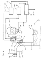
- the device 21 according to FIG. 2 is assigned to an automatic feeder designated by 30, in which a feed is prepared from an electrolytic liquid supplied via a line 22 and a powder which is stored in a storage container 37.
- a liquid sensor 31 is in turn suspended by means of a wire bracket 31 ⁇ which is attached to a holder 32. As is indicated by arrow 46, this is horizontally adjustable.
- the wire bracket 31 ⁇ is adjustable in height by means of a slot 44, so that the liquid sensor 31 can be aligned with the liquid jet 23 without difficulty.
- the liquid sensor 31 Via a line 34, into which an amplifier 35 is inserted, the liquid sensor 31 is connected to a control unit 33, which is connected via a line 36 is connected to a shut-off valve 38 installed in the storage container 37 and via a further line 39 to a shut-off valve 26 inserted into the line 22.
- the liquid sensor 31 is also connected to a current source and thus to a first potential via the line 34 in this exemplary embodiment, while the supply line 22 is connected to a ground 24 via a line 25 and thus forms the second potential, so that when the liquid sensor is acted upon 31 the operating pressure of the liquid can be determined by the liquid jet flowing out of the feed line 22.
- the shut-off valve 38 is actuated via the control unit 33.
- the supply of powder from the storage container 37 is thereby prevented, an uncontrolled composition of the feed to be processed is thus avoided.
- a further horizontally and by means of a slot 45 also vertically adjustable suspended liquid sensor 41 is provided, which is also arranged in the region of the liquid jet 23 and is connected to the control unit 33 via a line 42 provided with an amplifier 43.
- the liquid sensor 41 projects into the automatic feeder 30 so that the liquid level 40 can be determined therein. As soon as this drops below the liquid sensor 41, the automatic feeder 30 is put into operation.
- both liquid sensors 21 and 41 can be connected to different potentials, but it is also possible to connect them together to one potential and the supply line 22 to another potential in order to obtain a circuit.
- the supply of the powder from the storage container 37 is also interrupted with the aid of the control device 33, so that uncontrollable mixtures are reliably avoided.
Landscapes
- Physics & Mathematics (AREA)
- General Physics & Mathematics (AREA)
- Chemical & Material Sciences (AREA)
- Chemical Kinetics & Catalysis (AREA)
- Electrochemistry (AREA)
- Fluid Mechanics (AREA)
- Measuring Fluid Pressure (AREA)
- Jet Pumps And Other Pumps (AREA)
- Apparatus Associated With Microorganisms And Enzymes (AREA)
- Water Treatment By Electricity Or Magnetism (AREA)
- Measuring Pulse, Heart Rate, Blood Pressure Or Blood Flow (AREA)
- Eye Examination Apparatus (AREA)
- Catching Or Destruction (AREA)
- Measurement Of The Respiration, Hearing Ability, Form, And Blood Characteristics Of Living Organisms (AREA)
Priority Applications (1)
| Application Number | Priority Date | Filing Date | Title |
|---|---|---|---|
| AT87113607T ATE75311T1 (de) | 1986-09-19 | 1987-09-17 | Ueberwachungseinrichtung. |
Applications Claiming Priority (2)
| Application Number | Priority Date | Filing Date | Title |
|---|---|---|---|
| DE19863631908 DE3631908A1 (de) | 1986-09-19 | 1986-09-19 | Messeinrichtung |
| DE3631908 | 1986-09-19 |
Publications (3)
| Publication Number | Publication Date |
|---|---|
| EP0260690A2 true EP0260690A2 (fr) | 1988-03-23 |
| EP0260690A3 EP0260690A3 (en) | 1989-08-09 |
| EP0260690B1 EP0260690B1 (fr) | 1992-04-22 |
Family
ID=6309937
Family Applications (1)
| Application Number | Title | Priority Date | Filing Date |
|---|---|---|---|
| EP87113607A Expired - Lifetime EP0260690B1 (fr) | 1986-09-19 | 1987-09-17 | Equipment de surveillance |
Country Status (4)
| Country | Link |
|---|---|
| EP (1) | EP0260690B1 (fr) |
| AT (1) | ATE75311T1 (fr) |
| CH (1) | CH665288A5 (fr) |
| DE (2) | DE3631908A1 (fr) |
Family Cites Families (1)
| Publication number | Priority date | Publication date | Assignee | Title |
|---|---|---|---|---|
| CH650590A5 (fr) * | 1982-04-16 | 1985-07-31 | Gerard Andre Lavanchy | Procede et dispositif de mesure du debit ou de la qualite granulometrique d'un materiau pulverulent. |
-
1986
- 1986-09-19 DE DE19863631908 patent/DE3631908A1/de not_active Withdrawn
-
1987
- 1987-03-27 CH CH1195/87A patent/CH665288A5/de not_active IP Right Cessation
- 1987-09-17 AT AT87113607T patent/ATE75311T1/de not_active IP Right Cessation
- 1987-09-17 EP EP87113607A patent/EP0260690B1/fr not_active Expired - Lifetime
- 1987-09-17 DE DE8787113607T patent/DE3778464D1/de not_active Expired - Fee Related
Also Published As
| Publication number | Publication date |
|---|---|
| ATE75311T1 (de) | 1992-05-15 |
| CH665288A5 (de) | 1988-04-29 |
| EP0260690A3 (en) | 1989-08-09 |
| EP0260690B1 (fr) | 1992-04-22 |
| DE3631908A1 (de) | 1988-03-31 |
| DE3778464D1 (de) | 1992-05-27 |
Similar Documents
| Publication | Publication Date | Title |
|---|---|---|
| EP0654660B1 (fr) | Procédé et appareil de détection du changement de viscosité dans un fluide agité par un agitateur magnétique | |
| DE3220068C2 (fr) | ||
| DE69201809T2 (de) | Bewegungsdetektionsschaltung für ein Magnetventil. | |
| DE60206284T2 (de) | Vorrichtung und verfahren zur steuerung der klemmkraft eines mischbehälters in einem flüssigkeitsmischer | |
| DE3714924C2 (fr) | ||
| DE3715591A1 (de) | Einrichtung und verfahren zur ueberwachung des schaltzustandes von magnetventilen bei elektrohydraulischen ausbausteuerungen u.dgl. | |
| CH691476A5 (de) | Vorrichtung zum Füllen einer Kanne mit Faserband. | |
| DE1947566C3 (de) | Vorrichtung zum Aufbereiten von Formsanden in einer Mischtrommel | |
| DE69024548T2 (de) | Füllapparatur | |
| DE69628854T2 (de) | Fadenspannungssignalgeber | |
| EP0260690B1 (fr) | Equipment de surveillance | |
| EP0121599A2 (fr) | Procédé et dispositif pour le transport pneumatique des particules fines | |
| DE2620686A1 (de) | Einrichtung zum automatischen fuettern von tieren mit nassfutter | |
| DE1923662C3 (de) | Elektronisches LängenmeBgerät | |
| DE69101977T2 (de) | Vorrichtung zur Ausstreuung eines körnigen Materials. | |
| DE3321716C2 (fr) | ||
| EP1135293A1 (fr) | Procede et dispositif pour remplir des futs | |
| DE69710969T2 (de) | Streuer | |
| DE2023495C3 (de) | Vorrichtung zum Fördern von Feststoffen | |
| DE9113543U1 (de) | Fallkörper-Viskosimeter | |
| EP0166265A1 (fr) | Procédé et dispositif pour le transport dosable et pneumatique de matières en vrac d'un réservoir sous pression | |
| DE10065094A1 (de) | Wägevorrichtung mit Freistellungseinrichtung | |
| DD230929A1 (de) | Vorrichtung zur kontinuierlichen mengenmessung von fluessigen und koernigen medien | |
| DE2223614C3 (de) | Elektronische Einrichtung zum Prüfen und Einstellen der Funktionen eines elektronischen Fadenreinigers | |
| DD160243A3 (de) | Messeinrichtung zur ermittlung von deformationswerten |
Legal Events
| Date | Code | Title | Description |
|---|---|---|---|
| PUAI | Public reference made under article 153(3) epc to a published international application that has entered the european phase |
Free format text: ORIGINAL CODE: 0009012 |
|
| AK | Designated contracting states |
Kind code of ref document: A2 Designated state(s): AT BE DE ES FR GB IT NL SE |
|
| PUAL | Search report despatched |
Free format text: ORIGINAL CODE: 0009013 |
|
| AK | Designated contracting states |
Kind code of ref document: A3 Designated state(s): AT BE DE ES FR GB IT NL SE |
|
| 17P | Request for examination filed |
Effective date: 19900203 |
|
| 17Q | First examination report despatched |
Effective date: 19910426 |
|
| GRAA | (expected) grant |
Free format text: ORIGINAL CODE: 0009210 |
|
| AK | Designated contracting states |
Kind code of ref document: B1 Designated state(s): AT BE DE ES FR GB IT NL SE |
|
| PG25 | Lapsed in a contracting state [announced via postgrant information from national office to epo] |
Ref country code: BE Effective date: 19920422 |
|
| REF | Corresponds to: |
Ref document number: 75311 Country of ref document: AT Date of ref document: 19920515 Kind code of ref document: T |
|
| REF | Corresponds to: |
Ref document number: 3778464 Country of ref document: DE Date of ref document: 19920527 |
|
| ITF | It: translation for a ep patent filed | ||
| GBT | Gb: translation of ep patent filed (gb section 77(6)(a)/1977) | ||
| PG25 | Lapsed in a contracting state [announced via postgrant information from national office to epo] |
Ref country code: ES Free format text: LAPSE BECAUSE OF FAILURE TO SUBMIT A TRANSLATION OF THE DESCRIPTION OR TO PAY THE FEE WITHIN THE PRESCRIBED TIME-LIMIT Effective date: 19920802 |
|
| ET | Fr: translation filed | ||
| PLBE | No opposition filed within time limit |
Free format text: ORIGINAL CODE: 0009261 |
|
| STAA | Information on the status of an ep patent application or granted ep patent |
Free format text: STATUS: NO OPPOSITION FILED WITHIN TIME LIMIT |
|
| 26N | No opposition filed | ||
| EAL | Se: european patent in force in sweden |
Ref document number: 87113607.3 |
|
| PGFP | Annual fee paid to national office [announced via postgrant information from national office to epo] |
Ref country code: FR Payment date: 19970717 Year of fee payment: 11 |
|
| PGFP | Annual fee paid to national office [announced via postgrant information from national office to epo] |
Ref country code: GB Payment date: 19970724 Year of fee payment: 11 |
|
| PGFP | Annual fee paid to national office [announced via postgrant information from national office to epo] |
Ref country code: SE Payment date: 19970919 Year of fee payment: 11 Ref country code: AT Payment date: 19970919 Year of fee payment: 11 |
|
| PGFP | Annual fee paid to national office [announced via postgrant information from national office to epo] |
Ref country code: NL Payment date: 19970923 Year of fee payment: 11 |
|
| PGFP | Annual fee paid to national office [announced via postgrant information from national office to epo] |
Ref country code: DE Payment date: 19971121 Year of fee payment: 11 |
|
| PG25 | Lapsed in a contracting state [announced via postgrant information from national office to epo] |
Ref country code: GB Free format text: LAPSE BECAUSE OF NON-PAYMENT OF DUE FEES Effective date: 19980917 Ref country code: AT Free format text: LAPSE BECAUSE OF NON-PAYMENT OF DUE FEES Effective date: 19980917 |
|
| PG25 | Lapsed in a contracting state [announced via postgrant information from national office to epo] |
Ref country code: SE Free format text: LAPSE BECAUSE OF NON-PAYMENT OF DUE FEES Effective date: 19980918 |
|
| PG25 | Lapsed in a contracting state [announced via postgrant information from national office to epo] |
Ref country code: NL Free format text: LAPSE BECAUSE OF NON-PAYMENT OF DUE FEES Effective date: 19990401 |
|
| GBPC | Gb: european patent ceased through non-payment of renewal fee |
Effective date: 19980917 |
|
| EUG | Se: european patent has lapsed |
Ref document number: 87113607.3 |
|
| PG25 | Lapsed in a contracting state [announced via postgrant information from national office to epo] |
Ref country code: FR Free format text: LAPSE BECAUSE OF NON-PAYMENT OF DUE FEES Effective date: 19990531 |
|
| NLV4 | Nl: lapsed or anulled due to non-payment of the annual fee |
Effective date: 19990401 |
|
| PG25 | Lapsed in a contracting state [announced via postgrant information from national office to epo] |
Ref country code: DE Free format text: LAPSE BECAUSE OF NON-PAYMENT OF DUE FEES Effective date: 19990701 |
|
| REG | Reference to a national code |
Ref country code: FR Ref legal event code: ST |
|
| PG25 | Lapsed in a contracting state [announced via postgrant information from national office to epo] |
Ref country code: IT Free format text: LAPSE BECAUSE OF NON-PAYMENT OF DUE FEES;WARNING: LAPSES OF ITALIAN PATENTS WITH EFFECTIVE DATE BEFORE 2007 MAY HAVE OCCURRED AT ANY TIME BEFORE 2007. THE CORRECT EFFECTIVE DATE MAY BE DIFFERENT FROM THE ONE RECORDED. Effective date: 20050917 |