EP0260694A2 - Anklebevorrichtung für bogenförmiges Gut - Google Patents
Anklebevorrichtung für bogenförmiges Gut Download PDFInfo
- Publication number
- EP0260694A2 EP0260694A2 EP87113617A EP87113617A EP0260694A2 EP 0260694 A2 EP0260694 A2 EP 0260694A2 EP 87113617 A EP87113617 A EP 87113617A EP 87113617 A EP87113617 A EP 87113617A EP 0260694 A2 EP0260694 A2 EP 0260694A2
- Authority
- EP
- European Patent Office
- Prior art keywords
- supporting plate
- gripping
- supporting
- splicing
- respect
- Prior art date
- Legal status (The legal status is an assumption and is not a legal conclusion. Google has not performed a legal analysis and makes no representation as to the accuracy of the status listed.)
- Withdrawn
Links
Images


Classifications
-
- B—PERFORMING OPERATIONS; TRANSPORTING
- B65—CONVEYING; PACKING; STORING; HANDLING THIN OR FILAMENTARY MATERIAL
- B65H—HANDLING THIN OR FILAMENTARY MATERIAL, e.g. SHEETS, WEBS, CABLES
- B65H37/00—Article or web delivery apparatus incorporating devices for performing specified auxiliary operations
- B65H37/04—Article or web delivery apparatus incorporating devices for performing specified auxiliary operations for securing together articles or webs, e.g. by adhesive, stitching or stapling
-
- B—PERFORMING OPERATIONS; TRANSPORTING
- B41—PRINTING; LINING MACHINES; TYPEWRITERS; STAMPS
- B41J—TYPEWRITERS; SELECTIVE PRINTING MECHANISMS, i.e. MECHANISMS PRINTING OTHERWISE THAN FROM A FORME; CORRECTION OF TYPOGRAPHICAL ERRORS
- B41J11/00—Devices or arrangements of selective printing mechanisms, e.g. ink-jet printers or thermal printers, for supporting or handling copy material in sheet or web form
- B41J11/58—Supply holders for sheets or fan-folded webs, e.g. shelves, tables, scrolls, pile holders
-
- B—PERFORMING OPERATIONS; TRANSPORTING
- B65—CONVEYING; PACKING; STORING; HANDLING THIN OR FILAMENTARY MATERIAL
- B65H—HANDLING THIN OR FILAMENTARY MATERIAL, e.g. SHEETS, WEBS, CABLES
- B65H21/00—Apparatus for splicing webs
Definitions
- the present invention relates to a splicing device for sheet material and, more specifically to a device for overhead splicing, by means of self-adhesive tape, of the end sheets of two packages of sheet material, wherein the sheet material is in form of a continuous strip previously folded in an accordian like manner.
- the main purpose of the present invention is that of providing an improved and simplified splicing device.
- a splicing device for sheet material of the type in which two sheets to be spliced, particularly the ones forming the last sheet of a package and the first sheet of the immediately next package are approached onto a supporting plane at their terminal edges and maintained in position by means engaging the said perforations, means being furthermore provided suitable to draw self-adhesive tape from a source of the same and to apply it across the contacting and the splicing line between the two adjacent sheets, characterized by comprising first plying means for gripping and carrying forward self-adhesive tape, which are movable along said splicing line above said supporting plane, second means with a pressing roller mounted above said supporting plane and movable along said splicing line, said first plying means comprising a first and a second gripping elements vertically movable with respect to each other between a removed or releasing position and a closed up or gripping position, said first gripping element being pallet shaped and being vertically positioned below said second
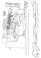
- the housing and covering casing of the splicing device is shown, the latter being generically indicated by the reference 11.
- the device 11 comprises a supporting plate 12, slidably mounted onto guiding and sliding brackets 13.
- the supporting plate 12 is internally hollow (being formed by a prismatic casing having substantially trapezoidal cross-section), and its upper surface is formed by a fixed plate 14, wherein an opening 15 is provided. Cross-wise with respect to the opening 15 a bridge 16 is mounted, rigidly connected to a plate 17.
- the latter together with the bridge 16, can be displaced parallel to itself so as to be brought towards or away with respect to the fixed plate 14 and consequently with respect to its terminal edge.
- cylindrical holes 18 are provided forming the seat for tapered pins 19; the latter are vertically movable between a rest position in which are completely housed in the respective hole 18 and an operating position in which protrude from the surface of the supporting plate 12.
- pneumatic cylinder 34 is shown in simplified form but it is evident that it cooperates with a double effect piston fastened to the support 35.
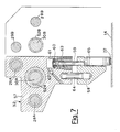
- Two gripping and dragging elements are fastened to the support 35, the fastening being carried out so that the upper element 36 is vertically displaceable with respect to the support 35 and so that the element 37, hereinafter called plying element, is vertically displaceable with respect to the gripping element 36.
- the element 36 comprises a cylindrical hole 38 vertically aligned with a cylindrical hole formed in the support 35, into the two holes being seated the stem 39 of a piston 40 housed in the cylinder 41 provided in the body of the support 35 and fed in a controlled manner with air pressure through the duct 42.
- the stem 38 of the piston 39 is rigidly connected at its end to the gripping element 36 and a spring 43 opposes the downward displacement of the piston 40 and thus of the stem 39 reacting between the piston and the seat 44 provided in the support 35.
- the plying element 37 is rigidly connected through a stem 45 to a piston 46 slidable into a cyclinder 47 provided in the gripping element 36, the displacement of the piston 46 being controlled by air pressure fed to the duct 48 and being resiliently opposed by a contrasting spring 49.
- the plying element 37 has the end shaped as a tapered pallet 50, whereby in the position of fig. 4 namely with the support 35 displaced into the operating position, the plying element 37 is positioned across the contacting and splicing line, indicated by the reference 51 in figure 1.
- the movement of the gripping and dragging device 31 along the bars 29B, 28B is controlled by an internally threaded sleeve 52B, rigidly fixed to the block 43, the screw threaded bar 30B being rotated by means of a kinematic device positioned at rear end and actuated from a reversible electrical motor 53 through the chain 54, the pinion 55 and the chain 56. Since it is a motion transmission of conventional type, a more detailed description is not necessary, it being meant that the screw threaded bar 30B is rotated in either directions for the number of rotations needed to sequentially displace the screw threaded sleeve 52B and consequently the gripping device 31 in the several desidered positions.
- the pressing roller device 32 comprises a block 57 also L-shaped as the block 33, with respect to which it is mirror like symmetrically as regards the engagement with the bars 28A, 29A and the actuation through the screw threaded bar 30A and the screw threaded sleeve 52A cooperating therewith.
- the support 58 is rigidly connected to the end of the stem 59 of the piston 60 housed into a cylinder 61, the stem being slidable withing a cylindrical hole formed in the base of the block 57.
- a feed 62 of air pressure is provided whereas the operating displacement of the piston 60 is opposed by a spring 63.
- a pin 64 prevents the support 58 from rotating around the axis of the stem 59 and a pressure roller 65, covered by a suitable anti-adhesive material, is mounted to the support 58 by means of the pin 66, the roller being positioned so as to be placed across of the splicing line 51 and having an axial length corresponding to that of splicing self-adhesive tape 72.
- the latter is drawn from a bobbin housed in the supporting plane 12, which is moreover provided with the control photocell 67 fastened to the displaceable plate 17 and having the subsequently described function.
- the device it is first of all to be pointed out that it must be retractable so that, once the splicing operation is carried out, the package from which the first sheet has been drawn can be freely displaced in substitution of that feeding the printer, when the latter package is exhausted.
- pins 19 must be retractable, since they when oc cupy the protruding position serve to position with precision the two sheets to be spliced so that their head edges are exactly approached at the splicing line 51, without hindering the return or withdrawal of the splicing device ones displacing operation is carried out, for the above indicated reasons.
- the splicing plane 12 is extracted, by displacing it along the guiding and sliding bars 22, whereby also the splicing head is extracted.
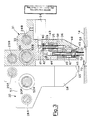
- the first operation is that of the actuation of the piston 46, whereby the plying element 37 is lowered with respect to the supporting plane so as to be removed from the gripping element 36 (fig. 3).
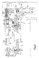
- the cylinder 34 is actuated, whereby the support 35 is displaced to the left (looking at the fig. 3) and the plying element takes the position below the self-adhesive tape 72, the free end of which, resulting from the next preceeding splicing operation, remained laid down between the cutting resistance 21 and residual rear part of the supporting plate 12. Otherwise stated the plying element 37 is inserted below the tape 72 in the space indicated by the reference 68 in figure 2.
- the device 31 is now ready for laying the tape 72 with the adhesive surfance downwardly directed and this operation is carried out by controlling the rotation of the screw threaded bar 30B, whereby the screw threaded sleeve 52B and the block 33 are displaced towards the end of the splicing head until the terminal edge of the supporting plane is trespassed, then stopping in the position of the device 31 as illustrated by solid lines in fig. 2.
- the self-adhesive tape 72 laid down along the contact or splicing line 51, is lowered coming into contact with the adjacent edges of the two sheets to be spliced .
- the pressing device is actuated by rotating the screw threaded bar 30A, by which the displacement of the block 57 and thus of the device 32, starting from the position illustrated in solid lines in fig. 2, is caused to take place.
- the cutting resistances 21 are energized, namely the electrical power is switched on and the same resistances are pushed upwardly thus cutting the adhesive tape 72 flush of the said edges of the two sheets to be spliced.
- the cylinder and piston assembly 60,61 is deenergized, whereby under the effect of the springs 63 the support 58 and the roller 65 are lifted with respect to the plate 12; thereafter the screw threaded bar 30A is rotated in the opposite direction and the device 32 comes back to the rest position.
- the front panel of the splicing plane 12 is provided with control push buttons, it being meant that the operating sequence can be made totally automatic, without manual intervention, apart from that of positioning the two sheets to be spliced and the actuation of the push button for starting the splicing cycle.
Landscapes
- Engineering & Computer Science (AREA)
- Textile Engineering (AREA)
- Replacement Of Web Rolls (AREA)
Applications Claiming Priority (2)
| Application Number | Priority Date | Filing Date | Title |
|---|---|---|---|
| IT2173886 | 1986-09-17 | ||
| IT8621738A IT1206350B (it) | 1986-09-17 | 1986-09-17 | Dipsositivo di giunzione per materiale in foglio. |
Publications (2)
| Publication Number | Publication Date |
|---|---|
| EP0260694A2 true EP0260694A2 (de) | 1988-03-23 |
| EP0260694A3 EP0260694A3 (de) | 1990-01-17 |
Family
ID=11186177
Family Applications (1)
| Application Number | Title | Priority Date | Filing Date |
|---|---|---|---|
| EP87113617A Withdrawn EP0260694A3 (de) | 1986-09-17 | 1987-09-17 | Anklebevorrichtung für bogenförmiges Gut |
Country Status (4)
| Country | Link |
|---|---|
| US (1) | US4832786A (de) |
| EP (1) | EP0260694A3 (de) |
| JP (1) | JPS63147753A (de) |
| IT (1) | IT1206350B (de) |
Families Citing this family (5)
| Publication number | Priority date | Publication date | Assignee | Title |
|---|---|---|---|---|
| US5004515A (en) * | 1988-04-22 | 1991-04-02 | Kabushiki Kaisha Sankyo Seiki Seisakusho | Automatic paper feeder |
| US5242527A (en) * | 1989-02-09 | 1993-09-07 | Industria Grafica Meschi S.R.L. | Splicing apparatus for printer supply |
| IT1318297B1 (it) * | 2000-08-01 | 2003-07-28 | Giuseppe Caccia | Dispositivo per l'applicazione automatica di supporti protettivi salva cuciture, per tessuti e/o affini in movimento. |
| ATE468797T1 (de) * | 2004-12-29 | 2010-06-15 | Sca Hygiene Prod Ab | Freihand-papiertuchspender und spendersystem |
| CN116619921B (zh) * | 2023-06-25 | 2023-11-10 | 杭州兆臻网络科技有限公司 | 一种自助打印终端 |
Family Cites Families (9)
| Publication number | Priority date | Publication date | Assignee | Title |
|---|---|---|---|---|
| US2827104A (en) * | 1956-08-09 | 1958-03-18 | Universal Business Machines | Forms splicing machine |
| GB920528A (en) * | 1960-08-19 | 1963-03-06 | Paragon Ab Oy | Improvements in or relating to devices for joining stationery |
| US3769140A (en) * | 1972-01-04 | 1973-10-30 | Eastman Kodak Co | Adjustable web splicing device |
| US4289556A (en) * | 1979-08-06 | 1981-09-15 | Paper, Inc. | Method and apparatus for splicing folded paper |
| CH646666A5 (it) * | 1980-06-23 | 1984-12-14 | Wully Sa | Procedimento ed apparecchio per la giuntatura di materiale in foglio e per l'alimentazione continua di stampanti veloci. |
| GB2123801B (en) * | 1982-07-17 | 1986-06-25 | Hurley Moate Eng | Improvments in or relating to splicing webs |
| DE3328255A1 (de) * | 1983-08-04 | 1985-02-21 | Siemens AG, 1000 Berlin und 8000 München | Klebestation fuer einen schnelldrucker |
| ATE76358T1 (de) * | 1984-07-13 | 1992-06-15 | Mauro Lenzi | Ununterbrochene papierzufuhr fuer einen schnelldrucker. |
| US4576673A (en) * | 1984-07-19 | 1986-03-18 | Mauro Lenzi | Service unit intended to continuously supply a high-speed printer with preformed support packages |
-
1986
- 1986-09-17 IT IT8621738A patent/IT1206350B/it active
-
1987
- 1987-09-16 US US07/097,195 patent/US4832786A/en not_active Expired - Fee Related
- 1987-09-17 JP JP62233593A patent/JPS63147753A/ja active Pending
- 1987-09-17 EP EP87113617A patent/EP0260694A3/de not_active Withdrawn
Also Published As
| Publication number | Publication date |
|---|---|
| JPS63147753A (ja) | 1988-06-20 |
| IT1206350B (it) | 1989-04-14 |
| EP0260694A3 (de) | 1990-01-17 |
| US4832786A (en) | 1989-05-23 |
| IT8621738A0 (it) | 1986-09-17 |
Similar Documents
| Publication | Publication Date | Title |
|---|---|---|
| EP0117273B1 (de) | Vorrichtung zum automatischen Befestigen von Steckern an Kabelenden | |
| US6227088B1 (en) | Apparatus for opening paper bobbins | |
| CA2224053A1 (en) | Apparatus for moving a paper sheet | |
| US4553420A (en) | Method and apparatus for touch-free lead bending | |
| EP0260694A2 (de) | Anklebevorrichtung für bogenförmiges Gut | |
| US4901434A (en) | Apparatus for terminating multiconductor cable by pressure connection | |
| CH646666A5 (it) | Procedimento ed apparecchio per la giuntatura di materiale in foglio e per l'alimentazione continua di stampanti veloci. | |
| US5120147A (en) | Printing device | |
| US4982636A (en) | Measured leader length supply system | |
| US4610124A (en) | Method of bundling elongate articles | |
| IT8322818A1 (it) | Macchina per contrassegnare conduttori elettrici e simili | |
| GB2143477A (en) | A sheet guide for a printer | |
| JPS6121903B2 (de) | ||
| DE69015246T2 (de) | Drucker für strichkodiertes Papier. | |
| US2813021A (en) | Machine for pinning tickets and the like to articles | |
| EP0041579B1 (de) | Anordnung zum zusammenpacken eines farbbandes für einen drucker | |
| US4729813A (en) | Splicing head for sheet material | |
| US2110855A (en) | Paper feeding device | |
| EP0657904A1 (de) | Streifenanbringeeinheit auf Spule | |
| JPS60175315A (ja) | リボンケ−ブル用自動圧接機 | |
| IT9019581A1 (it) | Apparecchiatura e metodo di alimentazione di etichette | |
| JP2505233Y2 (ja) | 熱転写式プリンタ | |
| JPS6010867Y2 (ja) | 安全機構を有する単票印刷機 | |
| JPH0326619A (ja) | 給紙機構 | |
| JPH0790978B2 (ja) | ボビン端の重ね巻糸条の除去方法及び重ね巻糸条の切断装置 |
Legal Events
| Date | Code | Title | Description |
|---|---|---|---|
| PUAI | Public reference made under article 153(3) epc to a published international application that has entered the european phase |
Free format text: ORIGINAL CODE: 0009012 |
|
| AK | Designated contracting states |
Kind code of ref document: A2 Designated state(s): AT BE CH DE ES FR GB GR IT LI LU NL SE |
|
| PUAL | Search report despatched |
Free format text: ORIGINAL CODE: 0009013 |
|
| AK | Designated contracting states |
Kind code of ref document: A3 Designated state(s): AT BE CH DE ES FR GB GR IT LI LU NL SE |
|
| 17P | Request for examination filed |
Effective date: 19900531 |
|
| 17Q | First examination report despatched |
Effective date: 19910903 |
|
| STAA | Information on the status of an ep patent application or granted ep patent |
Free format text: STATUS: THE APPLICATION IS DEEMED TO BE WITHDRAWN |
|
| 18D | Application deemed to be withdrawn |
Effective date: 19920314 |