EP0260745A1 - Vorrichtung zur optischen heterodynen Detektion eines optischen Signals und optisches Übertragungssystem mit einer solchen Vorrichtung - Google Patents
Vorrichtung zur optischen heterodynen Detektion eines optischen Signals und optisches Übertragungssystem mit einer solchen Vorrichtung Download PDFInfo
- Publication number
- EP0260745A1 EP0260745A1 EP87201709A EP87201709A EP0260745A1 EP 0260745 A1 EP0260745 A1 EP 0260745A1 EP 87201709 A EP87201709 A EP 87201709A EP 87201709 A EP87201709 A EP 87201709A EP 0260745 A1 EP0260745 A1 EP 0260745A1
- Authority
- EP
- European Patent Office
- Prior art keywords
- polarisation
- signal
- radiation
- state
- optical
- Prior art date
- Legal status (The legal status is an assumption and is not a legal conclusion. Google has not performed a legal analysis and makes no representation as to the accuracy of the status listed.)
- Withdrawn
Links
- 230000003287 optical effect Effects 0.000 title claims description 33
- 238000001514 detection method Methods 0.000 title claims description 28
- 230000005540 biological transmission Effects 0.000 title claims description 14
- 230000005855 radiation Effects 0.000 claims abstract description 72
- 239000000835 fiber Substances 0.000 claims description 7
- 239000002131 composite material Substances 0.000 description 5
- 238000010586 diagram Methods 0.000 description 5
- 239000013307 optical fiber Substances 0.000 description 5
- 238000000034 method Methods 0.000 description 4
- 239000004065 semiconductor Substances 0.000 description 4
- 230000008901 benefit Effects 0.000 description 3
- 230000008859 change Effects 0.000 description 2
- KRKNYBCHXYNGOX-UHFFFAOYSA-N citric acid Chemical compound OC(=O)CC(O)(C(O)=O)CC(O)=O KRKNYBCHXYNGOX-UHFFFAOYSA-N 0.000 description 2
- 230000001427 coherent effect Effects 0.000 description 2
- 230000001419 dependent effect Effects 0.000 description 2
- 230000005684 electric field Effects 0.000 description 2
- 230000009467 reduction Effects 0.000 description 2
- 238000001228 spectrum Methods 0.000 description 2
- 238000006243 chemical reaction Methods 0.000 description 1
- 230000008878 coupling Effects 0.000 description 1
- 238000010168 coupling process Methods 0.000 description 1
- 238000005859 coupling reaction Methods 0.000 description 1
- 239000013078 crystal Substances 0.000 description 1
- 238000005516 engineering process Methods 0.000 description 1
- 238000007689 inspection Methods 0.000 description 1
- 230000007935 neutral effect Effects 0.000 description 1
- 229940125730 polarisation modulator Drugs 0.000 description 1
- 230000001902 propagating effect Effects 0.000 description 1
- 238000006467 substitution reaction Methods 0.000 description 1
- 230000007704 transition Effects 0.000 description 1
- 239000013598 vector Substances 0.000 description 1
Images


Classifications
-
- H—ELECTRICITY
- H04—ELECTRIC COMMUNICATION TECHNIQUE
- H04B—TRANSMISSION
- H04B10/00—Transmission systems employing electromagnetic waves other than radio-waves, e.g. infrared, visible or ultraviolet light, or employing corpuscular radiation, e.g. quantum communication
- H04B10/60—Receivers
- H04B10/61—Coherent receivers
-
- H—ELECTRICITY
- H04—ELECTRIC COMMUNICATION TECHNIQUE
- H04B—TRANSMISSION
- H04B10/00—Transmission systems employing electromagnetic waves other than radio-waves, e.g. infrared, visible or ultraviolet light, or employing corpuscular radiation, e.g. quantum communication
- H04B10/60—Receivers
- H04B10/61—Coherent receivers
- H04B10/614—Coherent receivers comprising one or more polarization beam splitters, e.g. polarization multiplexed [PolMux] X-PSK coherent receivers, polarization diversity heterodyne coherent receivers
-
- H—ELECTRICITY
- H04—ELECTRIC COMMUNICATION TECHNIQUE
- H04B—TRANSMISSION
- H04B10/00—Transmission systems employing electromagnetic waves other than radio-waves, e.g. infrared, visible or ultraviolet light, or employing corpuscular radiation, e.g. quantum communication
- H04B10/60—Receivers
- H04B10/61—Coherent receivers
- H04B10/64—Heterodyne, i.e. coherent receivers where, after the opto-electronic conversion, an electrical signal at an intermediate frequency [IF] is obtained
Definitions
- the invention relates to a device for optical heterodyne detection of an optical signal beam, comprising a local oscillator, a polarisation-sensitive beam splitter for splitting the signal beam into two orthogonally polarised components, an element for combining radiation of the signal beam with radiation of the local oscillator, and two opto-electric converters which are arranged in the radiation paths of the two orthogonally polarised components, respectively.
- the invention also relates to an optical transmission system provided with such a detection device.
- a device of this type is known from British Patent Application no. 2,110,895 laid open to public inspection.
- heterodyne detection provides considerable advantages relating to the signal-to-noise ratio and the discrimination of background radiation.
- the principle of heterodyne detection of optical radiation has been described extensively in the Article "Optical Heterodyne Detection” by O.E. DeLange in the journal “IEEE Spectrum” of October 1968, pages 77-85. As is stated in this Article it is important that the polarisation states of the modulated signal beam and the local oscillator beam correspond as much as possible.
- optical transmission systems use optical waveguides or optical fibres, which have a disturbing influence on the state of polarisation of the. radiation propagating therein.
- These fibres which may be several dozen to several hundred kilometres long, are subjected to uncontrollable external influence such as temperature and pressure variations so that the disturbance of the polarisation state may vary in time.
- a signal beam linearly polarised at the input of a transmission fibre will generally be distorted at the output to an elliptically polarised beam whose ellipticity and direction of the major axis vary in time.
- a device is characterized in that an element to influence the state of polarisation is arranged in the radiation path of the local oscillator beam, which element influences the state of polarisation of the radiation passing therethrough in dependence upon a control signal derived from the output signal of the two opto-electric converters so that the local oscillator beam is brought to a state of polarisation whose ratio between the amplitudes of the orthogonally polarised components is substantially equal to the comparable ratio of the radiation in the signal beam.
- the signal-to-noise ratio of the combined signal is independent of the state of polarisation of the signal beam when using the invention.
- An advantage of great practical value in this device is that only the ratio between the amplitudes of the polarised components and not the phase difference between the components is important.
- This provides the possibility of controlling the state of polarisation of the local oscillator beam by means of a limited range control, which from a constructive point of view has advantages with respect to an endless control.
- Controllable elements influencing the state of polarisation are known, for example, from the Article "Polarisation-State Control Schemes for Heterodyne or Homodyne Optical Fiber Communications" by T. Okoshi in the journal “IEEE Journal of Lightwave Technology” Vol.
- the signal-to-noise ratio can be maintained at the optimum value only in the case of limited variations of the state of polarisation, unless interruptions in the control and consequently a temporary signal loss are accepted.
- a first embodiment of the device according to the invention is characterized in that it comprises two polarisation-sensitive beam splitters and two beam-combining elements, in that the first polarisation-sensitive beam splitter is arranged in the radiation path of the signal beam, in that the second polarisation-sensitive beam splitter is arranged in the radiation path of the beam emerging from the element to influence the state of polarisation, in that the first beam-combining element combines the first corresponding beam component from the two polarisation-sensitive beam splitters, in that the second beam-combining element combines the second corresponding beam component from the two polarisation-sensitive beam splitters and in that the two opto-electric converters are arranged in the respective radiation paths of the combined beams.
- a second embodiment of the device according to the invention is characterized in that it comprises one beam-combining element and one polarisation-sensitive beam splitter, in that the beam-combining element is arranged in the radiation paths of the signal beam and of the beam emerging from the element to influence the state of polarisation, and in that the polarisation-sensitive beam splitter is arranged between the beam-combining element and the two opto-electric converters.
- disturbances which influence the- polarisation states of the beams which have been combined and split into components have an equal influence on the radiation originating from the signal beam and from the local oscillator.
- optical fibres can thus be used which do not ensure that the state of polarisation is preserved, but which provide the possibility of a compact structure of the detection device and low radiation losses in the various optical elements.
- This embodiment of the device according to the invention is preferably further characterized in that the beam-combining element is a directional fibre-optic coupler. With this element a combination of the signal beam and of the local oscillator beam can be established without coupling losses at the entrance and exit faces of the coupler.
- a device may be further characterized in that the radiation paths of radiation emerging from two outputs of a beam-combining element accommodate polarisation-sensitive beam splitters, in that each of the radiation paths of the beam components emerging from the polarisation-sensitive beam splitters accommodates an opto-electric converter and in that the output signals of the converters in the radiation paths of equally polarised components are combined in differential amplifiers.
- the beam-combining element is preferably formed in such a manner that radiation of each of the two inputs is equally distributed over the two outputs.
- the invention also relates to an optical transmission system comprising a radiation source unit for generating a linearly polarised signal beam modulated with an information signal, an optical transmission fibre transmitting the signal beam and a detection device reducing the carrier frequency of the signal beam.
- This optical transmission system according to the invention is characterized in that the detection device is a device for optical heretodyne detection of a signal beam in accordance with any one of the above- mentioned embodiments.
- the radiation source unit comprises, for example, a semi-conductor laser making it possible to generate a frequency-modulated signal beam by modulating the current passed therethrough.
- the radiation source unit may comprise a separate modulator for phase-or frequency- modulation of the signal beam.
- the reference numeral 1 denotes an optical signal beam which is split into two linearly polarised components 3 and 4 by the polarisation splitter cube 2, with, for example 3 being polarised horizontally and 4 being polarised vertically which is denoted by an arrow in the plane of the drawing and by an arrow perpendicularly to the plane of the drawing, respectively.
- a local oscillator 5 emits a linearly and horizontally polarised beam 6 which is split by a neutral beam splitter 7, for example a semitransparent mirror, into two likewise horizontally polarised beams 8 and 9.
- the horizontally polarised beams 3 and 8 are combined in the beam-combining element 11 to a composite beam 13.
- the beam 9 passes through a polarisation-rotating element 10, for example a ⁇ /2 plate placed in a diagonal position so that the beam is polarised vertically. Subsequently this beam is combined in the beam-combining element 12 with the vertically polarised component 4 of the signal beam to a composite beam 14.
- a polarisation-rotating element 10 for example a ⁇ /2 plate placed in a diagonal position so that the beam is polarised vertically.
- the two composite beams 13 and 14 are detected by means of two opt-electric converters 15 and 16.
- the beams 13 and 14 can be considered to be composed of a number of frequency components one of which has a frequency which is equal to the difference of the frequencies of the signal beam and of the local oscillator beam.
- the other components have frequencies which are approximately twice the frequencies of the last-mentioned beams.
- the opto-electric converters 15 and 16 are not capable of following these high-frequency components but they can follow the difference component.
- the high-frequency components give rise to a d.c. component in the output signal.
- the modulation of the signal beam is transferred to the difference component so that the electrical output signals 17 and 18 have a a.c. components whose modulation corresponds to the modulation of the signal beam.
- the circuit 19 combines the signals 17 and 18 to a final signal 20.
- the signal-to-noise ratio which is obtained with the above described known heterodyne detection device can be determined as follows:
- the instantaneous value of the alternating current is the output signal 20 of the combination circuit 19 is: wherein E ox' E o y represent the amplitudus of the electrical fields in the two polarisation directions and o is the frequency of the radiation of the local oscillator and E sx' E sy and s denote the corresponding quantities of the radiation from the signal beam.
- the noise level in the end signal 20 is equal to the sum of the noise in the two separate signals 17 and 18:
- the signal-to-noise ration then is:
- the power of the local oscillator is distributed equally over the two polarisation directions, hence: Assuming that the power in the signal beam is distributed over the two polarisation components in the ratio a:(1-a), hence and it follows for the signal-to-noise ratio that:
- the signal-to-noise ration is dependent on the ratio in which the signal beam power is distributed over the two mutually perpendicularly polarised beam components.
- Fig. 2 illustrates the detection method according to the invention.
- the layout of Fig. 2 is equal to that of Fig. 1 to which reference is made for the part not described hereinafter.
- the linearly polarised radiation beam 6 originating from the local oscillator 5 is passed through an element 21 influencing the polarisation state.
- the radiation emerging therefrom is split in the polarisation splitter cube 22 into two orthogonally and linearly polarised components 8 and 9 in which, which reference to Fig. 1, 8 is polarised horizontally and 9 is polarised vertically.
- the relative ratio of the amplitudes of the radiation in the beams 8 and 9 can be influenced by influencing the state of polarisation by means of the element 21.
- a change of the polarisation state of the signal beam implies a change of a, with z remaining equal. This results in a reduction of the magnitude of the output signal 20.
- the value of z can be kept substantially equal to that of a. This control is not shown in detail in the drawing.
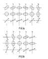
- Figs. 3a and 3b show states of polarisation which the radiation in the signal beam can assume as a result of the external influences acting on the optical transmission fibre.
- the lower parts show possible polarisation states of the radiation of the local oscillator.
- Fig. 3a shows the polarisation state of the signal beam at six not necessarily equidistant points of time ti to ts.
- the signal beam is elliptically polarised with an equal ellipticity at each instant.
- the major axis of the ellipse is rotated clockwise through 22.5° from one instant to the next.
- the central part and the lower part show two possible states of polarisation for the beam of radiation originating from the local oscillator which can be combined with the signal beam in order to achieve an optimum heterodyne detection.
- the central series of diagrams shows possible deformations of the polarisation of this beam of radiation which is in principle elliptical.
- the orientation of the two ellipse axes remains the same, but only the length of the two axes is varied.
- the lower series of diagrams shows how the invention can be used with a linearly polarised beam of the local oscillator. By changing the direction of polarisation the ratio between the horizontal and the vertical components can be modified.
- the latter series of diagrams also illustrates that the direction of polarisation need only be varied over a limited range.
- Fig. 3b shows how the state of polarisation of the signal beam can vary in a different manner.
- the points of time ti to t 5 shown indicate transition phases from a linear state of polarisation via elliptical, circular and again elliptical polarisation to an orthogonal linear polarisation state.
- the central and the lower series of diagrams in this Figure show two manners in which the local oscillator can be corrected according to the invention.
- the central series of diagrams indicates how this is effected by adapting the ellipticity of the local oscillator radiation, whilst the lower series shows the rotation of the polarisation direction of the linearly polarised radiation from the local oscillator.
- Fig. 4 shows diagrammatically an embodiment of a detection device.
- the reference numeral 31 denotes the end of a long-distance monomode optical transmission fibre through which an optical signal beam is transmitted.
- a local oscillator 32 generates optical radiation at a fixed polarisation state.
- This local oscillator is, for example, a semiconductor laser.
- the radiation beam originating from the local oscillator traverses an element 33 influencing the polarisation state, for example a Faraday rotator, an electro-optical crystal or a fibre squeezer which brings the beam to a state of polarisation in which the ratio of the intensities of the horizontal and the vertical components is equal to that of the corresponding components in the signal beam.
- element 35 is preferably asymetric, that is to say, the combined radiation beam in the output 36 comprises a large portion of the signal radiation and only a small portion of the local oscillator radiation.
- element 35 is shown as a directional fibre-optic coupler but this element may be alternatively, for example, a semitransparent mirror.
- the composite beam emerging from the element 35 is subsequently split in a polarisation-sensitive beam splitter 37, for example, a Wollaston prism, into a horizontally polarised component and a vertically polarised component.
- Each of the two components is separately detected in the opto-electric converters 41 and 42, for example, radiation-sensitive diodes.
- the output signals 43 and 44 of the converters are added to the circuit 45 which combines several functions. In the first place the output signals of the opto-electric converters are added together, if necessary after a phase correction, and they constitute the end signal 47. In the second place a control signal 46 is generated in the circuit 45 with which signal the adjustment of the element 33 influencing the state of polarisation is varied and is readjusted, if necessary, in order to compensate for changes in the state of polarisation of the signal beam.
- Fig. 5 shows an alternative possibility of detecting the composite beam.
- the radiation from the two outputs of the coupler is used.
- the reference numeral 31 in Fig. 4 denotes the end of an optical fibre through which a signal beam is transmitted
- the reference numeral 32 denotes a local oscillator
- the reference numeral 33 denotes an element influencing the polarisation state
- the reference numeral 35 denotes a beam-combining element.
- the radiation originating from the signal beam and from the local oscillator is preferably distributed equally over the two outputs 51 and 52 of the coupler.
- the radiation emerging from each of the two outputs is added to one of two polarisation-sensitive beam splitters 53 and 54, respectively, which splits the incoming radiation into two orthogonally polarised components which are detected in the opto-electric converters 61, 62, 63 or 64.
- the converters 61 and 63 detecting the horizontally polarised components add their output signals to the differential amplifier 65.
- the outputs of the converters 62 and 64 detecting the vertical components are connected to the inputs of the differential detector 66. Since beams from the two outputs 51 and 52 of the element 35 have opposite phases, the d.c. components of output signals of the converters are cancelled in the differential amplifiers 65 and 66 and the a.c. components are added together.
- the output signals of the differential amplifiers 65 and 66 are added to the combination and control circuit 67 which supplies a control signal 68 for the element 33 to influence the state of polarisation and final signal 69.
- a radiation source unit 80 comprises a radiation source 81, for example, a semiconductor laser which emits radiation which is modulated in the electro-optical modulator 82 with the information signal S.
- the radiation source unit may comprise a semiconductor laser as a radiation source in which the signal beam is frequency-modulated by changing the current which is passed through the laser.
- the optical signal is transmitted through the long-distance transmission fibre 83 to one of two inputs of the optic coupler 84.
- the other input of the coupler 84 is connected to the output of a local oscillator 85 via an element 86 to influence the state of polarisation.
- the radiation from one of from both outputs of the coupler is split into horizontally polarised components and vertically polarised components by the polarisation-sensitive beam splitter 87.
- Each of the components is detected by one of the opto-electric converters 88 and 89.
- a control signal for the element 86 influencing the polarisation state and the output signal S' are determined from the output signals thereof.
Landscapes
- Physics & Mathematics (AREA)
- Electromagnetism (AREA)
- Engineering & Computer Science (AREA)
- Computer Networks & Wireless Communication (AREA)
- Signal Processing (AREA)
- Optical Communication System (AREA)
Applications Claiming Priority (2)
| Application Number | Priority Date | Filing Date | Title |
|---|---|---|---|
| NL8602350 | 1986-09-17 | ||
| NL8602350A NL8602350A (nl) | 1986-09-17 | 1986-09-17 | Inrichting voor optische heterodyne detektie van een optische signaalbundel en optisch transmissiesysteem voorzien van een dergelijke inrichting. |
Publications (1)
| Publication Number | Publication Date |
|---|---|
| EP0260745A1 true EP0260745A1 (de) | 1988-03-23 |
Family
ID=19848563
Family Applications (1)
| Application Number | Title | Priority Date | Filing Date |
|---|---|---|---|
| EP87201709A Withdrawn EP0260745A1 (de) | 1986-09-17 | 1987-09-10 | Vorrichtung zur optischen heterodynen Detektion eines optischen Signals und optisches Übertragungssystem mit einer solchen Vorrichtung |
Country Status (2)
| Country | Link |
|---|---|
| EP (1) | EP0260745A1 (de) |
| NL (1) | NL8602350A (de) |
Cited By (11)
| Publication number | Priority date | Publication date | Assignee | Title |
|---|---|---|---|---|
| EP0345889A1 (de) * | 1988-06-10 | 1989-12-13 | Koninklijke Philips Electronics N.V. | Vorrichtung für optischen Heterodynempfang und integrierter optischer Bauteil zur Anwendung in einer derartigen Vorrichtung |
| EP0372807A3 (en) * | 1988-12-03 | 1990-12-12 | Kabushiki Kaisha Toshiba | Optical mixing device |
| GB2245117A (en) * | 1990-06-14 | 1991-12-18 | Stc Plc | Optical mixing for heterodyne detection |
| EP0271934B1 (de) * | 1986-11-12 | 1995-09-13 | Koninklijke Philips Electronics N.V. | Gerät zur optischen Überlagerungsdetektion eines optischen Signalstrahls und optisches Übertragungssystem mit einem solchen Gerät |
| WO2001067649A1 (de) * | 2000-03-04 | 2001-09-13 | Profile Optische Systeme Gmbh | Vorrichtung zur erfassung der pmd von optoelektronischen übertragungsstrecken |
| WO2002005463A1 (de) * | 2000-07-12 | 2002-01-17 | Profile Optische Systeme Gmbh | Pdm-monitor-verfahren und anordnung zur ermittlung der polarisations-moden-dispersion eines transmissionssystems und insbesondere einer transmissionsfaser |
| US7262848B2 (en) | 2001-05-17 | 2007-08-28 | Thorlabs Gmbh | Fiber polarimeter, the use thereof, as well as polarimetric method |
| US7495765B2 (en) | 2001-05-17 | 2009-02-24 | Thorlabs Gmbh | Fiber polarimeter, the use thereof, as well as polarimetric method |
| EP3886342A1 (de) * | 2020-03-24 | 2021-09-29 | Mitsubishi Electric R & D Centre Europe B.V. | Kohärenter optischer empfänger |
| EP4117201A1 (de) * | 2021-07-06 | 2023-01-11 | Mitsubishi Electric R & D Centre Europe B.V. | Kohärenter optischer empfänger |
| EP4117202A1 (de) * | 2021-07-09 | 2023-01-11 | Mitsubishi Electric R & D Centre Europe B.V. | Kohärenter optischer empfänger |
Citations (3)
| Publication number | Priority date | Publication date | Assignee | Title |
|---|---|---|---|---|
| JPS6047524A (ja) * | 1983-08-26 | 1985-03-14 | Nippon Telegr & Teleph Corp <Ntt> | 光受信装置 |
| US4506388A (en) * | 1981-11-26 | 1985-03-19 | Michel Monerie | Process and apparatus for the coherent detection and demodulation of a phase-modulated carrier wave in a random polarization state |
| WO1986007513A1 (en) * | 1985-06-06 | 1986-12-18 | British Telecommunications Public Limited Company | Coherent optical receivers |
-
1986
- 1986-09-17 NL NL8602350A patent/NL8602350A/nl not_active Application Discontinuation
-
1987
- 1987-09-10 EP EP87201709A patent/EP0260745A1/de not_active Withdrawn
Patent Citations (3)
| Publication number | Priority date | Publication date | Assignee | Title |
|---|---|---|---|---|
| US4506388A (en) * | 1981-11-26 | 1985-03-19 | Michel Monerie | Process and apparatus for the coherent detection and demodulation of a phase-modulated carrier wave in a random polarization state |
| JPS6047524A (ja) * | 1983-08-26 | 1985-03-14 | Nippon Telegr & Teleph Corp <Ntt> | 光受信装置 |
| WO1986007513A1 (en) * | 1985-06-06 | 1986-12-18 | British Telecommunications Public Limited Company | Coherent optical receivers |
Non-Patent Citations (2)
| Title |
|---|
| ELECTRONICS LETTERS, vol. 21, no. 2, 17th January 1985, pages 52-53, Stevenage, Herts, GB; T. IMAI et al.: "Optical polarisation control utilising an optical heterodyne detection scheme" * |
| PATENT ABSTRACTS OF JAPAN, vol. 9, no. 178, 23rd July 1985, page 36 E 330; & JP-A-60 47 524 (NIPPON DENSHIN DENWA KOSHA) 14-03-1985 * |
Cited By (18)
| Publication number | Priority date | Publication date | Assignee | Title |
|---|---|---|---|---|
| EP0271934B1 (de) * | 1986-11-12 | 1995-09-13 | Koninklijke Philips Electronics N.V. | Gerät zur optischen Überlagerungsdetektion eines optischen Signalstrahls und optisches Übertragungssystem mit einem solchen Gerät |
| EP0345889A1 (de) * | 1988-06-10 | 1989-12-13 | Koninklijke Philips Electronics N.V. | Vorrichtung für optischen Heterodynempfang und integrierter optischer Bauteil zur Anwendung in einer derartigen Vorrichtung |
| EP0372807A3 (en) * | 1988-12-03 | 1990-12-12 | Kabushiki Kaisha Toshiba | Optical mixing device |
| US5056887A (en) * | 1988-12-03 | 1991-10-15 | Kabushiki Kaisha Toshiba | Optical mixing device |
| GB2245117A (en) * | 1990-06-14 | 1991-12-18 | Stc Plc | Optical mixing for heterodyne detection |
| GB2245117B (en) * | 1990-06-14 | 1994-04-06 | Stc Plc | Optical mixing for heterodyne detection |
| US6885783B2 (en) | 2000-03-04 | 2005-04-26 | Thorlabs Gmbh | Device for detecting the PMD of optoelectronic transmission lines |
| WO2001067649A1 (de) * | 2000-03-04 | 2001-09-13 | Profile Optische Systeme Gmbh | Vorrichtung zur erfassung der pmd von optoelektronischen übertragungsstrecken |
| WO2002005463A1 (de) * | 2000-07-12 | 2002-01-17 | Profile Optische Systeme Gmbh | Pdm-monitor-verfahren und anordnung zur ermittlung der polarisations-moden-dispersion eines transmissionssystems und insbesondere einer transmissionsfaser |
| US7262848B2 (en) | 2001-05-17 | 2007-08-28 | Thorlabs Gmbh | Fiber polarimeter, the use thereof, as well as polarimetric method |
| US7495765B2 (en) | 2001-05-17 | 2009-02-24 | Thorlabs Gmbh | Fiber polarimeter, the use thereof, as well as polarimetric method |
| EP3886342A1 (de) * | 2020-03-24 | 2021-09-29 | Mitsubishi Electric R & D Centre Europe B.V. | Kohärenter optischer empfänger |
| WO2021192451A1 (en) * | 2020-03-24 | 2021-09-30 | Mitsubishi Electric Corporation | Coherent optical receiver and optical network unit |
| EP4117201A1 (de) * | 2021-07-06 | 2023-01-11 | Mitsubishi Electric R & D Centre Europe B.V. | Kohärenter optischer empfänger |
| WO2023281770A1 (en) * | 2021-07-06 | 2023-01-12 | Mitsubishi Electric Corporation | Coherent optical receiver |
| JP2024511237A (ja) * | 2021-07-06 | 2024-03-12 | ミツビシ・エレクトリック・アールアンドディー・センター・ヨーロッパ・ビーヴィ | コヒーレント光受信機 |
| EP4117202A1 (de) * | 2021-07-09 | 2023-01-11 | Mitsubishi Electric R & D Centre Europe B.V. | Kohärenter optischer empfänger |
| JP2023010537A (ja) * | 2021-07-09 | 2023-01-20 | ミツビシ・エレクトリック・アールアンドディー・センター・ヨーロッパ・ビーヴィ | コヒーレント光受信機 |
Also Published As
| Publication number | Publication date |
|---|---|
| NL8602350A (nl) | 1988-04-18 |
Similar Documents
| Publication | Publication Date | Title |
|---|---|---|
| EP0251062B1 (de) | Symmetrischer doppelt-optischer Signalempfänger | |
| EP0409260B1 (de) | Empfänger für kohärente optische Übertragung | |
| US5060312A (en) | Polarization independent coherent lightwave detection arrangement | |
| US5323258A (en) | Homodyne optical receiver equipment | |
| US5247382A (en) | Polarization switching light source, optical receiver, and coherent optical transmission system | |
| CA1250897A (en) | Optical fibre transmission system with polarization modulation and heterodyne coherent detection | |
| CA1206203A (en) | Optical coherent detector and demodulator | |
| EP0247738B1 (de) | Polarisationsunabhängige kohärente optische Überlagerungsempfänger | |
| US5307197A (en) | Optical circuit for a polarization diversity receiver | |
| US5124828A (en) | Device for heterodyne detection of an optical signal and for reducing noise in the signal using polarization control elements | |
| CA1308440C (en) | Optical receiving method utilizing polarization diversity and apparatus for carrying out the same | |
| US5027436A (en) | Optical hybrid for coherent detection systems | |
| EP0245026B1 (de) | Optische Überlagerungsmischer mit Spiegelfrequenzunterdrückung | |
| EP0246004B1 (de) | Optische Überlagerungsmischer mit Einzelfotodiode | |
| EP0271934B1 (de) | Gerät zur optischen Überlagerungsdetektion eines optischen Signalstrahls und optisches Übertragungssystem mit einem solchen Gerät | |
| NL8602350A (nl) | Inrichting voor optische heterodyne detektie van een optische signaalbundel en optisch transmissiesysteem voorzien van een dergelijke inrichting. | |
| EP0322893A2 (de) | Optische Empfangsvorrichtung mit Polarisationsdiversity | |
| US5477369A (en) | Device for optical heterodyne or homodyne detection of an optical signal beam and receiver provided with such a device | |
| JPS59122140A (ja) | 光ヘテロダイン検波装置 | |
| JP3824885B2 (ja) | 偏波補正器及びこれを用いた波長分割多重装置 | |
| GB2214381A (en) | Optical phase-diversity receivers | |
| EP0310174B1 (de) | Anordnung für optische Heterodyn- oder Homodyndetektion eines optischen Signalstrahls und Empfänger mit einer derartigen Anordnung | |
| JP3443810B2 (ja) | 偏光制御回路 | |
| JPH07281229A (ja) | 光偏波制御装置 | |
| JPS60242435A (ja) | 偏波ダイバ−シテイ光受信装置 |
Legal Events
| Date | Code | Title | Description |
|---|---|---|---|
| PUAI | Public reference made under article 153(3) epc to a published international application that has entered the european phase |
Free format text: ORIGINAL CODE: 0009012 |
|
| AK | Designated contracting states |
Kind code of ref document: A1 Designated state(s): DE FR GB IT NL SE |
|
| STAA | Information on the status of an ep patent application or granted ep patent |
Free format text: STATUS: THE APPLICATION IS DEEMED TO BE WITHDRAWN |
|
| 18D | Application deemed to be withdrawn |
Effective date: 19881124 |
|
| RIN1 | Information on inventor provided before grant (corrected) |
Inventor name: MAHON, CATHAL JOHN Inventor name: KHOE, GIOK DJAN |