EP0260761A2 - Appareil de chromatographie en liquides - Google Patents
Appareil de chromatographie en liquides Download PDFInfo
- Publication number
- EP0260761A2 EP0260761A2 EP87201759A EP87201759A EP0260761A2 EP 0260761 A2 EP0260761 A2 EP 0260761A2 EP 87201759 A EP87201759 A EP 87201759A EP 87201759 A EP87201759 A EP 87201759A EP 0260761 A2 EP0260761 A2 EP 0260761A2
- Authority
- EP
- European Patent Office
- Prior art keywords
- inlet
- chamber
- solvent
- body portion
- pump
- Prior art date
- Legal status (The legal status is an assumption and is not a legal conclusion. Google has not performed a legal analysis and makes no representation as to the accuracy of the status listed.)
- Withdrawn
Links
Images

Classifications
-
- G—PHYSICS
- G01—MEASURING; TESTING
- G01N—INVESTIGATING OR ANALYSING MATERIALS BY DETERMINING THEIR CHEMICAL OR PHYSICAL PROPERTIES
- G01N30/00—Investigating or analysing materials by separation into components using adsorption, absorption or similar phenomena or using ion-exchange, e.g. chromatography or field flow fractionation
- G01N30/02—Column chromatography
- G01N30/26—Conditioning of the fluid carrier; Flow patterns
- G01N30/28—Control of physical parameters of the fluid carrier
- G01N30/34—Control of physical parameters of the fluid carrier of fluid composition, e.g. gradient
-
- G—PHYSICS
- G01—MEASURING; TESTING
- G01N—INVESTIGATING OR ANALYSING MATERIALS BY DETERMINING THEIR CHEMICAL OR PHYSICAL PROPERTIES
- G01N30/00—Investigating or analysing materials by separation into components using adsorption, absorption or similar phenomena or using ion-exchange, e.g. chromatography or field flow fractionation
- G01N30/02—Column chromatography
- G01N30/26—Conditioning of the fluid carrier; Flow patterns
- G01N30/28—Control of physical parameters of the fluid carrier
- G01N30/36—Control of physical parameters of the fluid carrier in high pressure liquid systems
-
- G—PHYSICS
- G01—MEASURING; TESTING
- G01N—INVESTIGATING OR ANALYSING MATERIALS BY DETERMINING THEIR CHEMICAL OR PHYSICAL PROPERTIES
- G01N30/00—Investigating or analysing materials by separation into components using adsorption, absorption or similar phenomena or using ion-exchange, e.g. chromatography or field flow fractionation
- G01N30/02—Column chromatography
- G01N30/26—Conditioning of the fluid carrier; Flow patterns
- G01N30/28—Control of physical parameters of the fluid carrier
- G01N30/32—Control of physical parameters of the fluid carrier of pressure or speed
- G01N2030/322—Control of physical parameters of the fluid carrier of pressure or speed pulse dampers
-
- G—PHYSICS
- G01—MEASURING; TESTING
- G01N—INVESTIGATING OR ANALYSING MATERIALS BY DETERMINING THEIR CHEMICAL OR PHYSICAL PROPERTIES
- G01N30/00—Investigating or analysing materials by separation into components using adsorption, absorption or similar phenomena or using ion-exchange, e.g. chromatography or field flow fractionation
- G01N30/02—Column chromatography
- G01N30/26—Conditioning of the fluid carrier; Flow patterns
- G01N30/28—Control of physical parameters of the fluid carrier
- G01N30/32—Control of physical parameters of the fluid carrier of pressure or speed
- G01N2030/326—Control of physical parameters of the fluid carrier of pressure or speed pumps
Definitions
- the invention relates to liquid chromatograph apparatus comprising means for selecting and feeding one or more of a plurality of solvents to the input of a reciprocating pump, means for feeding the output of the pump to a separating column, means for injecting a sample into the solvent flowing from the pump to the separating column, and a detector for detecting the separated components of the sample in the eluent from the separating column, wherein the selecting means comprises a proportioning valve arrangement having a plurality of valves, each valve having inlet means for connection to a respective one of the solvent sources and an outlet which is coupled via a common connection to the inlet of the pump.
- HPLC high performance liquid chromatography
- a mobile phase which will enable all of the sample components to be separated and eluted in a reasonable time. If the polarity range of the sample mixture is wide the use of a low polarity solvent as the mobile phase will give a maximum separation of the low polarity sample components but will also give long retention times for the more polar constituents. Conversely the use of a polar mobile phase will result in little or no separation of the low polarity sample components but will give short retention times for the polar materials.
- Gradient elution involves the use of a low polarity mobile phase to separate the low polarity sample components followed by a progressive increase in solvent polarity so as to quickly elute the more polar components.
- Normally gradient elution involves starting the analysis with one particular mobile phase and then adding progressively increasing amounts of a second solvent during the analysis.
- the composition change required may involve a linear increase in the concentration of the second solvent with time or a more complex gradient may be required.
- the first is high pressure mixing, where the high pressure outputs of two or more pumps are combined together before being applied to the column.
- the individual pump flow rates are selected to give the desired composition of the solvents while the sum of their flow rates gives the desired total flow rate.
- the second method is to use low pressure mixing where the solvents are proportioned by a set of solenoid valves or similar devices which are switched to give the desired mixed composition. This switching or proportioning is made to happen during the suction period of a single high pressure pump and the switching device is fitted before the inlet line of the pump.
- the invention provides liquid chromatograph apparatus as set forth in the opening paragraph, characterised in that the inlet means for each valve includes a chamber having a solvent inlet and a solvent outlet, said chamber being partially occupied by air or a gas or a mixture of gases and that the chamber is located adjacent to the valve inlet.
- the chamber may comprise a body portion communicating with the inlet port of the valve and a cap portion through which a tube projects for passing solvent into the chamber, the cap portion being detachable from the body portion.
- the body portion and cap portion may have a circular section, the cap portion having a cylindrical wall, the interior of the cylindrical wall having an inclined portion at its open end such that the internal diameter of the cap portion reduces towards the top of the cap until it is close to the outer diameter of the body portion, the body portion having a step or groove for locating an O-ring and when the cap portion is assembled on the body portion the O-ring sealing the gap between the cap and body portion to retain air or gas in the chamber.
- Each valve inlet port may comprise a screw-threaded portion into which the body portion is screwed. This provides a simple mounting arrangement for the chamber on the valve body and ensures that the chamber is located close to the inlet port of the valve.
- the plurality of valves may be formed by a corresponding plurality of inlet and outlet ports in a single block, a plurality of diaphragms arranged to be capable in a first position of isolating a respective input and output port and in a second position of allowing liquid communication between the respective inlet and outlet port, each diaphragm being movable between the first and second positions by a solenoid and the outlet ports being joined within the block to a common outlet means.
- This arrangement enables a compact construction which can be located close to the inlet to the pump. It is desirable that as short as possible a length of tube between the outlet of the valves and the inlet of the pump is used to minimise the delay volume of the system and minimise pressure pulsations in this tube.
- the liquid chromatograph apparatus shown in Figure 1 comprises four solvent reservoirs 1 to 4, which are fed via individual tubes 5 to 8 to the inlets of a proportioning valve arrangement 9.
- the proportioning valve arrangement is electrically operated and is controlled over line 10 from a solvent proportioning control arrangement 11.
- the outlet of the proportioning valve arrangement 9 is fed to the inlet of a pump 12.
- the pump 12 is controlled by means of a pump control circuit 13 over a line 14.
- the outlet from the pump 12 is fed to the inlet of a solvent mixer 15 whose outlet feeds a sample injection means 16.
- the outlet of the sample injection means 16 is fed to the input of a separating column 17 whose outlet is fed to a detector 18.
- the output of the detector 18 is fed to a signal processing and display arrangement 19.
- a second port of the sample injection means 16 is fed with a sample via a sample inlet 20.
- a selected solvent is fed to the pump 12 via the proportioning valve arrangement 9.
- the proportioning valve arrangement 9 selects each of the solvent sources 1 to 4 in proportion to the desired composition of the solvent to be fed to the pump, that is the solvent proportioning control arrangement operates the appropriate valves at the appropriate times to fed either a selected one of the solvents 1 to 4 or to feed in quick succession two or more solvents to the pump inlet during the suction stroke of the pump to provide a mixture of two or more solvents to be fed to the column.
- the pump control circuit 13 controls the speed of the pump to obtain the desired flow rate of the solvent.
- the solvent mixer 15 ensures that the various components of the solvent to be fed to the column are thoroughly mixed together and comprises a tapering enclosed chamber having an inlet located adjacent its larger end and an outlet located adjacent its smaller end.
- the solvent mixer 15 is an optional component of the system and may not be required under all operating conditions. Its use will depend on the system construction and it may be by-passed under certain conditions and in some systems may be omitted. Further, it could be replaced by other forms of solvent mixer either static or dynamic.
- the proportioning valve 9 is provided, adjacent to the inlet to each valve, with a chamber having a solvent inlet and a solvent outlet, the chamber being partially occupied by air or a gas or mixture of gases. This chamber is located close to the inlet port of each valve and relatively distant from the respective solvent containing vessel 1 to 4.
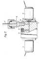
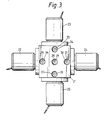
- the solvent proportioning valve arrangement 9 is shown in Figures 2 and 3, and comprises a block 21 on which are mounted four solenoids 22,23,24 and 25 which operate respective diaphragms one of which is shown in Figure 2 and referenced 26.
- each of the solenoids operates a similar device.
- the valve outputs are commoned within the block 21 in a cross shaped tube 27 which feds a common upright tube 28.
- the tube 28 communicates with outlet means 29 which comprises a screw-threaded recess.
- the outlet means 29 is arranged so that a connecting tube with a connector on the end can be screwed into the outlet 29, the other end of the tube having a similar connection into the inlet of the pump.
- all the outlet ports from the valves are commoned to a single outlet means 29.
- the inlet means to each valve comprises a tube 30 and a recess 31 which communicates with the tube and which is screw-threaded to receive a chamber 32.
- a chamber 32 For the sake of simplicity only one such chamber and one such valve are shown in Figure 2, but it can be seen from Figure 3 that there is a respective valve inlet for each valve, each of which contain an inlet means for mounting such a chamber. These are referenced on Figure 3 as items 33 to 38. Thus it is ensured that the chambers one of which is shown as item 32 are located close to the inlet ports of the valves.
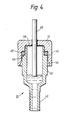
- the chamber 32 is shown in greater detail in Figure 4 and comprises a body portion 40 and a cap portion 41.
- the body and cap portions are both circular in section.
- the body portion 40 has a screw-threaded projecting portion 42 which is arranged to mate with the inlet means 31,33,35 and 37 of the valves in the valve block 21.
- the cap portion 41 has a tube 43 which passes through the cap portion into the interior of the chamber when the cap is assembled onto the body portion, the tube 43 being brazed into an aperture in the cap 41.
- the internal wall of the cap portion 41 has at its opening an inclined portion 43 which tapers inwardly from the free end of the wall until it meets a parallel section 45.
- the wall of the body portion 40 includes a step 46 on which an O-ring 47 is located.
- the O-ring 47 seals the gap between the body portion and the cap portion when the cap is assembled onto the body portion so that an enclosed chamber 48 is formed which contains either air or a gas or a mixture of gases.
- an enclosed chamber 48 is formed which contains either air or a gas or a mixture of gases.
- valves need not be solenoid operated but could for example be pneumatically operated valves.
- the choice of valve will depend on the operating speed required, the reliability, cost, and ease of control for any particular application.
- the chamber 32 may be constructed in alternative ways.
- the cap for example could be connected to the body portion by a screw-thread but it is necessary to ensure that a volume of air or other gas is trapped within the chamber. It is not necessary that a two part construction for the chamber is used provided that it can be ensured that a volume of air is retained within the chamber.
- the number of valves provided will depend on the number solvents which it is desired to mix together and while four have been shown in this application any convenient number may be provided.
- valves round a single block provides a compact construction minimising the liquid volume between the outlets of the valve and the inlet to the pump, but other constructions could be devised which would prove satisfactory under certain system requirements. If the volume of liquid between the pump and valve outlet is not critical then a side by side arrangement of valves with a longer connecting tube from the outlets of the valves to the pump inlet may be satisfactory.
Landscapes
- Physics & Mathematics (AREA)
- Health & Medical Sciences (AREA)
- Life Sciences & Earth Sciences (AREA)
- Chemical & Material Sciences (AREA)
- Analytical Chemistry (AREA)
- Biochemistry (AREA)
- General Health & Medical Sciences (AREA)
- General Physics & Mathematics (AREA)
- Immunology (AREA)
- Pathology (AREA)
- Sampling And Sample Adjustment (AREA)
- Treatment Of Liquids With Adsorbents In General (AREA)
Applications Claiming Priority (2)
| Application Number | Priority Date | Filing Date | Title |
|---|---|---|---|
| GB8622328A GB2195266B (en) | 1986-09-17 | 1986-09-17 | Liquid chromatograph apparatus including a proportioning arrangement. |
| GB8622328 | 1986-09-17 |
Publications (2)
| Publication Number | Publication Date |
|---|---|
| EP0260761A2 true EP0260761A2 (fr) | 1988-03-23 |
| EP0260761A3 EP0260761A3 (fr) | 1990-04-25 |
Family
ID=10604290
Family Applications (1)
| Application Number | Title | Priority Date | Filing Date |
|---|---|---|---|
| EP87201759A Withdrawn EP0260761A3 (fr) | 1986-09-17 | 1987-09-15 | Appareil de chromatographie en liquides |
Country Status (5)
| Country | Link |
|---|---|
| US (1) | US4879029A (fr) |
| EP (1) | EP0260761A3 (fr) |
| JP (1) | JPS6378065A (fr) |
| AU (1) | AU598030B2 (fr) |
| GB (1) | GB2195266B (fr) |
Cited By (2)
| Publication number | Priority date | Publication date | Assignee | Title |
|---|---|---|---|---|
| WO2006029017A1 (fr) * | 2004-09-03 | 2006-03-16 | Symyx Technologies, Inc. | Systeme et procede de chromatographie rapide a regulation de temperature de fluide et de composition en phase mobile |
| WO2015062888A2 (fr) | 2013-10-30 | 2015-05-07 | Saltel Industries | Chemise metallique expansible et dispositif qui en fait usage |
Families Citing this family (13)
| Publication number | Priority date | Publication date | Assignee | Title |
|---|---|---|---|---|
| US5089124A (en) * | 1990-07-18 | 1992-02-18 | Biotage Inc. | Gradient generation control for large scale liquid chromatography |
| US5275723A (en) * | 1992-07-06 | 1994-01-04 | Sp Industries Ltd. Partnership | Mobile phase reservoir |
| US5397467A (en) * | 1993-08-12 | 1995-03-14 | Kontes Glass Company | Liquid chromatography system and reservoir cap for use therein |
| GB9403911D0 (en) * | 1994-03-01 | 1994-04-20 | Univ Manchester | Porous films |
| DE19531811A1 (de) * | 1995-08-30 | 1997-03-06 | Bosch Gmbh Robert | Kraftstoffeinspritzpumpe |
| US6956324B2 (en) | 2000-08-04 | 2005-10-18 | Semiconductor Energy Laboratory Co., Ltd. | Semiconductor device and manufacturing method therefor |
| AU2002211389A1 (en) * | 2000-10-03 | 2002-04-15 | California Institute Of Technology | Microfluidic devices and methods of use |
| US6743356B1 (en) * | 2000-10-27 | 2004-06-01 | Johnson & Johnson | High throughput high performance chromatography system |
| EP1376121A1 (fr) * | 2002-06-29 | 2004-01-02 | Agilent Technologies Inc. a Delaware Corporation | Dispositif de pompage |
| US8961783B2 (en) | 2008-09-12 | 2015-02-24 | Waters Technologies Corporation | Apparatus and methods for preparative liquid chromatography |
| DE102017124618B4 (de) * | 2017-10-20 | 2019-07-11 | Dionex Softron Gmbh | Verbindungen von Kapillaren, insbesondere für HPLC |
| GB201820690D0 (en) * | 2018-12-19 | 2019-01-30 | Ge Healthcare Bio Sciences Ab | Device for distributing a flow |
| GB201820691D0 (en) * | 2018-12-19 | 2019-01-30 | Ge Healthcare Bio Sciences Ab | Device for distributing a flow |
Family Cites Families (22)
| Publication number | Priority date | Publication date | Assignee | Title |
|---|---|---|---|---|
| FR7920E (fr) * | 1906-06-07 | 1907-11-23 | Alexis Pierre Bellemere | Appareil évitant les coups de bélier dans les distributions d'eau |
| US1364680A (en) * | 1920-02-03 | 1921-01-04 | Archilles A Barton | Discharge t for pumps |
| US1553768A (en) * | 1922-04-18 | 1925-09-15 | Frederick H Gleason | Means for measuring and delivering volumes of fluid |
| US1774095A (en) * | 1927-09-17 | 1930-08-26 | Firm Alex Friedmann | Viscose or rayon pump |
| US1777891A (en) * | 1928-11-16 | 1930-10-07 | Stewart Warner Corp | Pressure-trapping chamber for fuel pumps |
| US2915185A (en) * | 1958-01-08 | 1959-12-01 | Airtex Products Inc | Air dome and magnetic filter to automotive fuel pump lines |
| DE1600621A1 (de) * | 1967-01-26 | 1970-01-08 | Teves Gmbh Alfred | Hydropneumatischer Druckspeicher mit einem zweiteiligen druckfesten Gehaeuse |
| US3669150A (en) * | 1970-03-19 | 1972-06-13 | American Air Filter Co | Hydrodynamic surge absorbing apparatus |
| JPS51114194A (en) * | 1975-04-01 | 1976-10-07 | Showa Denko Kk | Device for protection of liquid chromatographs |
| US4128476A (en) * | 1977-06-14 | 1978-12-05 | Spectra-Physics, Inc. | Carrier composition control for liquid chromatographic systems |
| US4116046A (en) * | 1977-08-05 | 1978-09-26 | Hoffmann-La Roche Inc. | Liquid chromatography system |
| US4177016A (en) * | 1978-04-17 | 1979-12-04 | Bechtel International Corporation | Self cleaning manifold connection for slurry pump |
| FR2427543A1 (fr) * | 1978-06-02 | 1979-12-28 | Varian Associates | Amortisseur de pulsations pour dispositif de pompage de liquide, notamment pour installation de chromatographie en phase liquide |
| FR2445902A1 (fr) * | 1979-01-02 | 1980-08-01 | Magnussen Haakon Jun | Ensemble de pompage a surcompression pour chromatographie en phase liquide |
| US4222414A (en) * | 1979-06-14 | 1980-09-16 | Varian Associates, Inc. | Pulse damper for high-pressure liquid chromatography |
| US4496245A (en) * | 1983-03-07 | 1985-01-29 | International Business Machines Corporation | Liquid chromatography proportioning valve and mixer |
| JPS60155091A (ja) * | 1984-01-25 | 1985-08-14 | アルバツクサ−ビス株式会社 | 流体用微小流量調節器 |
| US4595496A (en) * | 1984-06-29 | 1986-06-17 | Millipore Corporation | Liquid composition control |
| US4541452A (en) * | 1984-10-10 | 1985-09-17 | The Perkin-Elmer Corporation | Solvent pressurization system |
| US4591442A (en) * | 1984-11-26 | 1986-05-27 | Nelson Research & Development Co. | Flash chromatography |
| US4595495A (en) * | 1985-02-22 | 1986-06-17 | Eldex Laboratories, Inc. | Programmable solvent delivery system and process |
| DE8517883U1 (de) * | 1985-06-20 | 1985-08-01 | Bombe, Sigwart, 7968 Saulgau | Pulsationsdämpfer für nicht pulsationsfrei fördernde Flüssigkeitspumpen |
-
1986
- 1986-09-17 GB GB8622328A patent/GB2195266B/en not_active Expired - Lifetime
-
1987
- 1987-09-15 EP EP87201759A patent/EP0260761A3/fr not_active Withdrawn
- 1987-09-15 AU AU78401/87A patent/AU598030B2/en not_active Ceased
- 1987-09-17 JP JP62231211A patent/JPS6378065A/ja active Pending
-
1989
- 1989-04-18 US US07/339,938 patent/US4879029A/en not_active Expired - Fee Related
Cited By (2)
| Publication number | Priority date | Publication date | Assignee | Title |
|---|---|---|---|---|
| WO2006029017A1 (fr) * | 2004-09-03 | 2006-03-16 | Symyx Technologies, Inc. | Systeme et procede de chromatographie rapide a regulation de temperature de fluide et de composition en phase mobile |
| WO2015062888A2 (fr) | 2013-10-30 | 2015-05-07 | Saltel Industries | Chemise metallique expansible et dispositif qui en fait usage |
Also Published As
| Publication number | Publication date |
|---|---|
| AU7840187A (en) | 1988-03-24 |
| US4879029A (en) | 1989-11-07 |
| JPS6378065A (ja) | 1988-04-08 |
| GB2195266B (en) | 1990-06-20 |
| AU598030B2 (en) | 1990-06-14 |
| GB8622328D0 (en) | 1986-10-22 |
| EP0260761A3 (fr) | 1990-04-25 |
| GB2195266A (en) | 1988-04-07 |
Similar Documents
| Publication | Publication Date | Title |
|---|---|---|
| US4879029A (en) | Liquid chromatograph apparatus | |
| US8048312B2 (en) | Separation analyzer | |
| CN107449851B (zh) | 利用流体驱动单元与样品容纳空间之间的流体连接进行样品注入 | |
| US3934456A (en) | Solvent gradient generator for chromatography systems | |
| US7959801B2 (en) | Device for generating micro- and nanoflow mobile phase gradients for high-performance liquid chromatography | |
| US12055526B2 (en) | Sample handling and dispatching individual sample packages for fluid processing | |
| US12078619B2 (en) | Injector serving multiple sample separation apparatuses | |
| US20240060939A1 (en) | Sample metering and injection for liquid chromatography | |
| EP4007915B1 (fr) | Traitement de fluide avec modulation de soutirage-transfert | |
| US5862832A (en) | Gradient proportioning valve | |
| US4902414A (en) | Liquid chromatograph apparatus | |
| EP1856518B1 (fr) | Dispositif de régulation de fluide à limiteur variable | |
| GB2591435A (en) | Sample injection in a combined chromatography system | |
| Trisciani et al. | Evaluation of a microHPLC system dedictaed to packed capillary column liquid chromatography | |
| WO2003102573A1 (fr) | Procede et dispositif pour partialiser un echantillon gazeux dans une introduction chromatographique | |
| WO2022243867A2 (fr) | Raccordement fluidique de trajets d'échantillonnage et de séparation | |
| Andreolini et al. | Gradient elution system for packed capillary column liquid chromatography | |
| Bombaugh | The Use of HPLC for Water Analysis | |
| WO2020109838A1 (fr) | Élimination de parties de composition indéfinie de la phase mobile | |
| HU185579B (en) | Sample feeding system for liquid chromatography |
Legal Events
| Date | Code | Title | Description |
|---|---|---|---|
| PUAI | Public reference made under article 153(3) epc to a published international application that has entered the european phase |
Free format text: ORIGINAL CODE: 0009012 |
|
| AK | Designated contracting states |
Kind code of ref document: A2 Designated state(s): CH DE FR GB IT LI NL SE |
|
| RAP3 | Party data changed (applicant data changed or rights of an application transferred) |
Owner name: N.V. PHILIPS' GLOEILAMPENFABRIEKEN Owner name: PHILIPS ELECTRONIC AND ASSOCIATED INDUSTRIES LIMIT |
|
| PUAL | Search report despatched |
Free format text: ORIGINAL CODE: 0009013 |
|
| AK | Designated contracting states |
Kind code of ref document: A3 Designated state(s): CH DE FR GB IT LI NL SE |
|
| 17P | Request for examination filed |
Effective date: 19901023 |
|
| RAP3 | Party data changed (applicant data changed or rights of an application transferred) |
Owner name: N.V. PHILIPS' GLOEILAMPENFABRIEKEN Owner name: PHILIPS ELECTRONICS UK LIMITED |
|
| 17Q | First examination report despatched |
Effective date: 19920410 |
|
| STAA | Information on the status of an ep patent application or granted ep patent |
Free format text: STATUS: THE APPLICATION IS DEEMED TO BE WITHDRAWN |
|
| 18D | Application deemed to be withdrawn |
Effective date: 19920821 |
|
| RIN1 | Information on inventor provided before grant (corrected) |
Inventor name: WHITEHEAD, MARTIN ALAN |