EP0260885B1 - Gyroscope optique à fibre double - Google Patents
Gyroscope optique à fibre double Download PDFInfo
- Publication number
- EP0260885B1 EP0260885B1 EP87308042A EP87308042A EP0260885B1 EP 0260885 B1 EP0260885 B1 EP 0260885B1 EP 87308042 A EP87308042 A EP 87308042A EP 87308042 A EP87308042 A EP 87308042A EP 0260885 B1 EP0260885 B1 EP 0260885B1
- Authority
- EP
- European Patent Office
- Prior art keywords
- polarisation
- fiber
- maintaining
- optical fiber
- principal axes
- Prior art date
- Legal status (The legal status is an assumption and is not a legal conclusion. Google has not performed a legal analysis and makes no representation as to the accuracy of the status listed.)
- Expired - Lifetime
Links
- 239000000835 fiber Substances 0.000 title claims description 247
- 230000009977 dual effect Effects 0.000 title description 18
- 239000013307 optical fiber Substances 0.000 claims description 88
- 230000003287 optical effect Effects 0.000 claims description 84
- 239000000758 substrate Substances 0.000 claims description 51
- 238000000034 method Methods 0.000 claims description 26
- GQYHUHYESMUTHG-UHFFFAOYSA-N lithium niobate Chemical compound [Li+].[O-][Nb](=O)=O GQYHUHYESMUTHG-UHFFFAOYSA-N 0.000 claims description 8
- 230000005540 biological transmission Effects 0.000 claims 2
- 230000010287 polarization Effects 0.000 description 150
- 230000008878 coupling Effects 0.000 description 31
- 238000010168 coupling process Methods 0.000 description 31
- 238000005859 coupling reaction Methods 0.000 description 31
- VYPSYNLAJGMNEJ-UHFFFAOYSA-N silicon dioxide Inorganic materials O=[Si]=O VYPSYNLAJGMNEJ-UHFFFAOYSA-N 0.000 description 27
- 238000005253 cladding Methods 0.000 description 25
- 239000000463 material Substances 0.000 description 23
- 230000005684 electric field Effects 0.000 description 21
- 239000013598 vector Substances 0.000 description 17
- YBMRDBCBODYGJE-UHFFFAOYSA-N germanium dioxide Chemical compound O=[Ge]=O YBMRDBCBODYGJE-UHFFFAOYSA-N 0.000 description 16
- 239000013078 crystal Substances 0.000 description 12
- 230000003993 interaction Effects 0.000 description 12
- 230000001902 propagating effect Effects 0.000 description 12
- 235000012239 silicon dioxide Nutrition 0.000 description 12
- 239000000377 silicon dioxide Substances 0.000 description 11
- 229920002120 photoresistant polymer Polymers 0.000 description 10
- 238000009826 distribution Methods 0.000 description 9
- 229910052681 coesite Inorganic materials 0.000 description 8
- 229910052906 cristobalite Inorganic materials 0.000 description 8
- 238000004519 manufacturing process Methods 0.000 description 8
- 229910052682 stishovite Inorganic materials 0.000 description 8
- 229910052905 tridymite Inorganic materials 0.000 description 8
- 230000008033 biological extinction Effects 0.000 description 6
- 239000000382 optic material Substances 0.000 description 6
- 239000010936 titanium Substances 0.000 description 6
- 230000007704 transition Effects 0.000 description 6
- RTAQQCXQSZGOHL-UHFFFAOYSA-N Titanium Chemical compound [Ti] RTAQQCXQSZGOHL-UHFFFAOYSA-N 0.000 description 5
- 230000008859 change Effects 0.000 description 5
- 239000011521 glass Substances 0.000 description 5
- 230000028161 membrane depolarization Effects 0.000 description 5
- 230000000644 propagated effect Effects 0.000 description 5
- 229910052719 titanium Inorganic materials 0.000 description 5
- 230000008901 benefit Effects 0.000 description 3
- 230000001419 dependent effect Effects 0.000 description 3
- 239000005350 fused silica glass Substances 0.000 description 3
- 230000008569 process Effects 0.000 description 3
- CSCPPACGZOOCGX-UHFFFAOYSA-N Acetone Chemical compound CC(C)=O CSCPPACGZOOCGX-UHFFFAOYSA-N 0.000 description 2
- 239000000853 adhesive Substances 0.000 description 2
- 230000001070 adhesive effect Effects 0.000 description 2
- 230000015572 biosynthetic process Effects 0.000 description 2
- 230000001427 coherent effect Effects 0.000 description 2
- 238000006880 cross-coupling reaction Methods 0.000 description 2
- 239000003989 dielectric material Substances 0.000 description 2
- 230000000694 effects Effects 0.000 description 2
- 238000005562 fading Methods 0.000 description 2
- 238000010438 heat treatment Methods 0.000 description 2
- 229910052751 metal Inorganic materials 0.000 description 2
- 239000002184 metal Substances 0.000 description 2
- 238000005498 polishing Methods 0.000 description 2
- 239000010453 quartz Substances 0.000 description 2
- ZOXJGFHDIHLPTG-UHFFFAOYSA-N Boron Chemical compound [B] ZOXJGFHDIHLPTG-UHFFFAOYSA-N 0.000 description 1
- 229910003327 LiNbO3 Inorganic materials 0.000 description 1
- 238000004026 adhesive bonding Methods 0.000 description 1
- 229910052782 aluminium Inorganic materials 0.000 description 1
- XAGFODPZIPBFFR-UHFFFAOYSA-N aluminium Chemical compound [Al] XAGFODPZIPBFFR-UHFFFAOYSA-N 0.000 description 1
- 229910052796 boron Inorganic materials 0.000 description 1
- 239000004568 cement Substances 0.000 description 1
- 239000011248 coating agent Substances 0.000 description 1
- 238000000576 coating method Methods 0.000 description 1
- 230000007423 decrease Effects 0.000 description 1
- 238000000151 deposition Methods 0.000 description 1
- 230000008021 deposition Effects 0.000 description 1
- 238000009792 diffusion process Methods 0.000 description 1
- 239000006185 dispersion Substances 0.000 description 1
- 239000002019 doping agent Substances 0.000 description 1
- 230000005672 electromagnetic field Effects 0.000 description 1
- 239000003822 epoxy resin Substances 0.000 description 1
- 230000008020 evaporation Effects 0.000 description 1
- 238000001704 evaporation Methods 0.000 description 1
- 238000002839 fiber optic waveguide Methods 0.000 description 1
- 239000008246 gaseous mixture Substances 0.000 description 1
- 229940119177 germanium dioxide Drugs 0.000 description 1
- 230000009477 glass transition Effects 0.000 description 1
- 238000000227 grinding Methods 0.000 description 1
- 230000006698 induction Effects 0.000 description 1
- 150000002500 ions Chemical class 0.000 description 1
- 238000007620 mathematical function Methods 0.000 description 1
- 238000005259 measurement Methods 0.000 description 1
- 230000008018 melting Effects 0.000 description 1
- 238000002844 melting Methods 0.000 description 1
- 238000002156 mixing Methods 0.000 description 1
- 238000007500 overflow downdraw method Methods 0.000 description 1
- 230000001590 oxidative effect Effects 0.000 description 1
- 230000010363 phase shift Effects 0.000 description 1
- 238000007540 photo-reduction reaction Methods 0.000 description 1
- 229920000647 polyepoxide Polymers 0.000 description 1
- 238000012545 processing Methods 0.000 description 1
- 230000004044 response Effects 0.000 description 1
- 230000000717 retained effect Effects 0.000 description 1
- 239000002904 solvent Substances 0.000 description 1
- 238000004544 sputter deposition Methods 0.000 description 1
- 238000010561 standard procedure Methods 0.000 description 1
- 238000009827 uniform distribution Methods 0.000 description 1
Images


Classifications
-
- G—PHYSICS
- G01—MEASURING; TESTING
- G01C—MEASURING DISTANCES, LEVELS OR BEARINGS; SURVEYING; NAVIGATION; GYROSCOPIC INSTRUMENTS; PHOTOGRAMMETRY OR VIDEOGRAMMETRY
- G01C19/00—Gyroscopes; Turn-sensitive devices using vibrating masses; Turn-sensitive devices without moving masses; Measuring angular rate using gyroscopic effects
- G01C19/58—Turn-sensitive devices without moving masses
- G01C19/64—Gyrometers using the Sagnac effect, i.e. rotation-induced shifts between counter-rotating electromagnetic beams
- G01C19/72—Gyrometers using the Sagnac effect, i.e. rotation-induced shifts between counter-rotating electromagnetic beams with counter-rotating light beams in a passive ring, e.g. fibre laser gyrometers
Definitions
- This invention relates generally to rotation sensors and particularly to fiber optic rotation sensors. Still more particularly, this invention relates to fiber optic rotation sensors including polarization maintaining optical fiber.
- a fiber optic ring interferometer typically comprises a loop of fiber optic material that guides counter-propagating light waves. After traversing the loop, the counter-propagating waves are combined so that they constructively or destructively interfere to form an optical output signal. The intensity of the optical output signal varies as a function of the interference, which is dependent upon the relative phase of the counter-propagating waves.
- Fiber optic ring interferometers have proven to be particularly useful for rotation sensing. Rotation of the loop creates a relative phase difference between the counter-propagating waves in accordance with the well known Sagnac effect. The amount of phase difference is a function of the angular velocity of the loop.
- the optical output signal produced by the interference of the counter-propagating waves varies in intensity as a function of the rotation rate of the loop. Rotation sensing is accomplished by detecting the optical output signal and processing it to determine the rotation rate.
- a rotation sensor In order to be suitable for inertial navigation applications, a rotation sensor must have a very wide dynamic range.
- the rotation sensor must be capable of detecting rotation rates as low as 0.01 degrees per hour and as high as 1,000 degrees per second.
- the ratio of the upper limit to lower limit to be measured is approximately 109.
- An optical fiber comprises a central core and a surrounding cladding.
- the refractive index of the cladding is greater than that of the core.
- the diameter of the core is so small that light incident upon the core-cladding interface remains in the core by internal reflections.
- a light wave may be represented by a time-varying electromagnetic field comprising orthogonal electric and magnetic field vectors having a frequency equal to the frequency of the light wave.
- An electromagnetic wave propagating through a guiding structure can be described by a set of normal modes.
- the normal modes are the permissible distributions of the electric and magnetic fields within the guiding structure, for example, a fiber optic waveguide.
- the field distributions are directly related to the distribution of energy within the structure.
- the normal modes are generally represented by mathematical functions that describe the field components in the wave in terms of the frequency and spatial distribution in the guiding structure. The specific functions that describe the normal modes of a waveguide depend upon the geometry of the waveguide.
- the guided wave is confined to a structure having a circular cross section of fixed dimensions
- only fields having certain frequencies and spatial distributions will propagate without severe attenuation.
- the waves having field components that propagate with low attenuation are called normal modes.
- a single mode fiber will propagate only one spatial distribution of energy, that is, one normal mode, for a signal of a given frequency.
- the wave is a transverse electric (TE) mode. If only the magnetic field vector is perpendicular to to the optic axis, the wave is a transverse magnetic (TM) mode. If both the electric and magnetic field vectors are perpendicular to the optic axis, then the wave is a transverse electromagnetic (TEM) mode.
- TE transverse electric
- TM transverse magnetic
- TEM transverse electromagnetic
- the electric field may be in any direction that is perpendicular to the optic axis.
- the direction of the electric field vector in an electromagnetic wave is the polarization of the wave.
- a wave will have random polarization in which there is a uniform distribution of electric field vectors pointing in all directions permissible for a given mode. If all the electric field vectors in a wave point in only a particular direction, the wave is linearly polarized.
- the electric field consists of two orthogonal electric field components of equal magnitude phase shifted by 90 degrees from each other, the electric field is circularly polarized, because the net electric field is a vector that rotates around the propagation direction at an angular velocity equal to the frequency of the wave.
- the two linear polarizations are unequal or phased other than 90 degrees from each other, the wave has elliptical polarization.
- any arbitrary polarization can be represented by the sum of two orthogonal linear polarizations, two oppositely directed circular polarizations or two counter rotating elliptical polarizations that have orthogonal major axes.
- the boundary between the core and cladding is a dielectric interface at which certain well-known boundary conditions on the field components must be satisfied.
- the component of the electric field parallel to the interface must be continuous.
- a single mode optical fiber propagates electromagnetic energy having an electric field component perpendicular to the core-cladding interface. Since the fiber core has an index of refraction greater than that of the cladding and light impinges upon the interface at angles greater than or equal to the critical angle, essentially all of the electric field remains in the core by internal reflection at the interface.
- the radial electric field component in the cladding must be a rapidly decaying exponential function. An exponentially decaying electric field is usually called the evanescent field.
- the velocity of an optical signal depends upon the index of refraction of the medium through which the light propagates. Certain materials have different refractive indices for different polarizations. A material that has two refractive indices is said to be birefringent.
- the polarization of the signal propagating along a single mode optical fiber is sometimes referred to as a mode.
- a standard single mode optical fiber may be regarded as a two mode fiber because it will propagate two waves of the same frequency and spatial distribution that have two different polarizations. Two different polarization components of the same normal mode can propagate through a birefringent material unchanged except for a velocity difference between the two polarizations.
- Circular birefringence, linear birefringence, and elliptical birefringence are each described with reference to different polarization modes. If a material exhibits circular birefringence, the polarization of a light wave is expressed as a combination of two counter-rotating components. One of the circular polarizations is referred to as "right-hand circular” while the other is referred to as "left-hand circular”. In a non-birefringent material both right hand and left hand circular polarizations travel at the same velocity. The counterrotating electric field vectors of the circularly polarized components of the light represent the polarization modes for circular birefringence.
- the circular polarization vectors are in phase with one another and are of equal amplitude. If the light is elliptically polarized, the circular polarization vectors are of unequal amplitudes or phase. In general, elliptically polarized light may have varying degrees of ellipticity; and the polarization may range from linearly polarized at one extreme to circularly polarized at the other extreme.
- the velocity of propagation of one circular polarization vector is greater than the velocity of propagation of the counterrotating polarization vector.
- the propagation velocity of the light in one of the linearly polarized modes is greater than the propagation velocity of the light in the other normal linearly polarized mode.
- Elliptical birefringence results when both linear birefringence and circular birefringence exist at a point in a material through which the light wave is propagating.
- the elliptical birefringence affects the polarization of light in a complex manner which depends, in part, upon the relative magnitudes of the linear birefringence and the circular birefringence.
- any polarized light can be represented by two circularly polarized waves having proper phase and amplitude; two elliptically rotating components or two perpendicular linearly polarized electric field components.
- a linear polarization state in a fiber optic rotation sensor is typically achieved with some type of linear polarizer such as the fiber optic polarizer described in U.S. Patent No. 4,386,822 to Bergh.
- the polarization state input to the polarizer is arbitrary in general.
- the polarizer couples light of undesired polarizations out of the fiber and permits light having only a selected desired polarization to propagate through the fiber.
- Bergh discloses a fiber optic polarizer including a length of optical fiber mounted in a curved groove in a quartz substrate. The substrate and a portion of the optical fiber are ground and polished to remove a portion of the cladding from the fiber to form an interaction region. The portion of the fiber in the groove is convexly curved as viewed toward the polished surface.
- the birefringent crystal mounted on the substrate over the interaction region in close proximity to the core of the fiber optic material.
- the crystal is positioned to partially intersect the path of light propagating in the optical fiber so that evanescent field coupling couples light of undesired polarizations from the optical fiber into the crystal.
- Bias error is the primary source of error in using fiber optic Sagnac rings as rotation sensors.
- the bias of a rotation sensor is the signal output when there is no signal input. If the bias is constant, then it may be subtracted from the output signal when there is a signal input to determine the response of the rotation sensor to the input signal. However, the bias does not remain constant over time and temperature variations.
- the principal source of bias error in fiber gyroscopes results from an imperfect polarizer and polarization cross coupling in the fiber.
- An ideal polarizer should have an infinite extinction ratio.
- the extinction ratio of a polarizer is the ratio of the intensity of the undesired polarization in the output signal to its intensity in the input signal. This error source was first identified by Kintner, Opt. Lett., Vol. 6, No. 3, p. 154 (1981). Polarization instability manifests itself in optical interferometric systems in a manner analogous to signal fading in classical communications systems.
- Fiber optic gyroscopes operating with polarized light require polarizers having extinction ratios in excess of 100 dB to keep bias errors below 0.01 deg/hr.
- Previous fiber optic gyroscopes using unpolarized light require extinction ratios in the 60-100 dB range and require the use of high quality polarization maintaining (PM) fiber throughout the gyroscope.
- PM fiber in fiber optic gyroscopes are reduced polarizer extinction ratio requirements and reduced bias error due to the Faraday effect. It is also necessary to use active polarization control when PM fiber is used to form the gyroscope. However, PM fiber is so expensive that it is impractical to use it throughout a fiber optic gyroscope.
- Tai et al. Electronics Letters, Vol. 22, No. 10, May 1986, pages 546-547 discloses an all-fibre gyroscope that includes a length of optical fiber formed in a sensing loop and an optical signal Source in the form of a superluminescent diode for providing light to the sensing loop.
- Tai et al. further discloses a depolariser for providing an unpolarized optical clockwise beam and an upolarised counterclockwise beam and a phase modulator for modulating a predetermined polarization component.
- the gyroscope of Tai et al. also includes a coil of non-polarization maintaining optical fiber that forms a sensing coil and a detector for detecting interference between the clockwise and counterclockwise beams.
- UK Patent Appln. GB-A-2089976 discloses a fiber optic ring interferometer that includes a light source, a pair of beamsplitters and a pair of depolarisers arranged to provide unpolarised light signals to form counterpropagating waves in the fiber optic ring.
- the present invention provides a Sagnac ring rotation sensor as defined in Claim 1, and a method of using such a sensor, as defined in Claim 4.
- the present invention overcomes both the difficulties of signal fading in fiber optic rotation sensors and the cost of using polarization maintaining fiber throughout a rotation sensor.
- a preferred embodiment of the invention includes a polarization-maintaining module which reduces polarizer extinction ratio requirements and eliminates the necessity of using active polarization control.
- This dual fiber gyroscope further includes a sensing coil formed of ordinary single mode fiber, which is much less expensive than the polarization maintaining fiber used in the module.
- the Sagnac ring rotation sensor embodying the invention includes an optical signal source and a polarization maintaining module arranged to receive signals from the optical signal source.
- the invention provides unpolarized clockwise (CW) and counterclockwise (CCW) beams to the sensing coil.
- the polarization maintaining module includes means for providing a first polarized optical beam and a second unpolarized beam to a Sagnac ring.
- the first and second beams may be designated as CW and CCW, respectively.
- the sensor also includes means for modulating a predetermined polarization component of each beam.
- a coil of non-polarization maintaining optical fiber forming the Sagnac ring guides the polarized CW beam and the unpolarized CCW beam around a closed path so that rotations of the sensing coil change the interterence pattern between the beams.
- a detector produces an electrical signal indicative of changes in the interference pattern to indicate rotation of the coil.
- the Sagnac ring rotation sensor embodying the invention also comprises a length of a first polarization maintaining optical fiber having a pair of principal axes.
- the rotation sensor further includes means for providing an optical signal to the first polarization maintaining optical fiber.
- the optical signal has a first linear polarization component parallel to one of the principal axes of the first polarization maintaining optical fiber and a second linear polarization component parallel to the other principle axis.
- a first polarizer passes light polarized along a polarization axis oriented at a 45° angle to the principal axes of the first polarization maintaining optical fiber and attenuates other polarizations.
- An optical coupler couples optical signals between the first polarization maintaining optical fiber and a length of a second polarization maintaining fiber.
- the second polarization maintaining fiber has principal axes that are parallel to the principal axes of the first polarization maintaining optical fiber.
- Light coupled into the second polarization maintaining fiber forms a counterclockwise beam and light remaining in first polarization maintaining optical fiber forms a clockwise beam.
- a third length of polarization maintaining optical fiber is connected between an optical waveguide and the sensing coil.
- the optical waveguide is positioned to guide signals between the second polarization maintaining fiber and the third polarization maintaining fiber.
- the optical waveguide has principal axes oriented at an angle of 45° to the principal axes of the second and third polarization maintaining fibers.
- the phase of light of a predetermined polarization in the optical waveguide is modulated by a phase modulator placed between a pair of polarizers.
- the polarizers make the polarizations of the clockwise and counterclockwise beams in the optical waveguide have the predetermined polarization before they reach the phase modulator.
- the optical waveguide is preferably formed in a substrate of lithium niobate and the phase modulator electrodes and adjacent polarizers are preferably positioned over the optical waveguide with the phase modulator between the polarizers.
- the method for using such a Sagnac ring rotation sensor comprises the steps of introducing signals from the optical signal source into a polarization maintaining module and producing unpolarized clockwise and counterclockwise beams and an unpolarized counterclockwise beam output from the polarization maintaining module.
- the method further includes modulating a predetermined polarization component of light in the polarization maintaining module and connecting a coil of non-polarization maintaining optical fiber to the polarization maintaining module to receive the unpolarized optical clockwise beam and the unpolarized counterclockwise beam.
- the polarization maintaining module may include a length of a first polarization maintaining optical fiber having a pair of principal axes.
- the optical signal is then provided to the first polarization maintaining optical fiber.
- the optical signal has a first linear polarization component parallel to one of the principal axes of the first polarization maintaining optical fiber and a second linear polarization component parallel to the other principle axis.
- the method may also include placing a first polarizer that passes light polarized along a first polarization axis and attenuates other polarizations adjacent the first length of polarization maintaining optical fiber with the first polarization axis oriented at a 45° angle to the principal axes of the first polarization maintaining optical fiber.
- the method may also include coupling optical signals between the first polarization maintaining optical fiber and a length of a second polarization maintaining fiber.
- the second polarization maintaining fiber has principal axes that are parallel to the principal axes of the first polarization maintaining optical fiber.
- Light coupled into the second polarization maintaining fiber forms a counterclockwise beam and light remaining in first polarization maintaining optical fiber forms a clockwise beam in the sensing coil.
- the method further include coupling signals from the second polarization maintaining fiber into an optical waveguide having principal axes oriented at an angle of 45° to the principal axes of the second and third polarization maintaining fiber. Signals are coupled from the optical waveguide into a third length of polarization maintaining optical fiber.
- the method further includes modulating the phase of light having a predetermined polarization in the optical waveguide.
- the method may further include polarizing the counterclockwise beam in the optical waveguide such that signals incident upon the phase modulator from the second polarization maintaining fiber have the predetermined polarization; a loop of optical fiber being connected between the optical waveguide and the first polarization maintaining optical fiber to provide a sensing coil for the clockwise beam and the counterclockwise beam; and polarizing the clockwise beam in the optical waveguide such that signals incident upon the phase modulator from the sensing coil have the predetermined polarization.
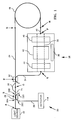
- a dual fiber optic gyroscope 20 includes a light source 22, which is preferably a superluminescent diode (SLD) that emits coherent light.
- the optical output of the light source 22 is input to a PM optical fiber 24 at point A .
- the optical fiber 24 is preferably a single mode optical fiber.
- Light input to the fiber 24 then propagates to an optical coupler 28 located at point B in Figure 1.
- the coupler 28 couples a portion of the optical signal incident thereon into a PM optical fiber 29.
- Light remaining in the fiber 24 is incident upon a linear polarizer 30 located at point C .
- the optical coupler couples a first portion of the light into a PM optical fiber 34.
- the light coupled into the fiber 34 forms the counterclockwise beam for the dual fiber optic gyroscope 20.
- Light that remains in the fiber 24 forms the clockwise beam for the dual fiber optic gyroscope 20.
- the fiber 34 guides the counterclockwise beam to module 35.
- the module 35 includes a substrate 36 that preferably comprises a lithium niobate chip.
- An integrated optics waveguide 38 shown in Figures 1, 9 and 10 and is coupled to the fiber 34 at point E to transmit optical signals therebetween.
- a phase modulator 42 is formed on the lithium niobate chip 38 between a pair of polarizers 44 and 46.
- a length of PM fiber 48 is mounted adjacent the integrated optics waveguide 38.
- a sensing coil 49 has an end 49A connected to the fiber 34 at point G and an end 49B connected to the PM fiber 48 at point H .
- the sensing coil preferably includes about 1 km of single mode optical fiber.
- the connections at point G and H are preferably reflectionless splices.
- a reflectionless splice may be formed by polishing the fiber ends to be joined at angles so that the splice is not perpendicular to the fibers.
- the angle between the splice and the fibers is selected so that light reflected from the splice strikes the core-cladding boundary at an angle less than the critical angle. Reflected light then exits the fiber and presents no source of error in measurements of rotation rate.
- Both of the optical couplers 28 and 32 may be of substantially identical structure; therefore, the following description of the optical coupler 28 is applicable to all optical couplers included in the dual fiber optic gyroscope system 20 when the optical fibers 24, 29, and 34 are single mode fibers.
- suitable multimode couplers are well-known in the art.
- a fiber optic directional coupler suitable for use in single mode applications as the couplers 28 and 32 of Figure 1 is described in the March 27, 1980 issue of Electronics Letters , Vol. 16, No. 7, pp. 260-261 and in U.S. Patent 4,493,528 issued January 15, 1985 to Shaw et al. That patent is assigned to the Board of Trustees of the Leland Stanford Junior University.
- the coupler 28 includes the optical fibers 24 and 29 of Figure 1 mounted in a pair of substrates 50 and 52, respectively.
- the fiber 24 is mounted in a curved groove 54 formed in an optically flat surface 58 of the substrate 50.
- the fiber 29 is mounted in a curved groove 56 formed in an optically flat surface 60 of the substrate 52.
- the substrate 50 and fiber 24 mounted therein comprise a coupler half 62, and the substrate 52 and fiber 29 mounted therein comprise a coupler half 64.
- the curved grooves 54 and 56 each have a radius of curvature that is large compared to the diameters of the fibers 24 and 29, which are ordinarily substantially identical.
- the widths of the grooves 54 and 56 are slightly larger than the fiber diameters to permit the fibers 24 and 29 to conform to the paths defined by the bottom walls of the grooves 54 and 56, respectively.
- the depths of the grooves 54 and 56 vary from a minimum at the center of the substrates 50 and 52, respectively, to a maximum at the edges of the substrates 50 and 52.
- the variation in groove depth permits the optical fibers 24 and 29, when mounted in the grooves 54 and 56, respectively, to gradually converge toward the centers and diverge toward the edges of the substrates 50 and 52, respectively.
- the gradual curvature of the fibers 24 and 29 prevents the occurrence of sharp bends or other abrupt changes in direction of the fibers 24 and 29 to avoid power loss through mode perturbation.
- the grooves 54 and 56 may be rectangular in cross section; however, other cross sectional configurations such as U-shaped or V-shaped may be used in forming the coupler 28.
- the depths of the grooves 54 and 56 are less than the diameters of the fibers 24 and 29. At the edges of the substrates 50 and 52, the depths of the grooves 54 and 56 are preferably at least as great as the fiber diameters.
- Fiber optic material is removed from each of the fibers 24 and 29 by any suitable method, such as lapping, to form oval-shaped planar surfaces 58 and 60 in the fibers 24 and 29 that are coplanar with the confronting surfaces 58 and 60 of the substrates 50 and 52.
- the oval surfaces are juxtaposed in facing relationship to form an interaction region 66 where the evanescent field of light propagated by each of the fibers 24 and 29 interacts with the other fiber.
- the amount of fiber optic material removed increases gradually from zero near the edges of the substrates 50 and 52 to a maximum amount at their centers. As shown in Figures 2 and 3 the tapered removal of fiber optic material enables the fibers 24 and 29 to converge and diverge gradually, which is advantageous for avoiding backward reflection and excessive loss of light energy at the interaction region 66.
- the optical fiber 24 comprises a central core 68 and a surrounding cladding 70.
- the fiber 29 has a core 72 and a cladding 74 that are substantially identical to the core 68 and cladding 70, respectively.
- the core 68 has a refractive index that is greater than that of the cladding 70, and the diameter of the core 68 is such that light propagating within the core 68 internally reflects at the core-cladding interface. Most of the optical energy guided by the optical fiber 24 is confined to its core 68.
- the energy distribution although primarily in the core 68, includes a portion that extends into the cladding and decays exponentially as the radius from the center of the fiber increases.
- the exponentially decaying portion of the energy distribution within the fiber 68 is generally called the evanescent field. If the evanescent field of the optical energy initially propagated by the fiber 24 extends a sufficient distance into the fiber 29, energy will couple from the fiber 24 into the fiber 29.
- the amount of material removed from the fibers 24 and 29 must be carefully controlled so that the spacing between the cores of the fibers 24 and 29 is within a predetermined critical zone.
- the evanescent field extends a short distance into the cladding and decreases rapidly in magnitude with distance outside the fiber core.
- sufficient fiber optic material should be removed to permit overlap between the evanescent fields of waves propagated by the two fibers 24 and 29. If too little material is removed, the cores will not be sufficiently close to permit the evanescent fields to cause the desired interaction of the guided waves; and therefore, insufficient coupling will result.
- each fiber 24 and 29 receives a significant portion of the evanescent field energy from the other to achieve good coupling without significant energy loss.
- the critical zone includes the region in which the evanescent fields of the fibers 24 and 29 overlap sufficiently to provide good evanescent field coupling with each core being within the evanescent field of light guided by the other core. It is believed that for weakly guided modes, such as the HE11 mode guided by single mode fibers, mode perturbation occurs when the fiber core is exposed. Therefore, the critical zone is the core spacing that causes the evanescent fields to overlap sufficiently to cause coupling without causing substantial mode perturbation induced power loss.
- the extent of the critical zone for a particular coupler depends upon a number of factors, such as the parameters of the fibers and the geometry of the coupler.
- the critical zone may be quite narrow for a single mode fiber having a step index profile.
- the center-to-center spacing of the fibers 24 and 29 is typically less than two to three core diameters.
- the coupler 28 of Figure 1 includes four ports labeled 28A, 28B, 28C and 28D.
- Ports 28A and 28B, which are on the left and right sides, respectively, of the coupler 28 correspond to the fiber 24.
- the ports 28C and 28D similarly correspond to the fiber 29.
- the "coupling constant” is defined as the ratio of the coupled power to the total output power.
- the coupling constant is the ratio of the power output at port 28D divided by the sum of the power output at the ports 28B and 28D. This ratio is sometimes called the "coupling efficiency", which is typically expressed as a percent. Therefore, when the term “coupling constant” is used herein, it should be understood that the corresponding coupling efficiency is equal to the coupling constant times 100.
- the coupler 28 may be tuned to adjust the coupling constant to any desired value between zero and 1.0 by offsetting the confronting surfaces of the fibers 24 and 29 to control the dimensions of the region of overlap of the evanescent fields. Tuning may be accomplished by sliding the substrates 50 and 52 laterally or longitudinally relative to one another.
- the coupler 28 is highly directional, with substantially all of the power applied at one side thereof being output at the ports on the other side. Substantially all of the light applied as an input to either ports 28A or 28C is delivered to ports 28B and 28D without appreciable contra-directional coupling. The directional characteristic is symmetrical in that some light applied to either ports 28B or 28D is delivered to ports 28A and 28B.
- the coupler 28 is essentially non-discriminatory with respect to polarizations and preserves the polarization of light input thereto.
- Coupler 28 Light that is cross-coupled from one of the fibers 24 and 29 to the other undergoes a phase shift of ⁇ /2, but light that passes straight through the coupler 28 without being cross-coupled is not shifted in phase.
- the coupler 28 has a coupling constant of 0.5, and an optical signal is input to port 28A, then the outputs at ports 28B and 28D will be of equal magnitude; but the output at port 28D will be shifted in phase by ⁇ /2 relative to the output at port 28B.
- the substrates 50 and 52 may be fabricated of any suitably rigid material.
- the substrates 50 and 52 comprise generally rectangular blocks of fused quartz glass approximately 2.5 cm long, 2.5 cm wide and 1.0 cm thick.
- the fibers 24 and 29 may be secured in the curved grooves 54 and 56 by a suitable cement (not shown) such as epoxy resin.
- the fused quartz substrates 50 and 52 advantageously have a coefficient of thermal expansion similar to that of the fibers 24 and 29, which is important in maintaining predetermined coupling characteristics if the substrates 50 and 52 and the fibers 24 and 29 are subjected to any heat treatment during manufacture or use.
- the coupler 28 may comprise only the two fibers 24 and 29 with the two oval regions being fused or bonded together without being retained in the substrates 50 and 52.
- the substrate 52 may be formed from a pair of side laminates 53 and 55 and a center laminate 57.
- the side laminates 53 and 55 are preferably formed as rectangular parallelepipeds.
- the center laminate 57 may be formed from a rectangular parallelipiped; however, an edge 76 of the center laminate 57 is machined to form a convex curve.
- the center laminate 57 preferably has a length of about 0.400 inches and a width of about 0.05 inches.
- the maximum height of the center laminate 57 is preferably about 0.045 inches.
- the side laminates 53 and 55 are substantially identical to one another.
- the side laminate 53 is preferably about 0.400 inches long, about 0.040 inches thick and slightly higher than the 0.045 inch height of the center laminate. It has been found that a height of 0.050 inch is satisfactory for the side laminates 53 and 55.
- the coupler is formed by placing the center laminate 57 between the two side laminates 53 and 55.
- the laminates 53, 55 and 57 are lined up length-wise so that the two larger flat surfaces of the center laminate 57 are held between two of the larger rectangular surfaces of the side laminates 53 and 57.
- the center laminate 57 is positioned substantially entirely upon the side laminate 53 so that a portion of the side laminate 53 extends beyond the curved edge 76 of the center laminate 57.
- the side laminate 55 is placed on the center laminate 57 to be symmetrical with the side laminate 53. Since the height of the center laminates is about 0.005 inches greater than the 0.045 inch height of the center laminate, a convex groove is formed between the side laminates 53 and 55.
- the three laminates 53, 55 and 57 are positioned together to form the groove 56 and are then clamped tightly together by any conventional clamping means. After the fiber 24 is placed in the groove 56, tension is applied to the fiber so that it conforms to the curvature of the curved groove 56. The laminates 53, 55 and 57 and fiber 24 are then bonded together.
- the bonding process to form the coupler halves may simply involve applying a suitable adhesive to the coupler halves in a one-step bonding process.
- the surfaces 73 and 75 on the laminates 53 and 55, respectively are then lapped until a desired amount of the fiber 24 has been removed to form the interaction region.
- Optical couplers are formed by bonding two coupler halves together with the planar portions of the fibers facing one another.
- the coupler halves may then be bonded together as described above by application of a suitable adhesive to the substrates while they are clamped together.
- a laser fusion method for bonding the fibers 24 and 29 together may produce higher quality couplers for some applications than adhesive bonding.
- the coupler 28 may be formed to have a desired coupling constant.
- One method for assuring achievement of a desired coupling constant includes the step of inputting an optical signal from a laser (not shown) into an end of the fiber 24.
- the intensities of the optical signals emanating from the fibers 24 and 29 after the input beam has impinged upon the interaction region 66 are monitored using suitable photodetectors (not shown) while the substrates are manipulated to achieve a desired coupling efficiency.
- the amount of coupling may be varied by moving the substrates to adjust the amount of overlap of the planar fiber surfaces.
- the energy source is preferably a CO2 laser (not shown), and it should produce an output beam that will heat the fibers 24 and 29 to a temperature near the glass transition temperature.
- the energy source may also be an ultrasonic wave generator, an induction heating source or other suitable device for providing the desired amount of heat to the fibers 24 and 29.
- the transition temperature is below the melting point of the glass from which the fibers 24 and 29 are formed.
- the transition temperature depends upon the materials comprising the fibers 24 and 29.
- Most optical fiber is formed from silicon dioxide with a dopant such as germanium dioxide or boron added thereto to control the refractive index.
- Such fibers typically have transition temperatures in the range of 1220 °C to 1200 °C.
- the transition temperature should be determined experimentally for the fibers to be joined, and the energy output from the laser 98 should be controlled to assure that the temperature in the bonded region does not exceed the transition temperature.
- the transition temperature of an optical fiber is attained when the fiber begins to soften as the temperature increases.
- FIGs 8A-8E illustrate formation of the optical waveguide 38 in the substrate 36.
- the substrate 36 is covered with a photoresist layer 120.
- a glass photomask plate 121 is placed on the photoresist layer 120.
- the plate 121 is prepared by using standard photoreduction techniques to generate a desired pattern on which portions 122 and 124 are opaque and spaced apart to leave an elongate rectangular portion 126.
- the arrows in Figure 8A indicate ultraviolet (UV) light impinging upon the glass plate 121 and the exposed portion 126 of the photoresist layer 120.
- the portions 122 and 124 are opaque to the UV light so that the UV light affects only the exposed portion 126 of the photoresist layer 120.
- placing the photoresist portion 126 in a suitable developer leaves attached to the substrate 12 only a pair of photoresist portions 127 and 128, which were immediately subjacent to the glass plates 122 and 124, respectively.
- a titanium layer 130 is formed on the substrate 36 where the photoresist portion 126 was removed therefrom.
- the titanium layer 130 may be formed by any suitable method, such as evaporation, for forming a thin metallic film.
- the remaining photoresist portions 77 and 128 also have titanium layers 132 and 134, formed thereon, but the layer 130 has essentially parallel sides sharply defined by the edges of the photoresist layers 77 and 128.
- the substrate 36 in a solvent such as acetone removes the photoresist portions 77 and 128, leaving only the well-defined layer 130 of titanium, shown in Figure 8D, on the substrate 36.
- the layer 130 has a substantially rectangular cross section as viewed from the end as in Figure 8D.
- the substrate 36 with the titanium layer 130 thereon is placed in a high temperature oven, as is well-known in the art, and baked a time sufficient to cause diffusion of Ti++ ions into the substrate 36 to form the generally rectangular waveguide 38 shown in Figure 8E.
- the Polarizer 30 is the Polarizer 30
- the polarizer 30 includes a half coupler 160 that comprises a substrate 162, preferably formed of a quartz block, having a curved groove 164 therein. A length of the optical fiber 24 is secured in the groove 164. A portion of the substrate 160 has been ground and polished down to form a surface 120 that extends into the cladding of the fiber 24. The grinding and polishing operation removes a portion of the cladding to form an interaction region 166. A birefringent crystal 168 having optically flat surface 30 is mounted to a surface 170 of the substrate 160. In the interaction region, the evanescent field of light propagating in the fiber 24 interacts with the birefringent crystal 168.
- the only modes propagated are those in which the directions of the electric and magnetic fields are approximately perpendicular to the direction of propagation of the wave through the fiber 24.
- the vector A represents the direction of propagation of light through the fiber 24, and the vector 174 represents a polarization perpendicular to the direction of propagation of the light wave.
- the direction of propagation and the perpendicular polarization are in the plane of the page.
- the dot at the vertex of the vectors A and B represents a polarization vector parallel to the interface between the fiber 24 and the birefringent crystal 168 at the interaction zone 166 and perpendicular to the plane of the page.
- the crystal 168 is arranged so that for light polarized perpendicular to the crystal-fiber interface, the refractive index of the crystal 168 is less than the refractive index of the fiber 168. Therefore, light propagating within the optical fiber 24 with a polarization perpendicular to the crystal-fiber interface remains in the optical fiber 24 because of total internal reflections at the crystal-fiber interface.
- the index of refraction of the crystal 168 for polarizations parallel to the crystal-fiber interface is chosen to be greater than the index of refraction of the optical fiber 24 so that light polarized parallel to the crystal-fiber interface couples out of the optical fiber 24 into the birefringent crystal 168.
- the polarizer 30 described herein is essentially identical to the polarizer disclosed in U.S. patent 4,386,822 to Bergh.
- the Phase Modulator 42 The Phase Modulator 42.
- the phase modulator 42 includes a pair of electrodes 100 and 102 formed on the the lithium niobate chip 36.
- the electrode 100 is directly over the waveguide 8, and the electrode 102 is laterally displaced from the electrode 100.
- a voltage source 104 is connected to the electrodes 100 and 102 to form an electric field in the waveguide 38.
- the electric field is primarily vertical in the the waveguide 38.
- the Polarizers 44 and 46 are The Polarizers 44 and 46.
- polarizers 44 and 46 are preferably essentially identical, only the polarizer 44 is described in detail herein.
- a metal strip 106 is placed on the lithium niobate chip 36 over the waveguide 36.
- the metal strip 106 is preferably formed of aluminum.
- a dielectric buffer layer 112 is placed between the strip 106 and the lithium niobate chip 36.
- the polarizer 44 passes the horizontally polarized component of incident light and attenuates the vertically polarized component.
- a polarization maintaining fiber has refractive indices that differ significantly for different polarizations. Since the light input to the fiber 16 has polarization components along both of the fiber axes, both of these polarizations will propagate in the fiber without mixing together.
- the polarization polarization maintaining fibers 24, 34 and 40 may be formed by a variety of techniques described subsequently. Since all of the polarization maintaining fibers may be essentially identical, the subsequent description of such fibers refers only to the fiber 24.
- the two polarizations have different velocities in the fiber.
- One type of polarization maintaining fiber has a layered core 200 and a surrounding cladding 202 as shown in Figure 15.
- the core 200 has different refractive indices for waves of different polarization so that the propagation constants of the core are polarization-dependent.
- the cladding 202 preferably has a refractive index that is less than both of the core refractive indices.
- the core 200 and cladding 202 may have refractive indices such that the cladding index is greater than one core index and less than the other.
- Such fibers are sometimes called polarizing fibers. Light incident upon an interface between two dissimilar dielectrics from the material having the greater refractive index will be internally reflected if the angle of incidence is more than a critical angle.
- the polarization maintaining fiber guides light of both polarizations. Since the propagation constants of the core are different, or non-degenerate, for the two polarizations, energy does not readily couple between them. Therefore, light propagated by the polarization maintaining fiber 24 experiences no change in polarization.
- a core having birefringent properties can be synthesized by properly choosing materials for the layers 208 and 207 to have particular refractive indices and by properly choosing the fractional thicknesses f1 and f2 as shown in Figure 16.
- the core 200 is comprised of layers 218-220 of a first material and layers 222 and 223 of a second material having an index of refraction different from the first material.
- the core 200 may comprise many layers of the two materials, but only the five layers 218-220 and 222 and 223 are shown for convenience of illustration and explanation.
- the core 200 is shown to be circular in cross section, as in most optical fibers.
- the materials comprising the core 200 and cladding 202 are chosen such that the core indices of refraction for polarization along the z-axis and the y-axis are greater than the index of the cladding 202. Therefore, a wave polarized along the z-direction input to the form fiber 24 will remain polarized in the z-direction.
- the form birefringent single mode fiber 24 will maintain the polarization state of a wave propagating therein.
- the difference between the refractive indices for the two polarizations is sufficiently large that there is a substantial difference between the propagation constants of waves having the two orthogonal polarizations.
- the difference between the propagation constants eliminates the degeneracy between the polarization states and prevents waves of one polarization from coupling to the other polarization under ordinary conditions. Coupling of energy between waves requires that the waves have essentially the same velocity. If the velocities are different, there is no appreciable coupling between the two states.
- a method of fabricating a polarization maintaining fiber as shown in Figure 15 involves first forming a stack 206 of alternating layers of materials 208 and 209 having different refractive indices.
- the stack 206 is heated to form an essentially monolithic block.
- the block may then be drawn through a succession of dies, or otherwise stretched by methods well-known in the art, to reduce its dimensions to values suitable for use as the core 200.
- the block may be ground to form a cylinder in order to produce a core having a circular cross section.
- a cladding having a refractive index less than both refractive indices of the core 200 may be added thereto by any of several standard techniques, such as fusing bulk silicon dioxide, SiO2, onto the core, collapsing SiO2 tubing onto the core, or by reactive deposition of SiO2 from a gaseous mixture.
- Both silica and germania are used in virtually all single mode and multimode fibers because of their low loss and physical compatibility. Combined inhomogeneously with proper fractional thickness they form the core 20 with both n z and n y being large enough to be clad by fused silica.
- the GeO2 component may be too thin to be formed by mechanical fabrication techniques.
- the GeO2 layer may be formed by sputtering a GeO2 film onto an SiO2 substrate.
- the GeO2 layer may also be formed by coating the SiO2 with a layer of Ge and oxidizing it to GeO2 in a tube furnace.
- the benefits of using PM fiber can be realized when the PM fiber is used only in the sections of the dual fiber optic gyroscope between points A and G and A and H .
- the fiber sensing coil 49 is still made of low cost, single mode fiber.
- the dual fiber optic gyroscope 20 has the advantages of PM fiber and the low cost of single mode fiber.
- Coupler 28 preferably cross couples 50% of the light incident thereon from one of the fibers 24 and 29 into the other fiber.
- the signals that propagate in the two principal axes to the' polarizer 30 located at C are uncorrelated.
- the signals are decorrelated in the PM fiber 24 between points A to C , and there is essentially no crosscoupling between points A and C .
- the polarizer 30 passes the vertically polarized component of the light signal input thereto and attenuates the horizontal component of light.
- the principle axis of the fiber 24 is oriented at an angle of 45° with respect to the axis of the polarizer 30. Essentially all the light leaving the polarizer 30 at point C is evenly split between the two principal axes of the fiber 24.
- the correlation between the light waves having the two polarizations is greatly reduced if the distance between points C and D is greater than one depolarization length.
- the depolarization length is a function of the fiber group velocity dispersion and source bandwidth. Ordinarily the depolarization length is about 12 cm. The distance between points C and D may therefore be about 25 cm.
- the coupler 32 at point D splits the wave into the clockwise (CW) and counterclockwise (CCW) waves.
- the principal axes of the fibers 32 and 34 at point D of the coupler 32 are aligned, hence the correlation between the waves in the principal axes is kept low.
- the CW wave passes from the PM fiber 24 to at point G to the single mode sensing coil 49. After propagating through the sensing coil 49, the CW wave enters the PM fiber 48 at point H.
- the CW and CCW waves are essentially unpolarized in the sensing coil 49.
- the phase modulator which is polarization sensitive, is used for closed loop operation.
- the PM fibers 34 and 48 are mounted to the LiNbO3 chip 36 at points E and F , respectively.
- the principal axes of the PM fibers 34 and 48 are oriented parallel to each other and at an angle of 45° to principal axes of the optical waveguide 38.
- the two polarizers 44 and 46 on the chip 36 select the component of polarization along the most sensitive axis of the phase modulator. This axis is shown to be the vertical axis, but the horizontal axis could be satisfactorily used.
- the CW light is polarized at polarizer 46, phase modulated by the phase modulator 42, and injected into the PM fiber 34 at point E . Since the light is reinjected at 45° to the principal axes of the fiber 34, both polarization modes are equally excited; and the light becomes unpolarized if the distance between points D and E is greater than one depolarization length.
- the CCW light is polarized by polarizer 44, phase modulated by the phase modulator 42, and injected into the PM fiber 48 at point F .
- the polarization of the light at point F is at an angle of 45° to the principal axes of the fiber 48.
- the CCW propagating light is depolarized if the distance between points F and H is greater than one depolarization length.
- the CCW propagating light is injected into the single mode fiber sensing loop 49 at point H .
- the CCW wave then propagates to G where it is injected into the PM fiber 24, which guides the CCW wave to the coupler 32 at point D .
- the CW and CCW waves are superimposed at point D .
- the superimposed waves propagate to point C where half the light passes through the polarizer 30.
- Light that passes through the polarizer 30 then propagates to point B where half the light is coupled into the fiber 29, which guides the signal to a photodetector 90.
- the closed loop dual fiber optic gyroscope 20 system described herein has an additional 9 dB loss due to the depolarization-polarization process. If the system is run open loop, then the additional loss is only 6 dB.
- the phase modulator 42 is of a polarization insensitive type, then the polarizers 44 and 46 can be eliminated.
- the PM fiber 34 may be aligned arbitrarily with the axes of the phase modulator 42.
- the PM fiber 48 from points F to H is eliminated, and the single mode fiber sensing coil is spliced directly to the phase modulator 42. This configuration has an additional 6 dB of loss.
- the dual fiber optic gyroscope 20 will also function properly as a rotation sensor if one beam, e.g. the CW beam is polarized in the sensing coil and the other is unpolarized.
- one beam e.g. the CW beam is polarized in the sensing coil and the other is unpolarized.
- rotating the fiber 24 so that at point C the fiber principal axes are aligned parallel to the axis of the polarizer 30 causes the CW beam provided to the sensing loop 49 to be polarized.
- the CCW beam will still be depolarized by the module 35 before the beam enters the sensing loop 49.
- the CW beam will be depolarized while propagating through the fiber 48 and the module 35. Therefore, the waves that combine in the coupler 30 to produce the optical output of the system 10 are unpolarized.
- Frequency shifters of both polarization sensitive and insensitive or model sensitive or insensitive can be used in place of the phase modulator. If a polarization or modal sensitive frequency shifter is used, then there exists an additional 9 dB loss. If the frequency shifter is polarization or modal insensitive, the additional loss is reduced to only 6 dB.
- L coh the coherence length
Landscapes
- Physics & Mathematics (AREA)
- Engineering & Computer Science (AREA)
- Optics & Photonics (AREA)
- Electromagnetism (AREA)
- Power Engineering (AREA)
- General Physics & Mathematics (AREA)
- Radar, Positioning & Navigation (AREA)
- Remote Sensing (AREA)
- Gyroscopes (AREA)
Claims (6)
- Capteur de rotation à anneau de Sagnac, comportant un tronçon de fibre optique ne maintenant pas la polarisation, formé en une boucle sensible (49), et une source de signal optique (22) agencée pour délivrer de la lumière à la boucle sensible pour former un faisceau non polarisé de sens horaire et un faisceau non polarisé de sens anti-horaire, un modulateur de phase (42) pour moduler des composantes de polarisation sélectionnées dans le faisceau de sens horaire et dans le faisceau de sens anti-horaire, et un détecteur (114) pour détecter une interférence entre les faisceaux de sens horaire et anti-horaire pour mesurer une rotation de la boucle sensible (49), caractérisé par :
un tronçon d'une première fibre optique (24) maintenant la polarisation et ayant une paire d'axes principaux;
un polariseur (30) ayant un axe de transmission orienté sous un angle de 45° par rapport aux axes principaux du tronçon de première fibre optique maintenant la polarisation (24), pour délivrer à la première fibre optique maintenant la polarisation (24) un signal optique ayant une première composante de polarisation linéaire parallèle à l'un des axes principaux de la première fibre optique maintenant la polarisation et une deuxième composante de polarisation linéaire parallèle à l'autre axe principal;
un tronçon d'une deuxième fibre maintenant la polarisation (34) couplé optiquement à la première fibre optique maintenant la polarisation (24) de façon qu'un signal optique introduit dans la première fibre optique maintenant la polarisation (24) se divise entre la première fibre optique maintenant la polarisation (24) et la deuxième fibre optique maintenant la polarisation (34), la deuxième fibre maintenant la polarisation (34) ayant des axes principaux qui sont parallèles aux axes principaux de la première fibre optique maintenant la polarisation (24), la lumière qui reste dans la première fibre optique maintenant la polarisation (24) formant un faisceau de sens anti-horaire destiné à entrer dans la boucle sensible (49), et la lumière qui est transmise par couplage à la deuxième fibre maintenant la polarisation (34) formant un faisceau de sens horaire;
un guide d'onde optique (38) raccordé à la deuxième fibre optique maintenant la polarisation, le guide d'onde optique (38) ayant des axes principaux orientés sous un angle de 45° par rapport aux axes principaux de la deuxième fibre maintenant la polarisation (34); et
un tronçon d'une troisième fibre optique (48) raccordant le guide d'onde optique (38) à la boucle sensible (49), la troisième fibre optique (48) ayant des axes principaux parallèles aux axes principaux de la deuxième fibre maintenant la polarisation (34) et orientés à 45° par rapport aux axes principaux du guide d'onde optique (38). - Capteur de rotation selon la revendication 1, comportant en outre :
un premier polariseur (44) pour polariser le faisceau de sens anti-horaire dans le guide d'onde optique (38) de telle façon que des signaux arrivant sur le modulateur de phase (42) en provenance de la deuxième fibre maintenant la polarisation ont la composante de polarisation sélectionnée correspondante; et
un second polariseur (46) pour polariser le faisceau de sens horaire dans le guide d'onde optique (38) de telle façon que des signaux arrivant sur le modulateur de phase (42) en provenance de la boucle sensible (49) ont la composante de polarisation sélectionnée correspondante. - Capteur de rotation selon la revendication 2, dans lequel le guide d'onde optique (38) est formé dans un substrat (36) en niobate de lithium, le premier et le second polariseur (44, 46) et le modulateur de phase (42) étant montés sur le substrat (36) dans des positions adjacentes au guide d'onde optique (38), le modulateur de phase (42) se trouvant entre les polariseurs (44, 46).
- Procédé de mesure de rotation, dans lequel on utilise un capteur de rotation à anneau de Sagnac comportant une boucle sensible (49) formée par un tronçon d'une fibre optique ne maintenant pas la polarisation, on utilise une source de signal optique (22) pour délivrer de la lumière à la boucle sensible pour former un faisceau non polarisé de sens horaire et un faisceau non polarisé de sens anti-horaire, on module la phase des composantes de polarisation sélectionnées dans le faisceau de sens horaire et dans le faisceau de sens anti-horaire dans les ondes de sens horaire et de sens anti-horaire au moyen d'un modulateur de phase (42) et l'on détecte des motifs d'interférence entre les ondes de sens horaire et de sens anti-horaire au moyen d'un détecteur (114) pour mesurer une rotation de la boucle sensible (49), caractérisé en ce que le capteur comporte un tronçon d'une première fibre optique maintenant la polarisation (24) et ayant une paire d'axes principaux; le procédé comprenant des opérations où l'on polarise les faisceaux lumineux guidés par la première fibre optique maintenant la polarisation (24) au moyen d'un polariseur (30) ayant un axe de transmission orienté sous un angle de 45° par rapport aux axes principaux du tronçon de première fibre optique maintenant la polarisation (24) pour délivrer à la première fibre optique maintenant la polarisation (24) un signal optique ayant une première composante de polarisation linéaire parallèle à l'un des axes principaux de la première fibre optique maintenant la polarisation et une seconde composante de polarisation linéaire parallèle à l'autre axe principal; on utilise un tronçon d'une deuxième fibre maintenant la polarisation (34) qui est couplée optiquement à la première fibre optique maintenant la polarisation (24) pour diviser un signal optique introduit dans la première fibre optique maintenant la polarisation (24) entre la première fibre optique maintenant la polarisation (24) et la deuxième fibre optique maintenant la polarisation (34); la deuxième fibre maintenant la polarisation (34) étant agencée pour avoir des axes principaux orientés parallèlement aux axes principaux de la première fibre optique maintenant la polarisation (24), de sorte que la lumière qui reste dans la première fibre optique maintenant la polarisation (24) forme un faisceau de sens anti-horaire destiné à être introduit dans la boucle sensible (49) et la lumière transmise par couplage dans la deuxième fibre maintenant la polarisation (34) forme un faisceau de sens horaire; un guide d'onde optique (38) étant raccordé à la deuxième fibre optique maintenant la polarisation de telle façon que le guide d'onde optique (38) a des axes principaux orientés sous un angle de 45° par rapport aux axes principaux de la deuxième fibre maintenant la polarisation (34); et un tronçon d'une troisième fibre optique (48) raccordant le guide d'onde optique (38) à la boucle sensible (49) de telle façon que la troisième fibre optique (48) a des axes principaux orientés parallèlement aux axes principaux de la deuxième fibre maintenant la polarisation (34) et orientés à 45° par rapport aux axes principaux du guide d'onde optique (38).
- Procédé selon la revendication 4, comportant en outre les étapes consistant à :
polariser le faisceau de sens anti-horaire dans le guide d'onde optique (38) au moyen d'un premier polariseur (44) de telle façon que des signaux arrivant sur le modulateur de phase (42) en provenance de la deuxième fibre maintenant la polarisation ont la polarisation sélectionnée correspondante; et
polariser le faisceau de sens anti-horaire dans le guide d'onde optique (38) au moyen d'un second polariseur (46) de telle façon que des signaux arrivant sur le modulateur de phase (42) en provenance de la boucle sensible (49) ont la polarisation sélectionnée correspondante. - Procédé selon la revendication 5, dans lequel le guide d'onde optique (38) est formé dans un substrat (36) en niobate de lithium; et dans lequel le premier et le second polariseur (44, 46) et le modulateur de phase (42) sont montés sur le substrat (36) dans des positions adjacentes au guide d'onde optique (38), le modulateur de phase (42) se trouvant entre les polariseurs (44, 46).
Applications Claiming Priority (2)
| Application Number | Priority Date | Filing Date | Title |
|---|---|---|---|
| US90978486A | 1986-09-19 | 1986-09-19 | |
| US909784 | 1986-09-19 |
Publications (3)
| Publication Number | Publication Date |
|---|---|
| EP0260885A2 EP0260885A2 (fr) | 1988-03-23 |
| EP0260885A3 EP0260885A3 (fr) | 1991-03-06 |
| EP0260885B1 true EP0260885B1 (fr) | 1993-07-21 |
Family
ID=25427825
Family Applications (1)
| Application Number | Title | Priority Date | Filing Date |
|---|---|---|---|
| EP87308042A Expired - Lifetime EP0260885B1 (fr) | 1986-09-19 | 1987-09-11 | Gyroscope optique à fibre double |
Country Status (4)
| Country | Link |
|---|---|
| EP (1) | EP0260885B1 (fr) |
| JP (1) | JPS6385313A (fr) |
| CA (1) | CA1319542C (fr) |
| DE (1) | DE3786622T2 (fr) |
Families Citing this family (13)
| Publication number | Priority date | Publication date | Assignee | Title |
|---|---|---|---|---|
| US5046808A (en) * | 1989-12-18 | 1991-09-10 | Litton Systems, Inc. | Integrated optics chip and method of connecting optical fiber thereto |
| JPH0814492B2 (ja) * | 1990-09-21 | 1996-02-14 | 日本航空電子工業株式会社 | 光ファイバジャイロ |
| US5137360A (en) * | 1990-12-21 | 1992-08-11 | Honeywell Inc. | Fiber optic gyro with a source at a first wavelength and a fiber optic loop designed for single mode operation at a wavelength longer than the first wavelength |
| US5187757A (en) * | 1991-06-28 | 1993-02-16 | Japan Aviation Electronics Industry Limited | Fiber optic gyro |
| JPH05149752A (ja) * | 1991-07-12 | 1993-06-15 | Sumitomo Electric Ind Ltd | 光フアイバジヤイロ |
| JPH087072B2 (ja) * | 1991-09-25 | 1996-01-29 | 日本航空電子工業株式会社 | 光ファイバジャイロ |
| US5260768A (en) * | 1991-11-25 | 1993-11-09 | Litton Systems, Inc. | Fiber optic gyro with low-birefringence and PM networks |
| US5377283A (en) * | 1992-05-29 | 1994-12-27 | Honeywell Inc. | Configuration control of mode coupling errors |
| GB9602421D0 (en) * | 1996-02-07 | 1996-04-03 | Jenkins John G L | An accelerometer |
| JP4234885B2 (ja) * | 2000-07-07 | 2009-03-04 | 日本航空電子工業株式会社 | サニヤック干渉計型電流センサ |
| JP3692474B2 (ja) | 2002-11-01 | 2005-09-07 | 日本航空電子工業株式会社 | 光ファイバジャイロ |
| US7190462B2 (en) | 2003-03-27 | 2007-03-13 | Japan Aviation Electronics Industry Limited | Fiber optic gyroscope having optical integrated circuit, depolarizer and fiber optic coil |
| DE102013011641A1 (de) * | 2013-07-11 | 2015-01-15 | Northrop Grumman Litef Gmbh | Integriert-optischer Koppler und faseroptisches System mit einem solchen integriert-optischen Koppler |
Family Cites Families (3)
| Publication number | Priority date | Publication date | Assignee | Title |
|---|---|---|---|---|
| DE3049033A1 (de) * | 1980-12-24 | 1982-07-22 | Licentia Patent-Verwaltungs-Gmbh, 6000 Frankfurt | "ringinterferometer" |
| JPS60140116A (ja) * | 1983-12-28 | 1985-07-25 | Tech Res & Dev Inst Of Japan Def Agency | 光フアイバレ−トセンサ |
| JPS60218622A (ja) * | 1984-04-13 | 1985-11-01 | Shinnosuke Sawa | 非相反光移相器 |
-
1987
- 1987-06-29 CA CA000540817A patent/CA1319542C/fr not_active Expired - Fee Related
- 1987-09-11 DE DE87308042T patent/DE3786622T2/de not_active Expired - Fee Related
- 1987-09-11 EP EP87308042A patent/EP0260885B1/fr not_active Expired - Lifetime
- 1987-09-17 JP JP62233634A patent/JPS6385313A/ja active Pending
Also Published As
| Publication number | Publication date |
|---|---|
| DE3786622T2 (de) | 1994-01-13 |
| EP0260885A2 (fr) | 1988-03-23 |
| DE3786622D1 (de) | 1993-08-26 |
| JPS6385313A (ja) | 1988-04-15 |
| EP0260885A3 (fr) | 1991-03-06 |
| CA1319542C (fr) | 1993-06-29 |
Similar Documents
| Publication | Publication Date | Title |
|---|---|---|
| US4997282A (en) | Dual fiber optic gyroscope | |
| US4887900A (en) | Polarization maintaining fiber interferometer and method for source stabilization | |
| US4915503A (en) | Fiber optic gyroscope with improved bias stability and repeatability and method | |
| US4735506A (en) | Phase nulling optical gyroscope | |
| US4410275A (en) | Fiber optic rotation sensor | |
| US4842358A (en) | Apparatus and method for optical signal source stabilization | |
| US4784454A (en) | Optical fiber and laser interface device | |
| US5037205A (en) | Integrated optic interferometric fiber gyroscope module and method | |
| US4890922A (en) | Thermally compensated reference interferometer and method | |
| EP0522843B1 (fr) | Gyroscope à fibre optique | |
| EP0260885A2 (fr) | Gyroscope optique à fibre double | |
| US4725113A (en) | Form birefringent cutoff polarizer and method | |
| US5020912A (en) | Fiber optic rotation sensing system and method for basing a feedback signal outside of a legion of instability | |
| EP0373200B1 (fr) | Senseur de rotation à anneau Sagnac et méthode de son utilisation | |
| EP0075013B1 (fr) | Detecteur de rotation de fibres optiques | |
| GB2201256A (en) | Thermally compensated reference interferometer and method | |
| EP0109394B1 (fr) | Interferometre avec compensation de l'effet de kerr | |
| Narayanan | Birefringent fibre ring resonators: Analysis and stabilization techniques | |
| JPH0611351A (ja) | 光ファイバ回転センサ |
Legal Events
| Date | Code | Title | Description |
|---|---|---|---|
| PUAI | Public reference made under article 153(3) epc to a published international application that has entered the european phase |
Free format text: ORIGINAL CODE: 0009012 |
|
| AK | Designated contracting states |
Kind code of ref document: A2 Designated state(s): DE FR GB IT |
|
| PUAL | Search report despatched |
Free format text: ORIGINAL CODE: 0009013 |
|
| AK | Designated contracting states |
Kind code of ref document: A3 Designated state(s): DE FR GB IT |
|
| 17P | Request for examination filed |
Effective date: 19910902 |
|
| 17Q | First examination report despatched |
Effective date: 19920211 |
|
| GRAA | (expected) grant |
Free format text: ORIGINAL CODE: 0009210 |
|
| AK | Designated contracting states |
Kind code of ref document: B1 Designated state(s): DE FR GB IT |
|
| ITF | It: translation for a ep patent filed | ||
| REF | Corresponds to: |
Ref document number: 3786622 Country of ref document: DE Date of ref document: 19930826 |
|
| ET | Fr: translation filed | ||
| PLBE | No opposition filed within time limit |
Free format text: ORIGINAL CODE: 0009261 |
|
| STAA | Information on the status of an ep patent application or granted ep patent |
Free format text: STATUS: NO OPPOSITION FILED WITHIN TIME LIMIT |
|
| PGFP | Annual fee paid to national office [announced via postgrant information from national office to epo] |
Ref country code: FR Payment date: 19940615 Year of fee payment: 8 |
|
| PGFP | Annual fee paid to national office [announced via postgrant information from national office to epo] |
Ref country code: GB Payment date: 19940627 Year of fee payment: 8 |
|
| 26N | No opposition filed | ||
| PGFP | Annual fee paid to national office [announced via postgrant information from national office to epo] |
Ref country code: DE Payment date: 19940930 Year of fee payment: 8 |
|
| PG25 | Lapsed in a contracting state [announced via postgrant information from national office to epo] |
Ref country code: GB Effective date: 19950911 |
|
| GBPC | Gb: european patent ceased through non-payment of renewal fee |
Effective date: 19950911 |
|
| PG25 | Lapsed in a contracting state [announced via postgrant information from national office to epo] |
Ref country code: FR Effective date: 19960531 |
|
| PG25 | Lapsed in a contracting state [announced via postgrant information from national office to epo] |
Ref country code: DE Effective date: 19960601 |
|
| REG | Reference to a national code |
Ref country code: FR Ref legal event code: ST |
|
| PG25 | Lapsed in a contracting state [announced via postgrant information from national office to epo] |
Ref country code: IT Free format text: LAPSE BECAUSE OF NON-PAYMENT OF DUE FEES;WARNING: LAPSES OF ITALIAN PATENTS WITH EFFECTIVE DATE BEFORE 2007 MAY HAVE OCCURRED AT ANY TIME BEFORE 2007. THE CORRECT EFFECTIVE DATE MAY BE DIFFERENT FROM THE ONE RECORDED. Effective date: 20050911 |