EP0260925A1 - Ausgabevorrichtung - Google Patents
Ausgabevorrichtung Download PDFInfo
- Publication number
- EP0260925A1 EP0260925A1 EP87308131A EP87308131A EP0260925A1 EP 0260925 A1 EP0260925 A1 EP 0260925A1 EP 87308131 A EP87308131 A EP 87308131A EP 87308131 A EP87308131 A EP 87308131A EP 0260925 A1 EP0260925 A1 EP 0260925A1
- Authority
- EP
- European Patent Office
- Prior art keywords
- gripper
- rod
- hole
- indentation
- plate
- Prior art date
- Legal status (The legal status is an assumption and is not a legal conclusion. Google has not performed a legal analysis and makes no representation as to the accuracy of the status listed.)
- Granted
Links
- 238000007373 indentation Methods 0.000 claims abstract description 19
- 230000007246 mechanism Effects 0.000 claims abstract description 7
- 239000002184 metal Substances 0.000 claims abstract description 5
- 239000007788 liquid Substances 0.000 claims description 8
- 239000011345 viscous material Substances 0.000 claims description 4
- 229910001209 Low-carbon steel Inorganic materials 0.000 claims description 3
- 239000000126 substance Substances 0.000 claims description 3
- 239000002344 surface layer Substances 0.000 claims description 3
- 229910000760 Hardened steel Inorganic materials 0.000 abstract 1
- 239000000463 material Substances 0.000 description 5
- 238000010276 construction Methods 0.000 description 3
- 230000000694 effects Effects 0.000 description 3
- 230000006835 compression Effects 0.000 description 2
- 238000007906 compression Methods 0.000 description 2
- 238000012360 testing method Methods 0.000 description 2
- 239000000853 adhesive Substances 0.000 description 1
- 230000001070 adhesive effect Effects 0.000 description 1
- 238000001816 cooling Methods 0.000 description 1
- 229910003460 diamond Inorganic materials 0.000 description 1
- 239000010432 diamond Substances 0.000 description 1
- 230000003203 everyday effect Effects 0.000 description 1
- 239000011346 highly viscous material Substances 0.000 description 1
- 230000006698 induction Effects 0.000 description 1
- 238000011835 investigation Methods 0.000 description 1
- 238000005495 investment casting Methods 0.000 description 1
- 210000003141 lower extremity Anatomy 0.000 description 1
- 239000013521 mastic Substances 0.000 description 1
- 238000000034 method Methods 0.000 description 1
- 238000012986 modification Methods 0.000 description 1
- 230000004048 modification Effects 0.000 description 1
- 235000011837 pasties Nutrition 0.000 description 1
- 230000037390 scarring Effects 0.000 description 1
- 239000003566 sealing material Substances 0.000 description 1
- 238000005245 sintering Methods 0.000 description 1
- 238000012546 transfer Methods 0.000 description 1
- 210000001364 upper extremity Anatomy 0.000 description 1
Images
Classifications
-
- B—PERFORMING OPERATIONS; TRANSPORTING
- B05—SPRAYING OR ATOMISING IN GENERAL; APPLYING FLUENT MATERIALS TO SURFACES, IN GENERAL
- B05C—APPARATUS FOR APPLYING FLUENT MATERIALS TO SURFACES, IN GENERAL
- B05C17/00—Hand tools or apparatus using hand held tools, for applying liquids or other fluent materials to, for spreading applied liquids or other fluent materials on, or for partially removing applied liquids or other fluent materials from, surfaces
- B05C17/005—Hand tools or apparatus using hand held tools, for applying liquids or other fluent materials to, for spreading applied liquids or other fluent materials on, or for partially removing applied liquids or other fluent materials from, surfaces for discharging material from a reservoir or container located in or on the hand tool through an outlet orifice by pressure without using surface contacting members like pads or brushes
- B05C17/01—Hand tools or apparatus using hand held tools, for applying liquids or other fluent materials to, for spreading applied liquids or other fluent materials on, or for partially removing applied liquids or other fluent materials from, surfaces for discharging material from a reservoir or container located in or on the hand tool through an outlet orifice by pressure without using surface contacting members like pads or brushes with manually mechanically or electrically actuated piston or the like
- B05C17/0116—Hand tools or apparatus using hand held tools, for applying liquids or other fluent materials to, for spreading applied liquids or other fluent materials on, or for partially removing applied liquids or other fluent materials from, surfaces for discharging material from a reservoir or container located in or on the hand tool through an outlet orifice by pressure without using surface contacting members like pads or brushes with manually mechanically or electrically actuated piston or the like characterised by the piston driving means
- B05C17/012—Stepwise advancing mechanism, e.g. pawl and ratchets
- B05C17/0123—Lever actuated
Definitions
- This invention relates to dispenser guns for dispensing viscous materials which may be of a thick liquid or a pasty nature, for example mastic caulking materials.
- Such guns often include rod advancing mechanisms of the kind including a one-way gripper arranged for reciprocation longitudinally of the the axis of the rod and arranged to tilt relative to the axis of the rod between a rod-gripping position on the forward stroke of reciprocation of the gripper to advance the rod and a rod-release position on the rearward stroke of reciprocation of the gripper to allow the gripper to return without moving the rod.
- rod advancing mechanisms of the kind including a one-way gripper arranged for reciprocation longitudinally of the the axis of the rod and arranged to tilt relative to the axis of the rod between a rod-gripping position on the forward stroke of reciprocation of the gripper to advance the rod and a rod-release position on the rearward stroke of reciprocation of the gripper to allow the gripper to return without moving the rod.
- a gun for expressing liquid or semi-liquid substances including a body, a rod mounted on the body for axial movement thereon, and a movable oneway gripper mounted on the body and arranged to advance the rod in the manner described above.
- the rod is of circular cross section and the gripper has a circular aperture through which the rod passes fairly freely.
- a further effect of high loads with the previous guns described above is that the edges of the hole through which the rod passes and which engage the rod are deformed.
- the effect of this is that the gripper has to be tilted to a greater extent before gripping engagement between the gripper and the rod is achieved so that the initial travel of the member producing the tilting (such as a trigger) is wasted and less material can be dispensed on each forward stroke of the gripper.
- a gun for expressing liquid or semi-liquid substances has a body, a parallel-sided gripper plate with a parallel-sided hole of circular cross-sesction, and a rod of circular cross-section which is a sliding fit in the hole, the gripper plate being mounted on the body and arranged for reciprocation longitudinally of the axis of the rod and arranged to tilt relative to the axis of the rod between a rod-gripping position on the forward stroke of reciprocation of the gripper to advance the rod and a rod-release position on the rearward stroke of reciprocation of the gripper to allow the gripper to return without moving the rod, and the gun is characterised by an indentation on one side of the gripper, the indentation having a generally arcuate base and running into the hole to provide an edge to the hole on the said one side of the gripper which is formed of two arcuate portions, one formed by the intersection of the hole and one face of the gripper and the other formed by the intersection of the base of the indentation with the hole.
- a dispenser gun for expressing liquids has a body, a parallel-sided piston rod of circular cross-section mounted for reciprocation on the body and a rod-advancing mechanism comprising a gripper plate with a parallel-sided hole of circular cross-section through which the rod passes, and is characterised in that the mouth of the hole on one side of the gripper is bounded around at least part of its periphery by an arc of an ellipse, the geometry being such that on tilting of the plate the elliptical arc engages the rod along a substantial length of the arc.
- the gripper plate is parallel-sided there may be a similar indentation on the other side of the gripper and positioned diametrically opposite to the first indentation.
- each indentation where provided may be a parallel-sided groove running into the hole or alternatively may be a part dome-shaped depression which overlaps the hole.
- the width of the indentation is approximately equal to the diameter of the hole.
- the gripper is preferably made of metal by a sintering process but may be produced in other ways, for example by lost wax casting.
- the gripper may have a thickness which is approximately equal to the diameter of the hole.
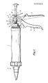
- the dispenser shown in the drawings, and particularly in Figure 1, comprises a barrel 1 to contain the material to be dispensed and having at one end a nozzle assembly 2 and at the other end an operating mechanism 3 by means of which a piston rod 4 can be advanced step by step along the axis of the barrel 1.
- the operating mechanism comprises a body portion 5 having a depending stock 6 which can be grasped in the hand and to which is pivoted a trigger-like member 7.
- a stud 11 On the side of the pivot 8 of the trigger member 7 remote from the finger-engaging portion 9 thereof is a stud 11 which engages an apertured plate 12 through the aperture in which the piston rod 4 passes with some slight clearance.
- the upper edge of the plate 12 rests against a shoulder 13 on the body portion 5 and the plate 12 is biased to the right as seen in the drawing by means of a compression spring 14.
- the piston rod also passes through a second apertured plate 15 which engages against a boss 16 on the body 5 and which is biased to the right as seen in the drawing by means of a compression spring 17.
- the plate 12 moves forward with the piston rod to advance the piston in the barrel 1.
- the rod slides through the plate 15 which is tilted slightly about the stud 16 to allow free movement of the rod 4 through the aperture of the plate.
- the spring 14 returns the plate 12 to the position shown in Figure 1, the plate sliding along the rod 4 which is prevented from moving in the reverse direction by the plate 15 resuming the position shown in Figure 1 and gripping the rod 4.
- the return movement of the plate 12 under the action of the spring 14 also returns the trigger member 7 to the position shown.
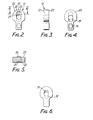
- the gripper 12 is shown in greater detail in Figures 2 to 5 and it will be seen that it consists of a generally key-hole shaped thick plate which is made of sintered metal and in the broad part has a cylindrical hole 21 extending through it from the rear face 22 to the front face 23, the axis of the hole being normal to the two surfaces.
- the rear face 22 is formed with a shallow groove 25 whose width is equal to the diameter of the hole 21 and which has a base which is an arc of a circle.
- the groove extends from a closed end 26 and runs into the hole 21 thus providing an intersection between the groove 25 and the hole 21 which is in the form of a non-circular arc 27.
- the front face 23 is formed with a groove 28 which is of identical form but which runs into the bottom of the hole 21 by comparison with the groove 25 on the rear face which runs into the top of the hole.
- the rod 4 is firmly gripped and considerable force can be applied to the trigger member 7 and hence through the pin 11 and a plate 12 to the rod 4 and hence to the piston in the barrel 1, thus increasing pressure on the co ntents in the barrel and causing it to be expressed through the nozzle 2.
Landscapes
- Engineering & Computer Science (AREA)
- Mechanical Engineering (AREA)
- Coating Apparatus (AREA)
- Mechanical Pencils And Projecting And Retracting Systems Therefor, And Multi-System Writing Instruments (AREA)
- Control Of Motors That Do Not Use Commutators (AREA)
- Control Of Eletrric Generators (AREA)
- Vehicle Body Suspensions (AREA)
- Confectionery (AREA)
Priority Applications (1)
| Application Number | Priority Date | Filing Date | Title |
|---|---|---|---|
| AT87308131T ATE61308T1 (de) | 1986-09-15 | 1987-09-15 | Ausgabevorrichtung. |
Applications Claiming Priority (2)
| Application Number | Priority Date | Filing Date | Title |
|---|---|---|---|
| GB8622178A GB2194989B (en) | 1986-09-15 | 1986-09-15 | Rod advancing mechanisms |
| GB8622178 | 1986-09-15 |
Publications (2)
| Publication Number | Publication Date |
|---|---|
| EP0260925A1 true EP0260925A1 (de) | 1988-03-23 |
| EP0260925B1 EP0260925B1 (de) | 1991-03-06 |
Family
ID=10604208
Family Applications (1)
| Application Number | Title | Priority Date | Filing Date |
|---|---|---|---|
| EP87308131A Expired - Lifetime EP0260925B1 (de) | 1986-09-15 | 1987-09-15 | Ausgabevorrichtung |
Country Status (5)
| Country | Link |
|---|---|
| EP (1) | EP0260925B1 (de) |
| JP (1) | JPS63100969A (de) |
| AT (1) | ATE61308T1 (de) |
| DE (1) | DE3768392D1 (de) |
| GB (1) | GB2194989B (de) |
Cited By (2)
| Publication number | Priority date | Publication date | Assignee | Title |
|---|---|---|---|---|
| US8066714B2 (en) * | 2006-03-17 | 2011-11-29 | Warsaw Orthopedic Inc. | Instrumentation for distraction and insertion of implants in a spinal disc space |
| DE102012216965A1 (de) | 2012-09-21 | 2014-04-17 | Hilti Aktiengesellschaft | Klemmblechoval |
Families Citing this family (7)
| Publication number | Priority date | Publication date | Assignee | Title |
|---|---|---|---|---|
| GB9909498D0 (en) * | 1999-04-23 | 1999-06-23 | Agma Plc | Liquid dispenser |
| AUPQ598100A0 (en) * | 2000-03-01 | 2000-03-23 | Illinois Tool Works Inc. | Cartridge dispensing guns |
| US6874217B2 (en) | 2003-01-09 | 2005-04-05 | Lisle Corporation | Disc brake pad spreading tool |
| US7076850B2 (en) | 2003-01-09 | 2006-07-18 | Lisle Corporation | Dual piston disc brake caliper compressor |
| US8393063B2 (en) | 2011-04-21 | 2013-03-12 | Lisle Corporation | Brake pad spreader tool for disc brake assemblies |
| GB201203829D0 (en) | 2012-03-05 | 2012-04-18 | Buchanan Nigel | Brake calliper tool |
| DE202022102798U1 (de) | 2022-05-20 | 2023-08-24 | Marco Roth | Kartuschenpistole |
Citations (3)
| Publication number | Priority date | Publication date | Assignee | Title |
|---|---|---|---|---|
| GB1264311A (de) * | 1968-02-15 | 1972-02-23 | ||
| US3933273A (en) * | 1973-02-15 | 1976-01-20 | Patrick Clement Cox | Dispenser for expelling contents of collapsible tubes and method of using |
| GB1591495A (en) * | 1977-02-14 | 1981-06-24 | Smithkline Corp | Multiple dose paste dispenser |
Family Cites Families (3)
| Publication number | Priority date | Publication date | Assignee | Title |
|---|---|---|---|---|
| GB1481745A (en) * | 1974-12-11 | 1977-08-03 | Adhesive Tapes Ltd | Hot material applicator |
| GB1555455A (en) * | 1976-06-11 | 1979-11-07 | Cox Mastic Appliances Ltd P C | Dispensing gun |
| AU541325B2 (en) * | 1979-04-10 | 1985-01-03 | Wellcome Foundation Limited, The | Dose dispensing of pastes |
-
1986
- 1986-09-15 GB GB8622178A patent/GB2194989B/en not_active Expired - Lifetime
-
1987
- 1987-09-14 JP JP62228685A patent/JPS63100969A/ja active Pending
- 1987-09-15 AT AT87308131T patent/ATE61308T1/de not_active IP Right Cessation
- 1987-09-15 DE DE8787308131T patent/DE3768392D1/de not_active Expired - Lifetime
- 1987-09-15 EP EP87308131A patent/EP0260925B1/de not_active Expired - Lifetime
Patent Citations (3)
| Publication number | Priority date | Publication date | Assignee | Title |
|---|---|---|---|---|
| GB1264311A (de) * | 1968-02-15 | 1972-02-23 | ||
| US3933273A (en) * | 1973-02-15 | 1976-01-20 | Patrick Clement Cox | Dispenser for expelling contents of collapsible tubes and method of using |
| GB1591495A (en) * | 1977-02-14 | 1981-06-24 | Smithkline Corp | Multiple dose paste dispenser |
Cited By (2)
| Publication number | Priority date | Publication date | Assignee | Title |
|---|---|---|---|---|
| US8066714B2 (en) * | 2006-03-17 | 2011-11-29 | Warsaw Orthopedic Inc. | Instrumentation for distraction and insertion of implants in a spinal disc space |
| DE102012216965A1 (de) | 2012-09-21 | 2014-04-17 | Hilti Aktiengesellschaft | Klemmblechoval |
Also Published As
| Publication number | Publication date |
|---|---|
| ATE61308T1 (de) | 1991-03-15 |
| GB2194989B (en) | 1990-08-08 |
| GB2194989A (en) | 1988-03-23 |
| DE3768392D1 (de) | 1991-04-11 |
| EP0260925B1 (de) | 1991-03-06 |
| JPS63100969A (ja) | 1988-05-06 |
| GB8622178D0 (en) | 1986-10-22 |
Similar Documents
| Publication | Publication Date | Title |
|---|---|---|
| US4072254A (en) | Dispensing guns | |
| CA2038795C (en) | Dispensing gun | |
| EP0260925B1 (de) | Ausgabevorrichtung | |
| US4198756A (en) | Manual extruder | |
| US4566610A (en) | Hand-held device for dispensing a multi-component substance | |
| CN101264597A (zh) | 紧固件枪 | |
| US4273269A (en) | Hand held electric caulking gun | |
| US4264021A (en) | Hand held electric caulking gun | |
| US4840294A (en) | Adjustable dispensing tool | |
| US20080047983A1 (en) | Dispensing apparatus | |
| CA2688361C (en) | Easy shift dual-mode pistol-grip grease gun | |
| KR20080089660A (ko) | 유압 구동식 프레스 장치 및 설비물의 프레스 방법 | |
| EP0566041A1 (de) | Repetierpipette | |
| EP3953541B1 (de) | Absenkmechanismus für handaufbockwerkzeug | |
| EP2433752A2 (de) | Antriebseinheit für eine elektrische Nagelpistole | |
| EP3907011B1 (de) | Klebepistole | |
| US20030074988A1 (en) | Pipette device | |
| CA2203855C (en) | Applicator for dental filling materials | |
| US20040195271A1 (en) | Dispensing apparatus | |
| CN210079978U (zh) | 一种胶枪 | |
| CN102310033B (zh) | 压出设备 | |
| US5511699A (en) | Manually operated tool mechanism | |
| PL80530B1 (de) | ||
| JPH0315808B2 (de) | ||
| EP1063019A2 (de) | Betätigungsgetriebe für eine Schubstange |
Legal Events
| Date | Code | Title | Description |
|---|---|---|---|
| PUAI | Public reference made under article 153(3) epc to a published international application that has entered the european phase |
Free format text: ORIGINAL CODE: 0009012 |
|
| AK | Designated contracting states |
Kind code of ref document: A1 Designated state(s): AT BE CH DE ES FR GB GR IT LI LU NL SE |
|
| 17P | Request for examination filed |
Effective date: 19880915 |
|
| 17Q | First examination report despatched |
Effective date: 19891120 |
|
| RAP1 | Party data changed (applicant data changed or rights of an application transferred) |
Owner name: BBA GROUP PLC. |
|
| GRAA | (expected) grant |
Free format text: ORIGINAL CODE: 0009210 |
|
| AK | Designated contracting states |
Kind code of ref document: B1 Designated state(s): AT BE CH DE ES FR GB GR IT LI LU NL SE |
|
| PG25 | Lapsed in a contracting state [announced via postgrant information from national office to epo] |
Ref country code: IT Free format text: LAPSE BECAUSE OF FAILURE TO SUBMIT A TRANSLATION OF THE DESCRIPTION OR TO PAY THE FEE WITHIN THE PRE;WARNING: LAPSES OF ITALIAN PATENTS WITH EFFECTIVE DATE BEFORE 2007 MAY HAVE OCCURRED AT ANY TIME BEFORE 2007. THE CORRECT EFFECTIVE DATE MAY BE DIFFERENT FROM THE ONE RECORDED.SCRIBED TIME-LIMIT Effective date: 19910306 Ref country code: CH Effective date: 19910306 Ref country code: BE Effective date: 19910306 Ref country code: GR Free format text: LAPSE BECAUSE OF FAILURE TO SUBMIT A TRANSLATION OF THE DESCRIPTION OR TO PAY THE FEE WITHIN THE PRESCRIBED TIME-LIMIT Effective date: 19910306 Ref country code: NL Effective date: 19910306 Ref country code: SE Effective date: 19910306 Ref country code: AT Effective date: 19910306 Ref country code: LI Effective date: 19910306 |
|
| REF | Corresponds to: |
Ref document number: 61308 Country of ref document: AT Date of ref document: 19910315 Kind code of ref document: T |
|
| REF | Corresponds to: |
Ref document number: 3768392 Country of ref document: DE Date of ref document: 19910411 |
|
| ET | Fr: translation filed | ||
| REG | Reference to a national code |
Ref country code: CH Ref legal event code: PL |
|
| PG25 | Lapsed in a contracting state [announced via postgrant information from national office to epo] |
Ref country code: ES Free format text: LAPSE BECAUSE OF FAILURE TO SUBMIT A TRANSLATION OF THE DESCRIPTION OR TO PAY THE FEE WITHIN THE PRESCRIBED TIME-LIMIT Effective date: 19910617 |
|
| NLV1 | Nl: lapsed or annulled due to failure to fulfill the requirements of art. 29p and 29m of the patents act | ||
| PG25 | Lapsed in a contracting state [announced via postgrant information from national office to epo] |
Ref country code: GB Effective date: 19910915 |
|
| PG25 | Lapsed in a contracting state [announced via postgrant information from national office to epo] |
Ref country code: LU Free format text: LAPSE BECAUSE OF NON-PAYMENT OF DUE FEES Effective date: 19910930 |
|
| PLBE | No opposition filed within time limit |
Free format text: ORIGINAL CODE: 0009261 |
|
| STAA | Information on the status of an ep patent application or granted ep patent |
Free format text: STATUS: NO OPPOSITION FILED WITHIN TIME LIMIT |
|
| 26N | No opposition filed | ||
| GBPC | Gb: european patent ceased through non-payment of renewal fee | ||
| REG | Reference to a national code |
Ref country code: FR Ref legal event code: TP |
|
| REG | Reference to a national code |
Ref country code: FR Ref legal event code: CA |
|
| PGFP | Annual fee paid to national office [announced via postgrant information from national office to epo] |
Ref country code: DE Payment date: 20060907 Year of fee payment: 20 |
|
| PGFP | Annual fee paid to national office [announced via postgrant information from national office to epo] |
Ref country code: FR Payment date: 20060908 Year of fee payment: 20 |