EP0260933A2 - Faseroptisches Verschiebungsmessgerät - Google Patents
Faseroptisches Verschiebungsmessgerät Download PDFInfo
- Publication number
- EP0260933A2 EP0260933A2 EP87308149A EP87308149A EP0260933A2 EP 0260933 A2 EP0260933 A2 EP 0260933A2 EP 87308149 A EP87308149 A EP 87308149A EP 87308149 A EP87308149 A EP 87308149A EP 0260933 A2 EP0260933 A2 EP 0260933A2
- Authority
- EP
- European Patent Office
- Prior art keywords
- light
- light source
- face
- fibers
- conduit
- Prior art date
- Legal status (The legal status is an assumption and is not a legal conclusion. Google has not performed a legal analysis and makes no representation as to the accuracy of the status listed.)
- Granted
Links
Images

Classifications
-
- G—PHYSICS
- G01—MEASURING; TESTING
- G01B—MEASURING LENGTH, THICKNESS OR SIMILAR LINEAR DIMENSIONS; MEASURING ANGLES; MEASURING AREAS; MEASURING IRREGULARITIES OF SURFACES OR CONTOURS
- G01B11/00—Measuring arrangements characterised by the use of optical techniques
- G01B11/02—Measuring arrangements characterised by the use of optical techniques for measuring length, width or thickness
-
- G—PHYSICS
- G02—OPTICS
- G02B—OPTICAL ELEMENTS, SYSTEMS OR APPARATUS
- G02B6/00—Light guides; Structural details of arrangements comprising light guides and other optical elements, e.g. couplings
- G02B6/24—Coupling light guides
- G02B6/26—Optical coupling means
- G02B6/32—Optical coupling means having lens focusing means positioned between opposed fibre ends
-
- G—PHYSICS
- G01—MEASURING; TESTING
- G01B—MEASURING LENGTH, THICKNESS OR SIMILAR LINEAR DIMENSIONS; MEASURING ANGLES; MEASURING AREAS; MEASURING IRREGULARITIES OF SURFACES OR CONTOURS
- G01B11/00—Measuring arrangements characterised by the use of optical techniques
-
- G—PHYSICS
- G01—MEASURING; TESTING
- G01D—MEASURING NOT SPECIALLY ADAPTED FOR A SPECIFIC VARIABLE; ARRANGEMENTS FOR MEASURING TWO OR MORE VARIABLES NOT COVERED IN A SINGLE OTHER SUBCLASS; TARIFF METERING APPARATUS; MEASURING OR TESTING NOT OTHERWISE PROVIDED FOR
- G01D5/00—Mechanical means for transferring the output of a sensing member; Means for converting the output of a sensing member to another variable where the form or nature of the sensing member does not constrain the means for converting; Transducers not specially adapted for a specific variable
- G01D5/26—Mechanical means for transferring the output of a sensing member; Means for converting the output of a sensing member to another variable where the form or nature of the sensing member does not constrain the means for converting; Transducers not specially adapted for a specific variable characterised by optical transfer means, i.e. using infrared, visible, or ultraviolet light
- G01D5/268—Mechanical means for transferring the output of a sensing member; Means for converting the output of a sensing member to another variable where the form or nature of the sensing member does not constrain the means for converting; Transducers not specially adapted for a specific variable characterised by optical transfer means, i.e. using infrared, visible, or ultraviolet light using optical fibres
Definitions
- This invention relates to displacement measuring apparatus and, more particularly, to a new and improved fiber optic displacement measuring apparatus having greatly increased working distance and measuring range capabilities.
- Fiber optic displacement measuring devices utilizing a bifurcated fiber optic bundle in combination with a light source and a photo detector or other suitable light receiver for measuring displacements are known.
- One such device is described in Kissinger U.S. Patent No. 3,327,584, and comprises a fiber optic bundle divided at one end into separate arms.
- One arm contains transmitting fibers and the other arm contains receiving fibers.
- the other or common end comprises a common bundle of transmitting and receiving fibers.
- the amount of reflected light is related to the distance between the end face of the fibers in the common bundle and the surface of the target, the diameter of the fibers, the numerical aperture of the fibers, the geometrical distribution of the transmit and received fibers, the total number of fibers, and the reflectivity of the target surface.
- the amount of reflected light peaks and then decreases, however, once the bundle end face and target are separated by a distance on the order of 127 ⁇ m.
- the apparatus described in Kissinger et al. U.S. Patent No. 3,940,608 includes a sensing head having a pair of projection lens mounted so that the end face of the common bundle is adjacent one end of the lens, the other end of the lens adapted to be positioned adjacent the object whose displacement is to be determined.
- the lens is operative, at a predetermined distance from the target, to focus the image of the end face of the common bundle onto the object and to refocus this image back on to the end face so that light transmitted from the fibers associated with the light source is returned upon itself.
- the benefit provided by the '608 patent resides in an increase in the working distance (the distance from the sensing head to the surface to be measured) by a factor of about 100, i.e., from hundredths of a millimeters to millimeters. Moreover, the '608 patent recognizes that by adjusting the gap between the end of the fiber and the lens the working distance may be effectively changed. However, despite the change in working distance, for a given lens configuration, the sensitivity and dynamic range of the structure shown in the '608 patent remains essentially constant.
- the apparatus illustrated in the '608 patent is a highly sensitive measuring device which can restrict its utility in measuring displacement relative to a surface subject to contamination that may affect the reflective characteristics of the target surface. For example, if a panel is being measured with the highly sensitive device of the '608 patent, a relatively small piece of dirt may cause a false reading due to the relatively small focused spot of light striking the target surface.
- the present invention is an improvement over the displacement measuring apparatus of the '608 patent in that it enables displacement determination at greatly increased working distances from a target and over substantially larger dynamic ranges.
- the sensitivity of the displacement measuring apparatus of the invention can be adjusted thereby limiting the likelihood of false readings due to contamination of a target surface in those situations where such contamination is a possibility.
- the sensing head in the '608 patent employs back-to-back projection lenses which constitute a lens that is relatively insensitive to the position of the fiber relative to the lens and provides a focused light spot of essentially the same size for all probe positions (for a given lens).
- the back-to-back lenses of Kissinger et al. are replaced by a single focusing lens which is capable of focusing the end of the fiber conduit at infinity, and means are provided to mount the fiber with respect to the lens so that the position of the fiber relative to the lens can be varied.
- Using a single focusing lens rather than the back-to-back lenses of the '608 patent also enables the user to tailor the general shape of the response curve to a particular application merely by adjusting the distance between the end of the fiber and the lens.
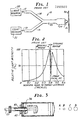
- Figure 1 illustrates the measuring apparatus with which the invention is intended to be used.
- the apparatus is illustrated in Kissinger '608 and includes a glass fiber optic conduit 10 of generally Y configuration.
- the end face 12 of one arm 14 of fiber optic conduit 10 is positioned adjacent a suitable light source 10 and the end face 18 of the other arm 16 is positioned adjacent a photo sensor or other suitable light receiver 22 for receiving light transmitted from light source 10.
- Conduit arms 14 and 16 form a common bundle 23 of optically conducting fibers in the base of the Y which is mounted to an end of a sensing head 24, the other or working end 26 of which is adapted to be positioned adjacent the surface of an object 30 whose displacement or position is to be determined.
- the present invention uses a single lens rather than the pair of microscope lenses as shown in Kissinger '608.
- the lens has the capability of being focused at infinity and should have low aberration and wide aperture.
- focusing refers to positioning of the focused image of the forward face of conduct 23. For example, if the image focal point appears at about 1 cm. (see Figure 2), this means that a sharply focused image of the forward face of conduit 23 appears at that distance from the forward face of the sensing head.
- any of a variety of commercially available lenses may be used in accordance with the invention.
- a microscope lens with a numerical aperture of 0.25 and focal length of 16 mm was used.
- the difference with respect to the Kissinger lens is that, in accordance with the invention, changes in the position of the fiber relative to the lens results in large changes in the focal length and the size of the focused spot of light at the image focal point whereas comparable changes in the fiber position relative to the back-to-back lens arrangement of Kissinger will result in little or no changes in focal length and the size of the focused spot of light at the image focal point.
- FIG 3 shows diagrammatically the structure of a sensing head in accordance with the invention.
- the fiber optic conduit 23 (Figure 1) terminates in a forward face 32.
- the lens shown diagrammatically at 34 is held within a conventional housing 36 which includes a threaded bore 38.
- lens 34 may be one of the projection lenses shown in Kissinger.
- the fiber 23 is retained within a complementary threaded sleeve 40 which can be screwed into the bore 38 and retained by a locking unit 42.
- the position of the terminating face 32 of fiber conduit 23 relative to lens 34 can be finely adjusted. Typically, movement of the fiber 23 over a range of 6.35 mm will enable the image focal point to vary from 0 to infinity.
- Figure 3 also shows the effect of adjusting the position of the fiber optic relative to the lens.
- Four separate positions A through D are shown with position A being the furthest and position D the closest position of the fiber relative to the lens.
- the position of the image focal point changes as shown on the right-hand side of the drawing, with the size of the focused image (or light spot) changing accordingly.
- the change in size of the focused spot indicates a substantial change in sensitivity between positions A and D.
- the ability to vary sensitivity can be an important consideration for a fiber optic measuring device in industrial applications.
- a further important benefit of the invention lies in its capacity to focus at infinity. As explained below, not only does this greatly extend the dynamic range of the device but, in addition, it avoids redundancies inherent in any device where there is a maximum in the response curve at each side of the image focal point. For example, as shown in Figure 2, if distances between 7.62 and 12.7 mm were being measured, a reflective light intensity of 50% would be detected four times corresponding to four different positions of the sensing head with respect to the target. Multiple sensors or complex signal processing apparatus are required in such cases to determine which of the four possible positions was actually located. If, however, in accordance with the invention the lens is focused at infinity, the responsive curve shown in Figure 5 results wherein there is no minimum and, consequently, no redundancies in response. With the lens according to the invention focused at infinity, as shown in Figure 5, the dynamic range is extended to about 13 cm.
- measurements may depend on the location of the null (e.g., to determine whether a part falls within prescribed tolerances) or the shape of the response curve (e.g., for analog-type measurements).
Landscapes
- Physics & Mathematics (AREA)
- General Physics & Mathematics (AREA)
- Optics & Photonics (AREA)
- Length Measuring Devices By Optical Means (AREA)
- Measurement Of Optical Distance (AREA)
Applications Claiming Priority (2)
| Application Number | Priority Date | Filing Date | Title |
|---|---|---|---|
| US90772686A | 1986-09-15 | 1986-09-15 | |
| US907726 | 1986-09-15 |
Publications (3)
| Publication Number | Publication Date |
|---|---|
| EP0260933A2 true EP0260933A2 (de) | 1988-03-23 |
| EP0260933A3 EP0260933A3 (en) | 1989-07-26 |
| EP0260933B1 EP0260933B1 (de) | 1993-02-24 |
Family
ID=25424547
Family Applications (1)
| Application Number | Title | Priority Date | Filing Date |
|---|---|---|---|
| EP87308149A Expired - Lifetime EP0260933B1 (de) | 1986-09-15 | 1987-09-15 | Faseroptisches Verschiebungsmessgerät |
Country Status (4)
| Country | Link |
|---|---|
| EP (1) | EP0260933B1 (de) |
| JP (1) | JPH0786407B2 (de) |
| KR (1) | KR880004301A (de) |
| DE (1) | DE3784291T2 (de) |
Cited By (1)
| Publication number | Priority date | Publication date | Assignee | Title |
|---|---|---|---|---|
| GB2278193A (en) * | 1993-05-19 | 1994-11-23 | Hughes Aircraft Co | Optical measurement of thickness |
Families Citing this family (28)
| Publication number | Priority date | Publication date | Assignee | Title |
|---|---|---|---|---|
| JP2531046B2 (ja) * | 1991-08-31 | 1996-09-04 | 株式会社ニレコ | 光学式ラインマ―ク検出器 |
| US6898773B1 (en) | 2002-01-22 | 2005-05-24 | Cadence Design Systems, Inc. | Method and apparatus for producing multi-layer topological routes |
| US7096448B2 (en) | 2001-01-19 | 2006-08-22 | Cadence Design Systems, Inc. | Method and apparatus for diagonal routing by using several sets of lines |
| US6957408B1 (en) | 2002-01-22 | 2005-10-18 | Cadence Design Systems, Inc. | Method and apparatus for routing nets in an integrated circuit layout |
| US7069530B1 (en) | 2001-06-03 | 2006-06-27 | Cadence Design Systems, Inc. | Method and apparatus for routing groups of paths |
| US6877146B1 (en) | 2001-06-03 | 2005-04-05 | Cadence Design Systems, Inc. | Method and apparatus for routing a set of nets |
| US7107564B1 (en) | 2001-06-03 | 2006-09-12 | Cadence Design Systems, Inc. | Method and apparatus for routing a set of nets |
| US6957411B1 (en) | 2001-06-03 | 2005-10-18 | Cadence Design Systems, Inc. | Gridless IC layout and method and apparatus for generating such a layout |
| US6931616B2 (en) | 2001-08-23 | 2005-08-16 | Cadence Design Systems, Inc. | Routing method and apparatus |
| US7036105B1 (en) | 2002-01-22 | 2006-04-25 | Cadence Design Systems, Inc. | Integrated circuits with at least one layer that has more than one preferred interconnect direction, and method for manufacturing such IC's |
| US7096449B1 (en) | 2002-01-22 | 2006-08-22 | Cadence Design Systems, Inc. | Layouts with routes with different widths in different directions on the same layer, and method and apparatus for generating such layouts |
| US7117468B1 (en) | 2002-01-22 | 2006-10-03 | Cadence Design Systems, Inc. | Layouts with routes with different spacings in different directions on the same layer, and method and apparatus for generating such layouts |
| US7089524B1 (en) | 2002-01-22 | 2006-08-08 | Cadence Design Systems, Inc. | Topological vias route wherein the topological via does not have a coordinate within the region |
| US6938234B1 (en) | 2002-01-22 | 2005-08-30 | Cadence Design Systems, Inc. | Method and apparatus for defining vias |
| US7013451B1 (en) | 2002-01-22 | 2006-03-14 | Cadence Design Systems, Inc. | Method and apparatus for performing routability checking |
| US7080329B1 (en) | 2002-01-22 | 2006-07-18 | Cadence Design Systems, Inc. | Method and apparatus for identifying optimized via locations |
| KR100461197B1 (ko) * | 2002-03-12 | 2004-12-13 | (주)세기엔지니어링 | 광섬유 변위 측정 센서 및 이를 이용한 변위 측정 장치 |
| US6996789B2 (en) | 2002-11-18 | 2006-02-07 | Cadence Design Systems, Inc. | Method and apparatus for performing an exponential path search |
| US7480885B2 (en) | 2002-11-18 | 2009-01-20 | Cadence Design Systems, Inc. | Method and apparatus for routing with independent goals on different layers |
| US6892369B2 (en) | 2002-11-18 | 2005-05-10 | Cadence Design Systems, Inc. | Method and apparatus for costing routes of nets |
| US7080342B2 (en) | 2002-11-18 | 2006-07-18 | Cadence Design Systems, Inc | Method and apparatus for computing capacity of a region for non-Manhattan routing |
| US6988257B2 (en) | 2002-11-18 | 2006-01-17 | Cadence Design Systems, Inc. | Method and apparatus for routing |
| US7010771B2 (en) | 2002-11-18 | 2006-03-07 | Cadence Design Systems, Inc. | Method and apparatus for searching for a global path |
| US7093221B2 (en) | 2002-11-18 | 2006-08-15 | Cadence Design Systems, Inc. | Method and apparatus for identifying a group of routes for a set of nets |
| US7216308B2 (en) | 2002-11-18 | 2007-05-08 | Cadence Design Systems, Inc. | Method and apparatus for solving an optimization problem in an integrated circuit layout |
| US7506295B1 (en) | 2002-12-31 | 2009-03-17 | Cadence Design Systems, Inc. | Non manhattan floor plan architecture for integrated circuits |
| US7089519B1 (en) | 2002-12-31 | 2006-08-08 | Cadence Design System, Inc. | Method and system for performing placement on non Manhattan semiconductor integrated circuits |
| DE102005023992A1 (de) * | 2005-05-20 | 2006-11-23 | TRüTZSCHLER GMBH & CO. KG | Vorrichtung an einer Spinnereivorbereitungsmaschine, z.B. Karde, Krempel, Strecke, Kämmmaschine o.dgl., zum Ermitteln der Masse und/oder Masseschwankungen eines Fasermaterials, z.B. mindestens ein Faserband, Faservlies o.dgl., aus Baumwolle, Chemiefasern o. dgl. |
Family Cites Families (4)
| Publication number | Priority date | Publication date | Assignee | Title |
|---|---|---|---|---|
| US3327584A (en) * | 1963-09-09 | 1967-06-27 | Mechanical Tech Inc | Fiber optic proximity probe |
| US3497701A (en) * | 1967-07-14 | 1970-02-24 | Ibm | Light pen optical system for display apparatus |
| US3788741A (en) * | 1972-07-26 | 1974-01-29 | Syst Res Labor Inc | Distance indicating optical probe |
| US3940608A (en) * | 1974-02-04 | 1976-02-24 | Mechanical Technology Incorporated | Fiber optic displacement measuring apparatus |
-
1987
- 1987-09-15 EP EP87308149A patent/EP0260933B1/de not_active Expired - Lifetime
- 1987-09-15 KR KR870010189A patent/KR880004301A/ko not_active Ceased
- 1987-09-15 DE DE8787308149T patent/DE3784291T2/de not_active Expired - Fee Related
- 1987-09-16 JP JP62231997A patent/JPH0786407B2/ja not_active Expired - Fee Related
Cited By (2)
| Publication number | Priority date | Publication date | Assignee | Title |
|---|---|---|---|---|
| GB2278193A (en) * | 1993-05-19 | 1994-11-23 | Hughes Aircraft Co | Optical measurement of thickness |
| GB2278193B (en) * | 1993-05-19 | 1996-11-06 | Hughes Aircraft Co | Non-contact measurement apparatus |
Also Published As
| Publication number | Publication date |
|---|---|
| DE3784291T2 (de) | 1993-07-22 |
| KR880004301A (ko) | 1988-06-03 |
| EP0260933A3 (en) | 1989-07-26 |
| JPH0786407B2 (ja) | 1995-09-20 |
| EP0260933B1 (de) | 1993-02-24 |
| DE3784291D1 (de) | 1993-04-01 |
| JPS63120201A (ja) | 1988-05-24 |
Similar Documents
| Publication | Publication Date | Title |
|---|---|---|
| EP0260933B1 (de) | Faseroptisches Verschiebungsmessgerät | |
| AU595937B2 (en) | Laser probe for determining distance | |
| US4764016A (en) | Instrument for measuring the topography of a surface | |
| KR100660952B1 (ko) | 레이저 스캐너 측정 시스템 | |
| EP0279347B1 (de) | Optische Achsenverschiebungsfühler | |
| US5483347A (en) | Non-contact measurement apparatus using bifurcated optical fiber bundle with intermixed fibers | |
| JP2621430B2 (ja) | 光センサー | |
| JPH06509415A (ja) | 探触子 | |
| CN111721235B (zh) | 一种光电式边缘检测系统及其检测方法 | |
| US4672200A (en) | Optical inspection of transparent layers | |
| GB2160310A (en) | Optical displacement sensor | |
| US5073027A (en) | Fiber optic displacement measuring apparatus | |
| JPS61132809A (ja) | 撓み又は捩れ測定用センサー | |
| US4701611A (en) | Reflectivity compensated fiber optic sensor | |
| US4946275A (en) | Fiber optic position transducer | |
| US4600836A (en) | Diaphragm deflection sensor for fused silica diaphragm module | |
| EP0157606B1 (de) | Hochtemperaturdruckwandler und Systeme zur Bestimmung der Durchbiegung von Druckwandlermembranen | |
| EP0130337A2 (de) | Optische Messvorrichtung | |
| US7880902B2 (en) | Contactless optical probe and device and method making use thereof | |
| JP4182211B2 (ja) | 光導波路を用いた光反射式計測装置 | |
| Ikawa et al. | Photoelectronic displacement sensor with nanometre resolution | |
| EP0427692A3 (de) | Berührungsloser Messtaster | |
| JPS63263412A (ja) | 非接触変位計 | |
| CA1150049A (en) | Electro-optical distance-measuring system | |
| Domanski et al. | Optimal distribution of optical fibers in surface roughness sensor |
Legal Events
| Date | Code | Title | Description |
|---|---|---|---|
| PUAI | Public reference made under article 153(3) epc to a published international application that has entered the european phase |
Free format text: ORIGINAL CODE: 0009012 |
|
| AK | Designated contracting states |
Kind code of ref document: A2 Designated state(s): DE FR GB IT |
|
| PUAL | Search report despatched |
Free format text: ORIGINAL CODE: 0009013 |
|
| AK | Designated contracting states |
Kind code of ref document: A3 Designated state(s): DE FR GB IT |
|
| 17P | Request for examination filed |
Effective date: 19900119 |
|
| 17Q | First examination report despatched |
Effective date: 19901220 |
|
| GRAA | (expected) grant |
Free format text: ORIGINAL CODE: 0009210 |
|
| AK | Designated contracting states |
Kind code of ref document: B1 Designated state(s): DE FR GB IT |
|
| REF | Corresponds to: |
Ref document number: 3784291 Country of ref document: DE Date of ref document: 19930401 |
|
| ET | Fr: translation filed | ||
| ITF | It: translation for a ep patent filed | ||
| PLBE | No opposition filed within time limit |
Free format text: ORIGINAL CODE: 0009261 |
|
| STAA | Information on the status of an ep patent application or granted ep patent |
Free format text: STATUS: NO OPPOSITION FILED WITHIN TIME LIMIT |
|
| ITPR | It: changes in ownership of a european patent |
Owner name: CAMBIO RAGIONE SOCIALE;3M FIBER OPTIC AND MANUFACT |
|
| 26N | No opposition filed | ||
| REG | Reference to a national code |
Ref country code: GB Ref legal event code: IF02 |
|
| PGFP | Annual fee paid to national office [announced via postgrant information from national office to epo] |
Ref country code: GB Payment date: 20030910 Year of fee payment: 17 |
|
| PGFP | Annual fee paid to national office [announced via postgrant information from national office to epo] |
Ref country code: FR Payment date: 20030918 Year of fee payment: 17 |
|
| PGFP | Annual fee paid to national office [announced via postgrant information from national office to epo] |
Ref country code: DE Payment date: 20031031 Year of fee payment: 17 |
|
| PG25 | Lapsed in a contracting state [announced via postgrant information from national office to epo] |
Ref country code: GB Free format text: LAPSE BECAUSE OF NON-PAYMENT OF DUE FEES Effective date: 20040915 |
|
| PG25 | Lapsed in a contracting state [announced via postgrant information from national office to epo] |
Ref country code: DE Free format text: LAPSE BECAUSE OF NON-PAYMENT OF DUE FEES Effective date: 20050401 |
|
| GBPC | Gb: european patent ceased through non-payment of renewal fee |
Effective date: 20040915 |
|
| PG25 | Lapsed in a contracting state [announced via postgrant information from national office to epo] |
Ref country code: FR Free format text: LAPSE BECAUSE OF NON-PAYMENT OF DUE FEES Effective date: 20050531 |
|
| REG | Reference to a national code |
Ref country code: FR Ref legal event code: ST |
|
| PG25 | Lapsed in a contracting state [announced via postgrant information from national office to epo] |
Ref country code: IT Free format text: LAPSE BECAUSE OF NON-PAYMENT OF DUE FEES;WARNING: LAPSES OF ITALIAN PATENTS WITH EFFECTIVE DATE BEFORE 2007 MAY HAVE OCCURRED AT ANY TIME BEFORE 2007. THE CORRECT EFFECTIVE DATE MAY BE DIFFERENT FROM THE ONE RECORDED. Effective date: 20050915 |