EP0260967B1 - Steckverbinder mit verformbarem Haltebügel - Google Patents
Steckverbinder mit verformbarem Haltebügel Download PDFInfo
- Publication number
- EP0260967B1 EP0260967B1 EP87308230A EP87308230A EP0260967B1 EP 0260967 B1 EP0260967 B1 EP 0260967B1 EP 87308230 A EP87308230 A EP 87308230A EP 87308230 A EP87308230 A EP 87308230A EP 0260967 B1 EP0260967 B1 EP 0260967B1
- Authority
- EP
- European Patent Office
- Prior art keywords
- post
- ribs
- housing
- locating
- connector
- Prior art date
- Legal status (The legal status is an assumption and is not a legal conclusion. Google has not performed a legal analysis and makes no representation as to the accuracy of the status listed.)
- Expired - Lifetime
Links
Images
Classifications
-
- H—ELECTRICITY
- H05—ELECTRIC TECHNIQUES NOT OTHERWISE PROVIDED FOR
- H05K—PRINTED CIRCUITS; CASINGS OR CONSTRUCTIONAL DETAILS OF ELECTRIC APPARATUS; MANUFACTURE OF ASSEMBLAGES OF ELECTRICAL COMPONENTS
- H05K5/00—Casings, cabinets or drawers for electric apparatus
-
- H—ELECTRICITY
- H05—ELECTRIC TECHNIQUES NOT OTHERWISE PROVIDED FOR
- H05K—PRINTED CIRCUITS; CASINGS OR CONSTRUCTIONAL DETAILS OF ELECTRIC APPARATUS; MANUFACTURE OF ASSEMBLAGES OF ELECTRICAL COMPONENTS
- H05K3/00—Apparatus or processes for manufacturing printed circuits
- H05K3/30—Assembling printed circuits with electric components, e.g. with resistors
- H05K3/303—Assembling printed circuits with electric components, e.g. with resistors with surface mounted components
-
- H—ELECTRICITY
- H01—ELECTRIC ELEMENTS
- H01R—ELECTRICALLY-CONDUCTIVE CONNECTIONS; STRUCTURAL ASSOCIATIONS OF A PLURALITY OF MUTUALLY-INSULATED ELECTRICAL CONNECTING ELEMENTS; COUPLING DEVICES; CURRENT COLLECTORS
- H01R12/00—Structural associations of a plurality of mutually-insulated electrical connecting elements, specially adapted for printed circuits, e.g. printed circuit boards [PCB], flat or ribbon cables, or like generally planar structures, e.g. terminal strips, terminal blocks; Coupling devices specially adapted for printed circuits, flat or ribbon cables, or like generally planar structures; Terminals specially adapted for contact with, or insertion into, printed circuits, flat or ribbon cables, or like generally planar structures
- H01R12/70—Coupling devices
- H01R12/7005—Guiding, mounting, polarizing or locking means; Extractors
- H01R12/7011—Locking or fixing a connector to a PCB
- H01R12/7017—Snap means
- H01R12/7029—Snap means not integral with the coupling device
-
- H—ELECTRICITY
- H05—ELECTRIC TECHNIQUES NOT OTHERWISE PROVIDED FOR
- H05K—PRINTED CIRCUITS; CASINGS OR CONSTRUCTIONAL DETAILS OF ELECTRIC APPARATUS; MANUFACTURE OF ASSEMBLAGES OF ELECTRICAL COMPONENTS
- H05K1/00—Printed circuits
-
- H—ELECTRICITY
- H01—ELECTRIC ELEMENTS
- H01R—ELECTRICALLY-CONDUCTIVE CONNECTIONS; STRUCTURAL ASSOCIATIONS OF A PLURALITY OF MUTUALLY-INSULATED ELECTRICAL CONNECTING ELEMENTS; COUPLING DEVICES; CURRENT COLLECTORS
- H01R43/00—Apparatus or processes specially adapted for manufacturing, assembling, maintaining, or repairing of line connectors or current collectors or for joining electric conductors
- H01R43/02—Apparatus or processes specially adapted for manufacturing, assembling, maintaining, or repairing of line connectors or current collectors or for joining electric conductors for soldered or welded connections
-
- H—ELECTRICITY
- H05—ELECTRIC TECHNIQUES NOT OTHERWISE PROVIDED FOR
- H05K—PRINTED CIRCUITS; CASINGS OR CONSTRUCTIONAL DETAILS OF ELECTRIC APPARATUS; MANUFACTURE OF ASSEMBLAGES OF ELECTRICAL COMPONENTS
- H05K2201/00—Indexing scheme relating to printed circuits covered by H05K1/00
- H05K2201/10—Details of components or other objects attached to or integrated in a printed circuit board
- H05K2201/10007—Types of components
- H05K2201/10189—Non-printed connector
-
- H—ELECTRICITY
- H05—ELECTRIC TECHNIQUES NOT OTHERWISE PROVIDED FOR
- H05K—PRINTED CIRCUITS; CASINGS OR CONSTRUCTIONAL DETAILS OF ELECTRIC APPARATUS; MANUFACTURE OF ASSEMBLAGES OF ELECTRICAL COMPONENTS
- H05K2201/00—Indexing scheme relating to printed circuits covered by H05K1/00
- H05K2201/10—Details of components or other objects attached to or integrated in a printed circuit board
- H05K2201/10431—Details of mounted components
- H05K2201/10568—Integral adaptations of a component or an auxiliary PCB for mounting, e.g. integral spacer element
-
- H—ELECTRICITY
- H05—ELECTRIC TECHNIQUES NOT OTHERWISE PROVIDED FOR
- H05K—PRINTED CIRCUITS; CASINGS OR CONSTRUCTIONAL DETAILS OF ELECTRIC APPARATUS; MANUFACTURE OF ASSEMBLAGES OF ELECTRICAL COMPONENTS
- H05K2201/00—Indexing scheme relating to printed circuits covered by H05K1/00
- H05K2201/10—Details of components or other objects attached to or integrated in a printed circuit board
- H05K2201/10431—Details of mounted components
- H05K2201/10598—Means for fastening a component, a casing or a heat sink whereby a pressure is exerted on the component towards the PCB
-
- Y—GENERAL TAGGING OF NEW TECHNOLOGICAL DEVELOPMENTS; GENERAL TAGGING OF CROSS-SECTIONAL TECHNOLOGIES SPANNING OVER SEVERAL SECTIONS OF THE IPC; TECHNICAL SUBJECTS COVERED BY FORMER USPC CROSS-REFERENCE ART COLLECTIONS [XRACs] AND DIGESTS
- Y02—TECHNOLOGIES OR APPLICATIONS FOR MITIGATION OR ADAPTATION AGAINST CLIMATE CHANGE
- Y02P—CLIMATE CHANGE MITIGATION TECHNOLOGIES IN THE PRODUCTION OR PROCESSING OF GOODS
- Y02P70/00—Climate change mitigation technologies in the production process for final industrial or consumer products
- Y02P70/50—Manufacturing or production processes characterised by the final manufactured product
-
- Y—GENERAL TAGGING OF NEW TECHNOLOGICAL DEVELOPMENTS; GENERAL TAGGING OF CROSS-SECTIONAL TECHNOLOGIES SPANNING OVER SEVERAL SECTIONS OF THE IPC; TECHNICAL SUBJECTS COVERED BY FORMER USPC CROSS-REFERENCE ART COLLECTIONS [XRACs] AND DIGESTS
- Y10—TECHNICAL SUBJECTS COVERED BY FORMER USPC
- Y10S—TECHNICAL SUBJECTS COVERED BY FORMER USPC CROSS-REFERENCE ART COLLECTIONS [XRACs] AND DIGESTS
- Y10S411/00—Expanded, threaded, driven, headed, tool-deformed, or locked-threaded fastener
- Y10S411/904—Fastener or fastener element composed of nonmetallic material
- Y10S411/908—Resinous material
-
- Y—GENERAL TAGGING OF NEW TECHNOLOGICAL DEVELOPMENTS; GENERAL TAGGING OF CROSS-SECTIONAL TECHNOLOGIES SPANNING OVER SEVERAL SECTIONS OF THE IPC; TECHNICAL SUBJECTS COVERED BY FORMER USPC CROSS-REFERENCE ART COLLECTIONS [XRACs] AND DIGESTS
- Y10—TECHNICAL SUBJECTS COVERED BY FORMER USPC
- Y10T—TECHNICAL SUBJECTS COVERED BY FORMER US CLASSIFICATION
- Y10T24/00—Buckles, buttons, clasps, etc.
- Y10T24/42—Independent, headed, aperture pass-through fastener
Definitions
- This invention relates to connectors for printed wiring boards and more particularly it relates to means for locating and holding the connector to the wiring board until soldered.
- the mechanics of holding a card connector housing to a printed wiring board (PWB) until it is soldered involves either mechanical fasteners (screws, rivets, etc.), weighted plates placed on top of components and removed after soldering, or posts integral with the housing. Molded posts which are part of the housing are particularly suited for surface mount connectors. Such connectors are known from e.g. US-A-4435031.
- the posts provide a means for accurately locating the connector legs to the PWB solder pad and holding the connector in place during the soldering process by engaging holes located in the PWB. There is an interference fit between the posts and the holes. With known post designs of various shapes the interference fit results in material being scraped from the post as it is inserted into the locating hole. These scrapings present assembly problems by preventing contact between the connector and PWB.
- means for locating and holding a connector housing to a printed wiring board having locating holes therein comprising: a post extending from said housing for engaging said holes with an interference fit to locate the housing with respect to said printed wiring board characterised by said post having a plurality of ribs extending outwardly from the post at locations around the post and an elongated longitudinal bore, the transversal crossection of which having a major axis aligned with diagonally opposed junctures of adjoining ribs and sized to provide a frangible juncture which separates when said post is inserted in a locating hole.
- the post forms two separated legs from the integral post allowing the ribs to flex to conform easily to the hole size or location without scraping material from the post and to reduce insertion forces.
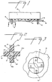
- the embodiment chosen for purposes of illustration includes a connector housing 10 having terminals 12 and locating posts 14 fastened to and extending downwardly from the housing.
- the posts 14 are shown inserted through locating holes 16 of PWB 18.
- the posts 14 are sized for an interference fit with holes 16 and are preferably molded as an integral part of the housing 10.
- each post 14 is seen to have a plurality of ribs numbered 15, 15 a , 15 b and 15 c located around the post at an angle 17 of about ninety degrees to each other.
- the bore 20 is shown with a crossection in the shape of an oval with its major axis 21 aligned with directly opposed junctures 22, 24 of adjoining ribs 15, 15 a , 15 b and 15 c .
- the bore is sized to provide frangible walls at junctures 22, 24 which separate when the post 14 is inserted in hole 16 of PWB 18 as best shown in Fig. 3.
- the bore 20 breaks through the junctures of ribs 15, 15 a and 15 b , 15 c allowing the ribs to flex.
- the cross configuration shown provides four narrow surfaces which easily conform to hole size or location without scraping the post or ribs as the case may be.
Landscapes
- Engineering & Computer Science (AREA)
- Microelectronics & Electronic Packaging (AREA)
- Manufacturing & Machinery (AREA)
- Multi-Conductor Connections (AREA)
- Coupling Device And Connection With Printed Circuit (AREA)
Claims (2)
- Einrichtung zum Ausrichten und Halten eines Verbindergehäuses (10) zu/an einer gedruckten Schaltungsplatte (18), die Ausrichtöffnungen (16) darin hat, wobei die Einrichtung aufweist: einen zapfenförmigen Halter (14), der sich von dem Gehäuse (10) wegerstreckt und mittels eines Festsitzes in Eingriff mit den Öffnungen (16) kommt, um das Gehäuse (10) bezüglich der gedruckten Schaltungsplatte (18) auszurichten, dadurch gekennzeichnet, daß der zapfenförmige Halter (14) eine Mehrzahl von Rippen (15, 15a, 15b, 15c) hat, die von dem zapfenförmigen Halter (14) an Stellen um den zapfenförmigen Halter nach außen verlaufen, sowie eine längliche, in Längsrichtung verlaufende Bohrung (20) hat, deren Querschnitt eine Hauptachse (21) hat, die zu den diagonal gegenüberliegenden Verbindungsstellen (22, 24) von benachbarten Rippen (15, 15c und 15a, 15b) ausgerichtet und derart bemessen ist, daß man eine brechbare Verbindung erhält, die sich trennen läßt, wenn der zapfenförmige Halter (14) in eine Ausrichtöffnung (16) eingeführt wird.
- Einrichtung nach Anspruch 1, bei der der zapfenförmige Halter (14) vier Rippen (15, 15a, 15b, 15c) hat, die um 90° zueinander vorgesehen sind, und bei der die längliche, in Längsrichtung verlaufende Bohrung (20) einen Querschnitt besitzt, der eine Hauptachse hat, die zu den diagonal gegenüberliegenden Verbindungsstellen von benachbarten Rippen ausgerichtet ist.
Applications Claiming Priority (2)
| Application Number | Priority Date | Filing Date | Title |
|---|---|---|---|
| US06/910,456 US4691971A (en) | 1986-09-17 | 1986-09-17 | Connector with compliant retainer |
| US910456 | 1986-09-17 |
Publications (2)
| Publication Number | Publication Date |
|---|---|
| EP0260967A1 EP0260967A1 (de) | 1988-03-23 |
| EP0260967B1 true EP0260967B1 (de) | 1991-10-30 |
Family
ID=25428806
Family Applications (1)
| Application Number | Title | Priority Date | Filing Date |
|---|---|---|---|
| EP87308230A Expired - Lifetime EP0260967B1 (de) | 1986-09-17 | 1987-09-17 | Steckverbinder mit verformbarem Haltebügel |
Country Status (7)
| Country | Link |
|---|---|
| US (1) | US4691971A (de) |
| EP (1) | EP0260967B1 (de) |
| JP (1) | JPS6381776A (de) |
| KR (1) | KR900004377B1 (de) |
| AU (1) | AU590967B2 (de) |
| CA (1) | CA1280476C (de) |
| DE (1) | DE3774225D1 (de) |
Cited By (1)
| Publication number | Priority date | Publication date | Assignee | Title |
|---|---|---|---|---|
| DE4218431A1 (de) * | 1992-06-04 | 1993-12-09 | Cannon Electric Gmbh | Einrichtung zur Verbindung eines Steckverbinders mit einer Leiterplatte |
Families Citing this family (17)
| Publication number | Priority date | Publication date | Assignee | Title |
|---|---|---|---|---|
| IL93863A0 (en) * | 1989-03-31 | 1990-12-23 | Du Pont | Connector with means for securing to a substrate |
| US5017151A (en) * | 1990-10-05 | 1991-05-21 | Molex Incorporated | Floating panel mount for electrical connectors |
| US5120256A (en) * | 1991-07-16 | 1992-06-09 | Walden John D | Retention system for a connector housing |
| JP3302689B2 (ja) * | 1991-07-16 | 2002-07-15 | バーグ・テクノロジー・インコーポレーテッド | コネクタハウジングのための保持システム |
| WO1993008619A1 (en) * | 1991-10-15 | 1993-04-29 | Itt Industries, Inc. | Peg-held connector |
| DE9303464U1 (de) * | 1993-03-09 | 1993-04-29 | Siemens AG, 8000 München | Einpreß-Befestigung für Bauteile in Leiterplattenbohrungen |
| US5334047A (en) * | 1993-03-12 | 1994-08-02 | Thomas & Betts Corporation | Electrical connector mounting posts |
| TW303427B (de) * | 1994-06-10 | 1997-04-21 | Sony Co Ltd | |
| DE9414371U1 (de) * | 1994-09-05 | 1995-02-09 | Siemens AG, 80333 München | Wiederverwendbare hochpolige Steckverbindung |
| US5619018A (en) * | 1995-04-03 | 1997-04-08 | Compaq Computer Corporation | Low weight multilayer printed circuit board |
| US5589669A (en) * | 1995-12-28 | 1996-12-31 | Emc Corporation | Electrical contact for printed circuit boards |
| US6179631B1 (en) | 1997-11-21 | 2001-01-30 | Emc Corporation | Electrical contact for a printed circuit board |
| US6155433A (en) * | 1997-12-01 | 2000-12-05 | Intel Corporation | Dual processor retention module |
| US6270374B1 (en) | 1998-01-20 | 2001-08-07 | Berg Technology, Inc. | Electrical connector with wafer for video positioning and surface mount holding feature |
| US6030234A (en) * | 1998-01-23 | 2000-02-29 | Molex Incorporated | Terminal pins mounted in flexible substrates |
| JPH11330766A (ja) * | 1998-05-11 | 1999-11-30 | Alps Electric Co Ltd | 電子機器 |
| US6554643B1 (en) | 1999-05-28 | 2003-04-29 | Fci Technology, Inc. | Connector press fit mounting projection |
Family Cites Families (13)
| Publication number | Priority date | Publication date | Assignee | Title |
|---|---|---|---|---|
| FR1040322A (fr) * | 1951-08-03 | 1953-10-14 | Borne de contact électrique | |
| US2909957A (en) * | 1956-04-26 | 1959-10-27 | Illinois Tool Works | Resilient plastic fastener with strut supported legs |
| GB1066861A (en) * | 1963-02-22 | 1967-04-26 | Carr Fastener Co Ltd | Clip for fastening together two apertured panels |
| DE7529437U (de) * | 1974-09-23 | 1976-10-14 | Thomas & Betts Corp., Elizabeth, N.J. (V.St.A.) | |
| JPS5163460A (en) * | 1974-10-10 | 1976-06-01 | Du Pont | Kairobanpin oyobi hoho |
| US4050772A (en) * | 1975-05-21 | 1977-09-27 | Jean Birnholz | Unitary socket terminal for electronic circuits |
| DE2718170C3 (de) * | 1977-04-23 | 1979-10-25 | Ford-Werke Ag, 5000 Koeln | Befestigungsclip für verkleidete Abdeckplatten, insbesondere für Kraftfahrzeuge |
| US4457570A (en) * | 1980-02-12 | 1984-07-03 | Virginia Patent Development Corporation | Connector for mating modular plug with printed circuit board |
| US4195900A (en) * | 1979-03-22 | 1980-04-01 | Amp Incorporated | Terminal housing having improved mounting means |
| US4435031A (en) * | 1982-01-07 | 1984-03-06 | Holmberg Electronics Corporation | Connector block with snap latch |
| US4533204A (en) * | 1982-08-23 | 1985-08-06 | Minnesota Mining And Manufacturing Company | Resilient circuit board contact |
| CA1167127A (en) * | 1983-01-14 | 1984-05-08 | Otto H.D. Marx | Electrical connector structure and method of manufacture |
| DE3533339A1 (de) * | 1985-09-16 | 1987-03-26 | Siemens Ag | Verfahren zur herstellung von einpresszonen fuer kontaktteile |
-
1986
- 1986-09-17 US US06/910,456 patent/US4691971A/en not_active Expired - Lifetime
-
1987
- 1987-09-14 AU AU78365/87A patent/AU590967B2/en not_active Ceased
- 1987-09-15 CA CA000546931A patent/CA1280476C/en not_active Expired - Lifetime
- 1987-09-16 JP JP62229938A patent/JPS6381776A/ja active Granted
- 1987-09-16 KR KR1019870010242A patent/KR900004377B1/ko not_active Expired
- 1987-09-17 DE DE8787308230T patent/DE3774225D1/de not_active Expired - Lifetime
- 1987-09-17 EP EP87308230A patent/EP0260967B1/de not_active Expired - Lifetime
Cited By (1)
| Publication number | Priority date | Publication date | Assignee | Title |
|---|---|---|---|---|
| DE4218431A1 (de) * | 1992-06-04 | 1993-12-09 | Cannon Electric Gmbh | Einrichtung zur Verbindung eines Steckverbinders mit einer Leiterplatte |
Also Published As
| Publication number | Publication date |
|---|---|
| AU7836587A (en) | 1988-03-24 |
| DE3774225D1 (de) | 1991-12-05 |
| JPS6381776A (ja) | 1988-04-12 |
| KR900004377B1 (ko) | 1990-06-23 |
| KR890006127A (ko) | 1989-05-18 |
| CA1280476C (en) | 1991-02-19 |
| AU590967B2 (en) | 1989-11-23 |
| JPH0378753B2 (de) | 1991-12-16 |
| US4691971A (en) | 1987-09-08 |
| EP0260967A1 (de) | 1988-03-23 |
Similar Documents
| Publication | Publication Date | Title |
|---|---|---|
| EP0260967B1 (de) | Steckverbinder mit verformbarem Haltebügel | |
| EP0825680B1 (de) | Verformbarer elektrischer Verbindungsstift | |
| US4715820A (en) | Connection system for printed circuit boards | |
| US5277596A (en) | Method of producing a card edge mounted connector and the resulting assembly thereof | |
| KR970002791Y1 (ko) | 헤더(header)장치 | |
| US5173063A (en) | Receptacle connector having protected power contacts | |
| EP0633634A2 (de) | System zur Behandlung von elektrischen Verbindern mittels eine Vakuum-Saugdüse | |
| EP0043224A2 (de) | Scheinelement-Maske für gedruckte Schaltungsplatten | |
| ATE52361T1 (de) | Elektrischer kontaktstift fuer gedruckte leiterplatte. | |
| EP0764351B1 (de) | Elektrischer steckverbinder mit selbsthalterungsriegel | |
| US4854882A (en) | Floatable surface mount terminal | |
| EP0443492A1 (de) | Steckverbinder mit geschützten Leistungskontakten | |
| US4685031A (en) | Edgeboard connector | |
| US5884393A (en) | Mounting jig for electrical connectors | |
| EP0646290B1 (de) | Oberflächenmontierbarer verbinder | |
| CA2104438A1 (en) | Method and Apparatus for Mounting Connectors | |
| EP0989631B1 (de) | Veränderungssystem für gedruckte Schaltungsverbindungen nach Installierung | |
| KR100470512B1 (ko) | 커넥터분리로케이터탭 | |
| US6089911A (en) | Apparatus and method for mounting a plurality of surface mount contacts | |
| JPH02943Y2 (de) | ||
| KR0137166Y1 (ko) | 전자기기의 접지장치 | |
| US4604798A (en) | Extractor for spring-lock pin connectors | |
| KR200156865Y1 (ko) | 반도체 패키지 고정장치 | |
| GB2230990A (en) | Hole plug and method of plugging holes | |
| GB2271221A (en) | Mounting an electrical connector on a PCB |
Legal Events
| Date | Code | Title | Description |
|---|---|---|---|
| PUAI | Public reference made under article 153(3) epc to a published international application that has entered the european phase |
Free format text: ORIGINAL CODE: 0009012 |
|
| AK | Designated contracting states |
Kind code of ref document: A1 Designated state(s): BE CH DE FR GB IT LI LU NL SE |
|
| 17P | Request for examination filed |
Effective date: 19880517 |
|
| 17Q | First examination report despatched |
Effective date: 19910228 |
|
| GRAA | (expected) grant |
Free format text: ORIGINAL CODE: 0009210 |
|
| AK | Designated contracting states |
Kind code of ref document: B1 Designated state(s): BE CH DE FR GB IT LI LU NL SE |
|
| ET | Fr: translation filed | ||
| ITF | It: translation for a ep patent filed | ||
| REF | Corresponds to: |
Ref document number: 3774225 Country of ref document: DE Date of ref document: 19911205 |
|
| PGFP | Annual fee paid to national office [announced via postgrant information from national office to epo] |
Ref country code: CH Payment date: 19920828 Year of fee payment: 6 |
|
| PGFP | Annual fee paid to national office [announced via postgrant information from national office to epo] |
Ref country code: LU Payment date: 19920902 Year of fee payment: 6 |
|
| PLBE | No opposition filed within time limit |
Free format text: ORIGINAL CODE: 0009261 |
|
| STAA | Information on the status of an ep patent application or granted ep patent |
Free format text: STATUS: NO OPPOSITION FILED WITHIN TIME LIMIT |
|
| PGFP | Annual fee paid to national office [announced via postgrant information from national office to epo] |
Ref country code: SE Payment date: 19920918 Year of fee payment: 6 |
|
| PGFP | Annual fee paid to national office [announced via postgrant information from national office to epo] |
Ref country code: NL Payment date: 19920930 Year of fee payment: 6 |
|
| PGFP | Annual fee paid to national office [announced via postgrant information from national office to epo] |
Ref country code: BE Payment date: 19921013 Year of fee payment: 6 |
|
| 26N | No opposition filed | ||
| EPTA | Lu: last paid annual fee | ||
| PG25 | Lapsed in a contracting state [announced via postgrant information from national office to epo] |
Ref country code: LU Free format text: LAPSE BECAUSE OF NON-PAYMENT OF DUE FEES Effective date: 19930917 |
|
| PG25 | Lapsed in a contracting state [announced via postgrant information from national office to epo] |
Ref country code: SE Effective date: 19930918 |
|
| PG25 | Lapsed in a contracting state [announced via postgrant information from national office to epo] |
Ref country code: LI Effective date: 19930930 Ref country code: CH Effective date: 19930930 Ref country code: BE Effective date: 19930930 |
|
| BERE | Be: lapsed |
Owner name: E.I. DU PONT DE NEMOURS AND CY Effective date: 19930930 |
|
| PG25 | Lapsed in a contracting state [announced via postgrant information from national office to epo] |
Ref country code: NL Effective date: 19940401 |
|
| NLV4 | Nl: lapsed or anulled due to non-payment of the annual fee | ||
| REG | Reference to a national code |
Ref country code: CH Ref legal event code: PL |
|
| EUG | Se: european patent has lapsed |
Ref document number: 87308230.9 Effective date: 19940410 |
|
| REG | Reference to a national code |
Ref country code: GB Ref legal event code: 732E |
|
| REG | Reference to a national code |
Ref country code: FR Ref legal event code: TP |
|
| PGFP | Annual fee paid to national office [announced via postgrant information from national office to epo] |
Ref country code: GB Payment date: 19980806 Year of fee payment: 12 |
|
| PGFP | Annual fee paid to national office [announced via postgrant information from national office to epo] |
Ref country code: FR Payment date: 19980902 Year of fee payment: 12 |
|
| PGFP | Annual fee paid to national office [announced via postgrant information from national office to epo] |
Ref country code: DE Payment date: 19980928 Year of fee payment: 12 |
|
| PG25 | Lapsed in a contracting state [announced via postgrant information from national office to epo] |
Ref country code: GB Free format text: LAPSE BECAUSE OF NON-PAYMENT OF DUE FEES Effective date: 19990917 |
|
| GBPC | Gb: european patent ceased through non-payment of renewal fee |
Effective date: 19990917 |
|
| PG25 | Lapsed in a contracting state [announced via postgrant information from national office to epo] |
Ref country code: FR Free format text: LAPSE BECAUSE OF NON-PAYMENT OF DUE FEES Effective date: 20000531 |
|
| PG25 | Lapsed in a contracting state [announced via postgrant information from national office to epo] |
Ref country code: DE Free format text: LAPSE BECAUSE OF NON-PAYMENT OF DUE FEES Effective date: 20000701 |
|
| REG | Reference to a national code |
Ref country code: FR Ref legal event code: ST |
|
| PG25 | Lapsed in a contracting state [announced via postgrant information from national office to epo] |
Ref country code: IT Free format text: LAPSE BECAUSE OF NON-PAYMENT OF DUE FEES Effective date: 20050917 |