EP0260973A2 - Grille d'aération ressemblant à une persienne - Google Patents
Grille d'aération ressemblant à une persienne Download PDFInfo
- Publication number
- EP0260973A2 EP0260973A2 EP87308248A EP87308248A EP0260973A2 EP 0260973 A2 EP0260973 A2 EP 0260973A2 EP 87308248 A EP87308248 A EP 87308248A EP 87308248 A EP87308248 A EP 87308248A EP 0260973 A2 EP0260973 A2 EP 0260973A2
- Authority
- EP
- European Patent Office
- Prior art keywords
- louvered
- ventilator
- louver
- normal
- curved
- Prior art date
- Legal status (The legal status is an assumption and is not a legal conclusion. Google has not performed a legal analysis and makes no representation as to the accuracy of the status listed.)
- Withdrawn
Links
Images

Classifications
-
- F—MECHANICAL ENGINEERING; LIGHTING; HEATING; WEAPONS; BLASTING
- F24—HEATING; RANGES; VENTILATING
- F24F—AIR-CONDITIONING; AIR-HUMIDIFICATION; VENTILATION; USE OF AIR CURRENTS FOR SCREENING
- F24F13/00—Details common to, or for air-conditioning, air-humidification, ventilation or use of air currents for screening
- F24F13/08—Air-flow control members, e.g. louvres, grilles, flaps or guide plates
Definitions
- the present invention relates to a louvered ventilator, comprising several vertically arranged louver slats or air-foils which are fastened to a frame construction or housing (cassette).
- louvered ventilators are used in ventilated rooms, or the like, on offshore constructions and ships, and provide a separation of water from air passing through the ventilators. They preferably have the following specification:
- the opening in the cascade (louver) should be more than 70%. Air passing through the louvered ventilator should not be deviated more than 10%. If the deviation is more than 10%, pairs of ventilator cassettes should be mounted so that the air blows in opposite directions. 98% of all water drops having a size longer than 30 ⁇ m should be intercepted by the louvered ventilator.
- the water separation requirements should be achieved under a load of 40 l(of water)m2h (air) with an air velocity of 6,3 m/s.
- Louvered ventilators are known in which the louver slats have a curved or part circular shape, and where each of these members is provided with a lip or the like for the collection of water drops.
- This known type of louvered ventilator does, however, not comply with all the above requirements, and reveals different properties depending on the wind direction (rain weather direction).
- the present invention has for its main object to provide a louvered ventilator which preferably complies with all of the above requirements with regard to water separation, air pressure drop and so on, and which in addition is less sensitive with regard to the wind direction.
- a louvered ventilator in accordance with the invention comprises a louvered ventilator, comprising several vertically arranged louver slats, which are fastened to a frame construction or housing at their upper and lower ends characterized in that the louver slats or members (2) have a S-like shape and consists of an inlet part (A) which is essentially parallel to the normal to the plane of the ventilator and an intermediate part (B) which forms an angle ( ⁇ ) with said normal and which is connected to the inlet part (A) through a first curved part (4), an outlet part (C) which is connected to the intermediate part (B) through a second curved part (5) and which is essentially parallel with said normal to the plane of the ventilator, and in that the louver slats or members are provided with longitudinally disposed open mouthed drain canals (8).
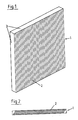
- the louvered ventilator 1 consists of several louver members i.e. slats or aerofoils 2.
- the slats are disposed in a vertical, upright position in a cascade arrangement.
- louvered ventilators can be 2 metres high and 2 - 3 metres wide.
- the slats are so arranged as partly to overlap one another.
- the distance between each slat is dependant upon the thickness of each slat as well as the requirement that the opening in the cascade which should be more than 70%.
- the slats are attached by means, (not shown), at their upper and lower ends, to a housing 3 by means of welding, a screw connection, a groove connection or the like.
- Fig. 3 depicts an example of a louver slat according to the invention in cross section.
- the drawing is to the scale 1:1, the numerals in the co-ordinates being in centimetre.
- the slat has a S-like shape and consists of an inlet part A, an inclining, intermediates part B, and an outlet part C.
- the inlet part A is connected to the intermediate part B through a first curved part 4, and the oulet part C is connected to the intermediate part B through a second curved part 5.
- the inlet part A and the outlet part C have their longitudinal axis essentially parallel with the normal for the ventilator (the co-ordinate x), and the intermediate part B forms an angle ⁇ with said normal of about 50°. Both the inlet part A and the outlet part C have rounded ends 6, 7 to prevent separation of the air passing through the ventilator.
- the louver slat is provided with longitudinally oriented canals or bores 8 which serves as drainage for the water deposited on the slat.
- These drain canals 8, which in Fig. 3 have a round or circular shape, are open towards the surface of the vertical member through a vertical slit 9. To prevent the water drops from passing over a slit 9, it has to be sufficiently wide. It is, however, not necessary to use round canals 8.
- the canals may be oval, rectangular or the like.
- slats shown in Fig. 3 fully complies with the previously mentioned requirements. It is, however, possible that some adjustments regarding the shape of the louver member may even improve these results.
- the length of the inlet A and outlet part C as shown in Fig. 3 may be varied as may the length of the intermediate part B or the angle ⁇ as shown in Fig. 3. It may also be possible to improve the results by positioning the canals 8 differently, or by altering the thickness of the louver slats.
- the slats 2 are preferably made of extruded aluminium profiles. However, other fabrication methods and materials may also be used.
Landscapes
- Engineering & Computer Science (AREA)
- Chemical & Material Sciences (AREA)
- Combustion & Propulsion (AREA)
- Mechanical Engineering (AREA)
- General Engineering & Computer Science (AREA)
- Specific Sealing Or Ventilating Devices For Doors And Windows (AREA)
- Ventilation (AREA)
Applications Claiming Priority (2)
| Application Number | Priority Date | Filing Date | Title |
|---|---|---|---|
| NO863739A NO160162C (no) | 1986-09-18 | 1986-09-18 | Anordning ved ventilasjonsvegg eller louver. |
| NO863739 | 1986-09-18 |
Publications (2)
| Publication Number | Publication Date |
|---|---|
| EP0260973A2 true EP0260973A2 (fr) | 1988-03-23 |
| EP0260973A3 EP0260973A3 (fr) | 1989-07-26 |
Family
ID=19889219
Family Applications (1)
| Application Number | Title | Priority Date | Filing Date |
|---|---|---|---|
| EP87308248A Withdrawn EP0260973A3 (fr) | 1986-09-18 | 1987-09-17 | Grille d'aération ressemblant à une persienne |
Country Status (2)
| Country | Link |
|---|---|
| EP (1) | EP0260973A3 (fr) |
| NO (1) | NO160162C (fr) |
Cited By (2)
| Publication number | Priority date | Publication date | Assignee | Title |
|---|---|---|---|---|
| EP0525966A1 (fr) * | 1991-06-18 | 1993-02-03 | H.H. Robertson (U.K.) Limited | Ventilateurs |
| US10173161B2 (en) * | 2006-04-05 | 2019-01-08 | Pfannenberg Gmbh | Filter fan for insertion in an opening in a wall of a casing of waste heat producing components |
Family Cites Families (2)
| Publication number | Priority date | Publication date | Assignee | Title |
|---|---|---|---|---|
| US2962956A (en) * | 1957-09-16 | 1960-12-06 | Acorn Advertisers | Ventilating louver assembly |
| IT1118938B (it) * | 1979-10-05 | 1986-03-03 | Fiat Ricerche | Persiana di ventilazione comprendente una pluralita di lamelle profilate |
-
1986
- 1986-09-18 NO NO863739A patent/NO160162C/no unknown
-
1987
- 1987-09-17 EP EP87308248A patent/EP0260973A3/fr not_active Withdrawn
Cited By (3)
| Publication number | Priority date | Publication date | Assignee | Title |
|---|---|---|---|---|
| EP0525966A1 (fr) * | 1991-06-18 | 1993-02-03 | H.H. Robertson (U.K.) Limited | Ventilateurs |
| AU651895B2 (en) * | 1991-06-18 | 1994-08-04 | Robertson (Australia) Pty Limited | Ventilators |
| US10173161B2 (en) * | 2006-04-05 | 2019-01-08 | Pfannenberg Gmbh | Filter fan for insertion in an opening in a wall of a casing of waste heat producing components |
Also Published As
| Publication number | Publication date |
|---|---|
| NO160162C (no) | 1989-03-15 |
| NO863739D0 (no) | 1986-09-18 |
| EP0260973A3 (fr) | 1989-07-26 |
| NO863739L (no) | 1988-03-21 |
| NO160162B (no) | 1988-12-05 |
Similar Documents
| Publication | Publication Date | Title |
|---|---|---|
| US6390914B1 (en) | Roof vent | |
| US10823451B2 (en) | Louver assembly | |
| US3782050A (en) | Louver assembly having improved weatherproofing and air flow characteristics | |
| US5149301A (en) | Baffle means for roof ridge ventilator | |
| US5254034A (en) | Adjustable width louver | |
| CN111819400A (zh) | 无动力换气件 | |
| US6138424A (en) | Vent apparatus for attachment to a building structure | |
| US4572059A (en) | Static ventilator construction | |
| GB2296321A (en) | Louver | |
| US20200284466A1 (en) | Air vent | |
| US4601136A (en) | Semicircular arching roof type pipe-frame greenhouse with monitor roof-like protrusion | |
| DE3463542D1 (en) | Ventilating element for building coverings | |
| EP0260973A2 (fr) | Grille d'aération ressemblant à une persienne | |
| CA2076959A1 (fr) | Systeme de ventilation passive | |
| US4167898A (en) | Illumination and ventilation system for buildings | |
| JP3390157B2 (ja) | 建物換気装置構造 | |
| CN105484474B (zh) | 设有防雨百叶的通风井结构 | |
| KR20120111560A (ko) | 루버용 블레이드 및 정류 루버 | |
| JP3207791B2 (ja) | 竪型防水ルーバ | |
| JP2567294B2 (ja) | 防水・防音ルーバー | |
| EP0436239A1 (fr) | Système de ventilation | |
| JPH0510009A (ja) | 屋根換気装置 | |
| JP3127132B2 (ja) | 棟換気ガラリ | |
| JPH11107439A (ja) | 通気ブロック | |
| CN212317806U (zh) | 铝合金百叶窗 |
Legal Events
| Date | Code | Title | Description |
|---|---|---|---|
| PUAI | Public reference made under article 153(3) epc to a published international application that has entered the european phase |
Free format text: ORIGINAL CODE: 0009012 |
|
| AK | Designated contracting states |
Kind code of ref document: A2 Designated state(s): DE FR GB NL SE |
|
| PUAL | Search report despatched |
Free format text: ORIGINAL CODE: 0009013 |
|
| AK | Designated contracting states |
Kind code of ref document: A3 Designated state(s): DE FR GB NL SE |
|
| RHK1 | Main classification (correction) |
Ipc: F24F 13/08 |
|
| STAA | Information on the status of an ep patent application or granted ep patent |
Free format text: STATUS: THE APPLICATION IS DEEMED TO BE WITHDRAWN |
|
| 18D | Application deemed to be withdrawn |
Effective date: 19900129 |
|
| RIN1 | Information on inventor provided before grant (corrected) |
Inventor name: SELJEBO, GUNNAR Inventor name: BAKKEN, TRYGVE |