EP0261087A2 - Dispositif de fermeture pour un battant de placard ou similaire - Google Patents
Dispositif de fermeture pour un battant de placard ou similaire Download PDFInfo
- Publication number
- EP0261087A2 EP0261087A2 EP87830329A EP87830329A EP0261087A2 EP 0261087 A2 EP0261087 A2 EP 0261087A2 EP 87830329 A EP87830329 A EP 87830329A EP 87830329 A EP87830329 A EP 87830329A EP 0261087 A2 EP0261087 A2 EP 0261087A2
- Authority
- EP
- European Patent Office
- Prior art keywords
- rod
- wing
- closet
- hook
- closure
- Prior art date
- Legal status (The legal status is an assumption and is not a legal conclusion. Google has not performed a legal analysis and makes no representation as to the accuracy of the status listed.)
- Granted
Links
- 230000008878 coupling Effects 0.000 claims abstract description 6
- 238000010168 coupling process Methods 0.000 claims abstract description 6
- 238000005859 coupling reaction Methods 0.000 claims abstract description 6
- 238000006073 displacement reaction Methods 0.000 abstract description 3
- 239000000463 material Substances 0.000 description 3
- 238000004519 manufacturing process Methods 0.000 description 2
- 238000000465 moulding Methods 0.000 description 2
- 239000002023 wood Substances 0.000 description 2
- 230000015572 biosynthetic process Effects 0.000 description 1
- 239000011093 chipboard Substances 0.000 description 1
- 238000010276 construction Methods 0.000 description 1
- -1 laminated boards Substances 0.000 description 1
- 239000004033 plastic Substances 0.000 description 1
- 229920003023 plastic Polymers 0.000 description 1
- 239000011120 plywood Substances 0.000 description 1
- 238000004513 sizing Methods 0.000 description 1
- 239000007787 solid Substances 0.000 description 1
Images

Classifications
-
- E—FIXED CONSTRUCTIONS
- E05—LOCKS; KEYS; WINDOW OR DOOR FITTINGS; SAFES
- E05C—BOLTS OR FASTENING DEVICES FOR WINGS, SPECIALLY FOR DOORS OR WINDOWS
- E05C9/00—Arrangements of simultaneously actuated bolts or other securing devices at well-separated positions on the same wing
- E05C9/08—Arrangements of simultaneously actuated bolts or other securing devices at well-separated positions on the same wing with a rotary bar for actuating the fastening means
Definitions
- This invention relates to a closure device for a wing of a closet and the like, of a type which comprises a closure hook cooperating with a striker on a post of said closet and being operated through a rod mounted to said wing.
- closets are widely used wherein the wing doors are locked closed by means of rods provided with hooks; by moving said rods angularly, each hook is brought to engage in a respective socket on the closet, thereby the wing door is held closed.
- Such a closure design is becoming increasingly more popular because it is the best for use with wing doors formed from wood-based materials other than solid wood, such as chipboards, laminated boards, plywood; these relatively inexpensive materials are, in fact, likely to buckle over time, and rod-and-hook closures resist buckling because, with the closet shut, they hold the wing doors under constant stress.
- closure devices including a small drive cylinder wherein a rotor is movable angularly by means of a key and is connected drivingly to a closure rod for driving the rod angularly.
- the closure rod and hook are generally a unitary construction, whereby the angular displacement of both the rod and the hook is accomplished by applying a torque to the rod through the complex linkage between said driving cylinder and the rod itself.
- a second prior approach provides for the use of less expensive, but still fairly complex closure devices; in fact, while being only comprised of simple and inexpensive parts, these are provided in such a high number as to make the resulting mechanism complicated and cumbersome.
- Other drawbacks come from that such prior closure devices are difficult to mount flush with the interior surface of a closet wing door and noisy in operation.
- a closure device for a wing of a closet and the like being of a type which comprises a closure hook cooperating with a striker on a post of said closet and driven by a rod mounted to said wing, and characterized in that said hook is associated with said rod by means of a screw and nut coupling operative to rotate said nut as said screw is shifted axially.
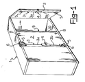
- the numeral 1 designates a closet, only depicted schematically, having a wing door 2 on whose inside there is mounted a closure rod 3.
- the rod 3 is split in two sections 3a and 3b aligned axially, and is driven linearly to move the two sections 3a and 3b axially toward and away from each other by a device, comprehensively designated 4, which is interposed to said sections 3a and 3b.
- each rod section, 3a or 3b is adapted to drive at least one closure hook angularly which engages with a respective striker to hold the wing 2 of the closet 1 shut.
- the strikers, indicated at 6, comprise, in the instance of a two-wing door, pegs attached to the closet 1 itself.
- Another example of this same striker, in the instance of a single wing door, is embodied by an offset hole 28 formed in a circular plate 8 which can be positioned adjustably and secured in place by means of a screw 31, respectively to oppositely located inside ends of a post 9 of the closet 1 in the vicinity of the outside abutment molding 10 of the post 9.
- each hook 5 will engage said hole 28, which is a square hole in the embodiment shown, from the inside.
- the device 4 is of a type known per se and comprises a small drive cylinder 7 which is accessible from the closet 1 outside through a hole formed in the wing 2.
- the cylinder 7 is provided with an internal rotor, not shown, which can be moved angularly by means of a key 11.
- Said device 4 is of a type commonly employed to drive said rod sections 3a and 3b toward and away from each other; for this purpose, the device 4 is provided with a pair of straps 12 and 13 connected drivingly to said rotor 9 by coupling means not shown and movable toward and away from each other. Said straps 12 and 13 are each provided with a pin 14 and 15, respectively, which extends perpendicularly thereto, being each adapted to engage with respective holes 16 and 17 formed at the ends 18 and 19 in each of said rod sections 3a and 3b.
- a yoke-like end fitting 21 which comprises, on one side, a screw segment 22, and on the other side, a guide pin 29.
- the screw 22 is coarse pitch one.
- a closure hook 5 is associated with each said ends 20 of the rod sections 3a and 3b via a screw and nut coupling between said coarse pitch screw 22 and a nut 23 formed in the body of the closure hook 5.
- Said coarse pitch screw 22 and said guide pin 29, forming the yoke on the end fitting 21, are carried movingly in a track 25 formed in a cylindrical insert 26 molded from a synthetic plastics material integrally with a mounting plate 30.
- Each closure hook 5 is pivoted to an insert 26 set flush with the wing 2 such that said track 25 is aligned axially to said yoke-like end fitting 21; said insert 26 is also formed with a slot 27 whereinto the closure hook 5 protrudes for angular movement.
- the device 4, rod 3, and both end fittings 21 are set flush inside grooves specially provided in the wing 2 and being hidden from view by an inside veneering of the wing 2 excepting at said insert 26 and mounting plate 30.
- the device according to the invention is operated as follows. On the rotor 9 of the drive cylinder 7 being moved angularly by means of the key 11, the straps 12 and 13 of the closure device 4 will cause the rod sections 3a and 3b to move toward or away from each other. In the vicinities of the opposed ends 20 of the rod 3 the linear motion of the rod sections 3a and 3b is converted to an angular displacement of the closure hooks 5 through the screw and nut coupling between the screw segment 22 of each end fitting 21, respectively connected to each end 20 of said rod sections 3a and 3b, and the nut formation 23 of each closure hook 5.
- each circular striker plate 8 for the hook 5 may be adjusted in position on the post 9 such that the wing 2 can fit snugly against the abutment molding 10 of the post 9 when closed.
- the primary evident advantage afforded by this invention is that the angular actuation of the closure hooks takes place at a location close to the hooks themselves, which enables a conventional closure device to be utilized as originally designed for a substantially latch-like linear movement of the rod sections 3a and 3b. This facilitates manufacturing and assembling the inventive device, which is also actually so compact as to allow the rods, and in part the closure hooks as well, to be set flush.
- the device according to this invention is then simple in design, it including a small number of component parts, and its operation is smooth and very quiet.
Landscapes
- Engineering & Computer Science (AREA)
- Mechanical Engineering (AREA)
- Power-Operated Mechanisms For Wings (AREA)
- Closing And Opening Devices For Wings, And Checks For Wings (AREA)
- Securing Of Glass Panes Or The Like (AREA)
- Paper (AREA)
- Specific Sealing Or Ventilating Devices For Doors And Windows (AREA)
- Supports Or Holders For Household Use (AREA)
- Toilet Supplies (AREA)
- Hooks, Suction Cups, And Attachment By Adhesive Means (AREA)
Priority Applications (1)
| Application Number | Priority Date | Filing Date | Title |
|---|---|---|---|
| AT87830329T ATE66273T1 (de) | 1986-09-17 | 1987-09-15 | Verschlussvorrichtung fuer einen wandschrankfluegel oder dergleichen. |
Applications Claiming Priority (2)
| Application Number | Priority Date | Filing Date | Title |
|---|---|---|---|
| IT8623086U IT208044Z2 (it) | 1986-09-17 | 1986-09-17 | Dispositivo di chiusura per una anta di un armadio e simili. |
| IT2308686U | 1986-09-17 |
Publications (3)
| Publication Number | Publication Date |
|---|---|
| EP0261087A2 true EP0261087A2 (fr) | 1988-03-23 |
| EP0261087A3 EP0261087A3 (en) | 1988-11-09 |
| EP0261087B1 EP0261087B1 (fr) | 1991-08-14 |
Family
ID=11203629
Family Applications (1)
| Application Number | Title | Priority Date | Filing Date |
|---|---|---|---|
| EP87830329A Expired EP0261087B1 (fr) | 1986-09-17 | 1987-09-15 | Dispositif de fermeture pour un battant de placard ou similaire |
Country Status (6)
| Country | Link |
|---|---|
| EP (1) | EP0261087B1 (fr) |
| AT (1) | ATE66273T1 (fr) |
| DE (1) | DE3772138D1 (fr) |
| ES (1) | ES2001843A4 (fr) |
| GR (1) | GR880300160T1 (fr) |
| IT (1) | IT208044Z2 (fr) |
Cited By (1)
| Publication number | Priority date | Publication date | Assignee | Title |
|---|---|---|---|---|
| DE19946773A1 (de) * | 1999-09-29 | 2001-05-23 | Loh Kg Rittal Werk | Schliesseinrichtung für einen Schaltschrank |
Family Cites Families (3)
| Publication number | Priority date | Publication date | Assignee | Title |
|---|---|---|---|---|
| DE7217639U (de) * | 1972-08-03 | Knapp A | Drehhakenverschluß, insbesondere für Möbeltüren | |
| DE6606124U (de) * | 1967-08-23 | 1970-08-20 | Weber & Co | Drehriegel-verschluss |
| DE6901382U (de) * | 1969-01-13 | 1969-05-22 | Vogt Bueromoebel | Stangenschloss |
-
1986
- 1986-09-17 IT IT8623086U patent/IT208044Z2/it active
-
1987
- 1987-09-15 ES ES87830329T patent/ES2001843A4/es active Pending
- 1987-09-15 AT AT87830329T patent/ATE66273T1/de not_active IP Right Cessation
- 1987-09-15 EP EP87830329A patent/EP0261087B1/fr not_active Expired
- 1987-09-15 DE DE87830329T patent/DE3772138D1/de not_active Expired - Fee Related
-
1989
- 1989-01-31 GR GR88300160T patent/GR880300160T1/el unknown
Cited By (2)
| Publication number | Priority date | Publication date | Assignee | Title |
|---|---|---|---|---|
| DE19946773A1 (de) * | 1999-09-29 | 2001-05-23 | Loh Kg Rittal Werk | Schliesseinrichtung für einen Schaltschrank |
| DE19946773C2 (de) * | 1999-09-29 | 2003-06-05 | Rittal Gmbh & Co Kg | Schliesseinrichtung für einen Schaltschrank |
Also Published As
| Publication number | Publication date |
|---|---|
| ES2001843A4 (es) | 1988-07-01 |
| IT8623086V0 (it) | 1986-09-17 |
| EP0261087B1 (fr) | 1991-08-14 |
| GR880300160T1 (en) | 1989-01-31 |
| DE3772138D1 (en) | 1991-09-19 |
| EP0261087A3 (en) | 1988-11-09 |
| IT208044Z2 (it) | 1988-03-31 |
| ATE66273T1 (de) | 1991-08-15 |
Similar Documents
| Publication | Publication Date | Title |
|---|---|---|
| US3737184A (en) | Push button latch mechanism | |
| US6161881A (en) | Casement lock | |
| JP3193723B2 (ja) | ドアラッチアクチュエータ | |
| US3655230A (en) | Door latch | |
| US5951068A (en) | Lock for sliding door | |
| US3653154A (en) | Door actuator | |
| US11959307B2 (en) | Lever action automatic shootbolt operator with magnetically-triggered locking mechanism | |
| AU637296B2 (en) | Motor vehicle door lock controlling device | |
| CA2113694A1 (fr) | Actionneur de verrou, motorise, pour serrure cylindrique | |
| DE112009000529T5 (de) | Schloss mit drehbarer Sperrklinke | |
| SE9401093L (sv) | Mekanism för låsning av en lucka | |
| AU2931989A (en) | Locking device | |
| AU2023233054A1 (en) | Lever action automatic shootbolt operator with magnetically-triggered locking mechanism | |
| EP0261087B1 (fr) | Dispositif de fermeture pour un battant de placard ou similaire | |
| GB2161201A (en) | Fastening mechanism for doors or windows | |
| CS271304B2 (en) | Fittings for windows,doors etc. | |
| ATE190109T1 (de) | Selbstverriegelnde verschlussvorrichtung für türen oder dergleichen | |
| EP1053376B1 (fr) | Structures de securite ameliorees | |
| EP0374351B1 (fr) | Verrou réglable pour fermetures de battants de portes coulissantes ou de fenêtres ou similaires | |
| FR2250370A5 (en) | Lock actuated by casement bolt - has bolt with sliding connection to actuator plate coupled to casement bolt | |
| US20220162882A1 (en) | Lever action automatic shootbolt operator with magnetically-triggered lock mechanism | |
| EP0497580A2 (fr) | Mécanisme de verrouillage de fermeture | |
| AU701778C (en) | Lock for sliding door | |
| WO2023154054A1 (fr) | Actionneur de pêne coulissant automatique à action de levier comprenant un mécanisme de verrouillage à déclenchement magnétique | |
| DE59607657D1 (de) | Mehrfachverriegelungsanlage |
Legal Events
| Date | Code | Title | Description |
|---|---|---|---|
| PUAI | Public reference made under article 153(3) epc to a published international application that has entered the european phase |
Free format text: ORIGINAL CODE: 0009012 |
|
| AK | Designated contracting states |
Kind code of ref document: A2 Designated state(s): AT BE CH DE ES FR GB GR LI LU NL SE |
|
| EL | Fr: translation of claims filed | ||
| TCAT | At: translation of patent claims filed | ||
| PUAL | Search report despatched |
Free format text: ORIGINAL CODE: 0009013 |
|
| DET | De: translation of patent claims | ||
| AK | Designated contracting states |
Kind code of ref document: A3 Designated state(s): AT BE CH DE ES FR GB GR LI LU NL SE |
|
| 17P | Request for examination filed |
Effective date: 19881118 |
|
| 17Q | First examination report despatched |
Effective date: 19891130 |
|
| GRAA | (expected) grant |
Free format text: ORIGINAL CODE: 0009210 |
|
| AK | Designated contracting states |
Kind code of ref document: B1 Designated state(s): AT BE CH DE ES FR GB GR LI LU NL SE |
|
| PG25 | Lapsed in a contracting state [announced via postgrant information from national office to epo] |
Ref country code: SE Effective date: 19910814 Ref country code: LI Effective date: 19910814 Ref country code: GR Free format text: LAPSE BECAUSE OF FAILURE TO SUBMIT A TRANSLATION OF THE DESCRIPTION OR TO PAY THE FEE WITHIN THE PRESCRIBED TIME-LIMIT Effective date: 19910814 Ref country code: CH Effective date: 19910814 Ref country code: BE Effective date: 19910814 Ref country code: AT Effective date: 19910814 |
|
| REF | Corresponds to: |
Ref document number: 66273 Country of ref document: AT Date of ref document: 19910815 Kind code of ref document: T |
|
| REF | Corresponds to: |
Ref document number: 3772138 Country of ref document: DE Date of ref document: 19910919 |
|
| PG25 | Lapsed in a contracting state [announced via postgrant information from national office to epo] |
Ref country code: LU Free format text: LAPSE BECAUSE OF NON-PAYMENT OF DUE FEES Effective date: 19910930 |
|
| PG25 | Lapsed in a contracting state [announced via postgrant information from national office to epo] |
Ref country code: GB Effective date: 19911114 |
|
| PG25 | Lapsed in a contracting state [announced via postgrant information from national office to epo] |
Ref country code: ES Free format text: LAPSE BECAUSE OF FAILURE TO SUBMIT A TRANSLATION OF THE DESCRIPTION OR TO PAY THE FEE WITHIN THE PRESCRIBED TIME-LIMIT Effective date: 19911125 |
|
| REG | Reference to a national code |
Ref country code: CH Ref legal event code: PL |
|
| EN | Fr: translation not filed | ||
| PG25 | Lapsed in a contracting state [announced via postgrant information from national office to epo] |
Ref country code: FR Effective date: 19920103 |
|
| PG25 | Lapsed in a contracting state [announced via postgrant information from national office to epo] |
Ref country code: NL Effective date: 19920401 |
|
| NLV4 | Nl: lapsed or anulled due to non-payment of the annual fee | ||
| PG25 | Lapsed in a contracting state [announced via postgrant information from national office to epo] |
Ref country code: DE Effective date: 19920602 |
|
| PLBE | No opposition filed within time limit |
Free format text: ORIGINAL CODE: 0009261 |
|
| STAA | Information on the status of an ep patent application or granted ep patent |
Free format text: STATUS: NO OPPOSITION FILED WITHIN TIME LIMIT |
|
| GBPC | Gb: european patent ceased through non-payment of renewal fee | ||
| 26N | No opposition filed | ||
| REG | Reference to a national code |
Ref country code: FR Ref legal event code: ST |