EP0261261A1 - Machine-outil - Google Patents
Machine-outil Download PDFInfo
- Publication number
- EP0261261A1 EP0261261A1 EP86113064A EP86113064A EP0261261A1 EP 0261261 A1 EP0261261 A1 EP 0261261A1 EP 86113064 A EP86113064 A EP 86113064A EP 86113064 A EP86113064 A EP 86113064A EP 0261261 A1 EP0261261 A1 EP 0261261A1
- Authority
- EP
- European Patent Office
- Prior art keywords
- tool
- tool carrier
- change ring
- ring
- change
- Prior art date
- Legal status (The legal status is an assumption and is not a legal conclusion. Google has not performed a legal analysis and makes no representation as to the accuracy of the status listed.)
- Granted
Links
- 239000000969 carrier Substances 0.000 claims abstract description 215
- 238000012545 processing Methods 0.000 claims abstract description 80
- 230000008878 coupling Effects 0.000 claims abstract description 68
- 238000010168 coupling process Methods 0.000 claims abstract description 68
- 238000005859 coupling reaction Methods 0.000 claims abstract description 68
- 230000008859 change Effects 0.000 claims description 205
- 238000003754 machining Methods 0.000 claims description 29
- 210000000078 claw Anatomy 0.000 claims description 28
- 238000013016 damping Methods 0.000 claims description 10
- 230000032258 transport Effects 0.000 claims description 8
- 238000012432 intermediate storage Methods 0.000 claims description 4
- 238000001816 cooling Methods 0.000 claims description 3
- 238000010438 heat treatment Methods 0.000 claims description 3
- 239000010687 lubricating oil Substances 0.000 claims description 3
- 230000036316 preload Effects 0.000 claims description 2
- 238000003860 storage Methods 0.000 description 20
- 239000000872 buffer Substances 0.000 description 6
- 238000013461 design Methods 0.000 description 6
- 230000001154 acute effect Effects 0.000 description 5
- 238000006073 displacement reaction Methods 0.000 description 5
- 239000010720 hydraulic oil Substances 0.000 description 5
- 230000008901 benefit Effects 0.000 description 4
- 238000006243 chemical reaction Methods 0.000 description 4
- 238000007789 sealing Methods 0.000 description 4
- 238000003801 milling Methods 0.000 description 3
- 230000001105 regulatory effect Effects 0.000 description 3
- 238000012360 testing method Methods 0.000 description 3
- 239000006096 absorbing agent Substances 0.000 description 2
- 230000005540 biological transmission Effects 0.000 description 2
- 238000010276 construction Methods 0.000 description 2
- 238000000151 deposition Methods 0.000 description 2
- 238000005553 drilling Methods 0.000 description 2
- 239000003921 oil Substances 0.000 description 2
- 230000035939 shock Effects 0.000 description 2
- 238000012546 transfer Methods 0.000 description 2
- 241001136792 Alle Species 0.000 description 1
- 229910001018 Cast iron Inorganic materials 0.000 description 1
- 229910000831 Steel Inorganic materials 0.000 description 1
- 239000003570 air Substances 0.000 description 1
- 230000006835 compression Effects 0.000 description 1
- 238000007906 compression Methods 0.000 description 1
- 239000000498 cooling water Substances 0.000 description 1
- 238000009795 derivation Methods 0.000 description 1
- 238000011161 development Methods 0.000 description 1
- 230000018109 developmental process Effects 0.000 description 1
- 230000000694 effects Effects 0.000 description 1
- 238000011031 large-scale manufacturing process Methods 0.000 description 1
- 238000012423 maintenance Methods 0.000 description 1
- 238000004519 manufacturing process Methods 0.000 description 1
- 238000005259 measurement Methods 0.000 description 1
- 239000007769 metal material Substances 0.000 description 1
- 238000000034 method Methods 0.000 description 1
- 239000000256 polyoxyethylene sorbitan monolaurate Substances 0.000 description 1
- 230000000284 resting effect Effects 0.000 description 1
- 230000000630 rising effect Effects 0.000 description 1
- 238000005096 rolling process Methods 0.000 description 1
- 238000007790 scraping Methods 0.000 description 1
- 239000010959 steel Substances 0.000 description 1
- 239000000725 suspension Substances 0.000 description 1
Images














Classifications
-
- B—PERFORMING OPERATIONS; TRANSPORTING
- B23—MACHINE TOOLS; METAL-WORKING NOT OTHERWISE PROVIDED FOR
- B23Q—DETAILS, COMPONENTS, OR ACCESSORIES FOR MACHINE TOOLS, e.g. ARRANGEMENTS FOR COPYING OR CONTROLLING; MACHINE TOOLS IN GENERAL CHARACTERISED BY THE CONSTRUCTION OF PARTICULAR DETAILS OR COMPONENTS; COMBINATIONS OR ASSOCIATIONS OF METAL-WORKING MACHINES, NOT DIRECTED TO A PARTICULAR RESULT
- B23Q3/00—Devices holding, supporting, or positioning work or tools, of a kind normally removable from the machine
- B23Q3/155—Arrangements for automatic insertion or removal of tools, e.g. combined with manual handling
- B23Q3/157—Arrangements for automatic insertion or removal of tools, e.g. combined with manual handling of rotary tools
-
- B—PERFORMING OPERATIONS; TRANSPORTING
- B23—MACHINE TOOLS; METAL-WORKING NOT OTHERWISE PROVIDED FOR
- B23Q—DETAILS, COMPONENTS, OR ACCESSORIES FOR MACHINE TOOLS, e.g. ARRANGEMENTS FOR COPYING OR CONTROLLING; MACHINE TOOLS IN GENERAL CHARACTERISED BY THE CONSTRUCTION OF PARTICULAR DETAILS OR COMPONENTS; COMBINATIONS OR ASSOCIATIONS OF METAL-WORKING MACHINES, NOT DIRECTED TO A PARTICULAR RESULT
- B23Q3/00—Devices holding, supporting, or positioning work or tools, of a kind normally removable from the machine
- B23Q3/155—Arrangements for automatic insertion or removal of tools, e.g. combined with manual handling
- B23Q2003/1558—Arrangements for automatic insertion or removal of tools, e.g. combined with manual handling involving insertion or removal of other machine components together with the removal or insertion of tools or tool holders
Definitions
- the invention relates to a processing machine with a device for changing a tool carrier, in which the entire tool carrier can be removed from a processing position and can be exchanged for at least one other tool carrier, with a motor drive unit, a drive unit designed as a rotating ring that can be rotated about a vertical axis ring-shaped and together with the drive unit between a machining position and a tool change position longitudinally displaceable tool changing device, the change ring having receiving couplings for coupling and uncoupling the tool carrier and the change ring on its circumference preferably several such receiving couplings for coupling and uncoupling from Z.
- the drive unit having at least one energy supply device for driving the tool carrier in the working position and at least one receiving and tensioning element for fixing, tensioning and possibly driving the tool carrier in the working position, the drive unit on a slide, and the change ring is preferably arranged on an auxiliary slide and this is movable relative to this slide, and the change ring is rotatable about its vertical axis of rotation and the auxiliary slide in a predetermined end position allows the change ring to stand still by opposite horizontal movement of the auxiliary slide and that the change ring is relative to the tool carriers to be accommodated allow a vertical lifting movement of the interchangeable ring itself and / or the tool carrier in two opposite vertical directions.
- At least one angle lever with at least one roller is arranged below the change ring, the angle lever being connected to a coupling rod with an auxiliary slide assigned to the slide and guided longitudinally displaceably therewith, the roller running into a control cam in an end position, such that in a predetermined position End position of the auxiliary slide the change ring relative to the direction of displacement of the slide by opposite movement of the auxiliary slide can stand still, the interchangeable ring by suitably arranged groove-like curves in the auxiliary slide or the like with locally attached guide elements, e.g. B. rolls, a lifting movement is given in two opposite directions, two or more groove-like curves over a part of their length, in particular at 45 degrees, are arranged parallel to each other.
- a vertical guide serving as the Y axis is assigned to the drive unit.
- the processing machine described above adapts to different flexibility requirements depending on the processing task, workpiece range and annual production. It can be expanded and converted, which applies both to the machine itself and to its control and interlinking.
- a device according to the invention can accordingly as a single machine or within a linked system or as an assembly, for. B. integrate within a transfer line.
- the tool carriers can be exchanged automatically within a machining cycle or semi-automatically or manually when changing over, depending on the requirements. There is no system limitation to a certain number of tool carriers. The change system is open or unlimited regardless of the size of the tool carrier and their number. The short access times and short chip-to-chip times are important in all cases.
- Another advantage is the good accessibility for the tool change and the good accessibility for maintenance.
- such a device can be built very compactly, and it is easily possible to set up the device for machining in the X and Y axes.
- deep drilling operations, facing operations and testing operations are possible with such a device.
- the changing system is not subject to high accuracy requirements, because only a certain tool carrier in the working position is picked up and coupled by the drive unit. Therefore, the required accuracy only needs to be established in this position, not against it for the tool carrier, which is in the storage position, for. B. around the drive unit.
- the change ring surrounds the drive unit in a ring shape makes the device extremely compact. Due to the special type of lifting and sliding movement that are carried out when changing tool carriers with such a device, extremely short idle times result, so that such a device can be used with particular advantage in large-scale production, for example in the automotive industry.
- the invention has for its object to improve or further develop a processing unit according to the type attributed to the applicant.
- the technical Application range enlarged and further solutions according to the invention are shown.
- the tool carrier is automatically decoupled from the drive unit before reaching the end position and taken over by receiving holders of the interchangeable ring.
- the auxiliary slide bumps against a fixed stop which, for. B. can be designed as a roller, ball, plunger, buffer, shock absorber, shock absorber or the like.
- the auxiliary slide under spring tension is always pushed into the end position.
- slotted guide grooves with horizontal sections and parts opening downward at 45 degrees are provided on one or both sides, into which rollers or the like attached to the slide engage.
- auxiliary slide now bumps against the undamped (rigid) or damped stop, then the auxiliary slide is pressed against the spring force of e.g. B. displaced as a compression spring element.
- the spring force e.g. B. displaced as a compression spring element.
- the surfaces guided on one another can be equipped with a friction-reducing covering or at least some of them with a roller, a ball or the like, so that the vertical lifting movement of the auxiliary slide is also related there are no significant frictional forces on the fixed or damped stop and no damage occurs. Because the auxiliary sled is coupled with the change ring, the movements are coordinated so that the change ring remains relatively still as soon as it has started against the rigid or against the damped stop located in the end position.
- auxiliary slide moves against the stop of the built-in damping when the tool carrier tension is open.
- the auxiliary slide with interchangeable ring and tool holder is slowed down to a standstill with an adjustable or controlled (regulated) damping.
- the further movement of the processing slide causes a vertical lifting movement of the auxiliary slide over the backdrop curves already described.
- the horizontal relative movement takes place via a fixed or damped stop of the longitudinally displaceable auxiliary slide and the vertical relative movement of the change ring and the auxiliary slide with respect to the tool carriers only by raising or lowering the tool carriers themselves and / or the tool carrier trays, no longer by a stroke of the interchangeable ring with its auxiliary slide.
- the change ring itself can be designed without a vertical stroke.
- the tool carrier is tensioned to the drive unit directly via the change ring, the clamping forces going via the change ring bearing.
- the tool carriers are tensioned via the slide unit or via the drive unit, but not directly via the change ring.
- the change ring only absorbs reaction forces.
- the tension can take place directly on the change ring at the front, while only reaction forces are transferred to the change ring bearing.
- the clamping and fixing of the tool carrier is carried out by means of one or two clamping levers from the drive unit directly on the relevant tool carrier in the working position. This results in a new two-point clamping directly from the drive unit to the tool holder.
- Claim 8 describes an embodiment in which the interchangeable ring is provided with only two supports and fixing bolts and two receiving holders for receiving the tool carriers in the interchangeable ring. This creates new holders for the tool holder and interchangeable ring.
- the receiving claws can also take over clamping functions.
- a plurality of drive clutches are provided for the tool holder in each case in the working position.
- Such can e.g. B. be advantageous to a z. B. to drive a slide valve and / or to insert a quill, and / or to pivot a test device.
- more than four tool carriers on the change ring z. B. six tool carriers arranged. All tool carriers, e.g. B. six, always remain on the interchangeable ring, ie there are no shelves.
- One tool holder is always in the working position, while the other five tool holders are arranged on the change ring. Only the tool carrier in the working position is fixed, clamped and supplied with energy, so it needs to be arranged with the required accuracy.
- the complete interchangeable ring with the tool carriers located on it is replaced as a complete structural unit, e.g. B. offset by a hoist and exchanged with another completely designed changing ring with other tool carriers, or mechanically via a changing device.
- Claim 13 describes an embodiment in which the change ring a magazine with z. B. is assigned to ten tool carriers, which are fed to the change ring controlled by roller conveyors.
- the interchangeable ring passes under the tool carrier concerned, hangs it in and lifts it off.
- the workpiece can be fed on a pallet on a slide from pallet parking spaces.
- the change ring is a single magazine with z. B. assigned ten tool carriers.
- the single magazine can also be provided as a multiple magazine with the same or a different number of tool carriers.
- This multiple magazine can be provided on one side - on the head side - of the interchangeable ring, while on the diametrically opposite side a slide with slide drive is provided around pallet parking spaces, on which the workpieces are fed to the tool carriers.
- a single magazine is mounted across and z. B. provided with eight tool carriers in the magazine and ten to twelve tool carriers in total. The return can take place directly behind the processing machine.
- this construction is e.g. B. expandable in a double magazine.
- An indexing table with 6 x 60 ° for six tool carriers can be provided.
- Claim 20 includes a revolving oval magazine for z. B. sixteen, a total of twenty tool carriers and random access to the tool carriers.
- Claim 21 describes a transverse oval magazine for optional access.
- Claim 24 describes a high rack with a shelf conveyor and a buffer in cooperation with a processing machine according to the invention. However, this embodiment also works without a buffer.
- a double-sided high rack is provided, between which a rack conveyor is arranged, with an intermediate store.
- a double-sided high rack with a central shelf conveyor and a swivel and slide station and an intermediate store is assigned to a processing machine according to the invention, while in the embodiment according to claim 27 a high rack system is provided for converting various magazines of the designs described above.
- a high rack with a rack vehicle is provided with magazines interposed between a processing machine according to the invention and the rack vehicle, these magazines from the high rack warehouse being able to be converted by automatically changing tool carriers.
- a longitudinal magazine with shunting tracks and additional parking spaces is available.
- additional parking spaces for example, tool carriers can be placed cooled or heated, for example in order to be able to maintain very precise spacing dimensions when multi-spindle precision turning.
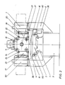
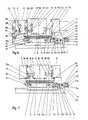
- Reference number 1 denotes a slide guide which is arranged horizontally in the embodiment shown and in which a slide 2 is guided in the direction D or E so as to be longitudinally displaceable (stroke).
- the slide guide 1 and slide 2 form a slide unit.
- an auxiliary slide that is movable relative to the slide 2 in the longitudinal direction thereof is arranged.
- the reference numeral 3 designates a stationary substructure in the illustrated embodiment, on which the slide guide 1 is arranged.
- the reference numerals 4, 5 and 6 denote three tool holder trays which are arranged on the substructure 3.
- the one tool carrier tray 5 is arranged in one end region of the slide guide 1, while one of the tool carrier trays 4 and 6 is located on diametrically opposite sides of the slide guide 1, specifically outside the vertical projection of the slide 2, however in the immediate vicinity of it.
- a tool carrier 7 or 8 is arranged on the tool carrier tray 5 and on the tool carrier tray 6, while the tool carrier tray 4 in this embodiment (FIG. 2) does not accept a tool carrier in the assumed example.
- a tool carrier 50 can also be arranged here.
- a further tool carrier 9 is in the working position on a drive unit 10, to which a DC drive 11 is assigned in the embodiment shown.
- Tool carrier 9 and drive unit 10 with DC drive 11 together form an overall movable group or structural unit.
- tools are indicated by dash-dotted lines and designated by 12, 13 and 14. These can e.g. B. drills or milling cutters. Any number of such tools can be provided, so that the tool carriers 7, 8, 9 and 50 multi-spindle heads, e.g. B. multi-spindle drilling heads.
- the drawing also shows that the tool carriers 7, 8, 9 and 50 are block-shaped and designed as a total of interchangeable units, which have an approximately rectangular shape in plan view in all the embodiments shown, but also z. B. square, cube-shaped or in any other suitable manner, for. B. polygonal, can be shaped.
- a tool holder can e.g. B. have a weight of one or more tons.
- the interchangeable ring 15 has receptacles 17, 18, 19 and 20 which are integrally connected to it and protrude vertically upwards and extend parallel to the axis of rotation 16 and which, in this embodiment, have an approximately plan view have a triangular shape and extend approximately to the upper edge of the drive unit 10.
- Interchangeable ring 15 and holder 17, 18, 19 and 20 are designed in one piece in this embodiment and consist of a metallic material, in particular steel or cast iron.
- the receptacle holders 17, 18, 19 and 20 each have a plurality of receptacle couplings in mutually offset, outwardly facing planes, of which only the couplings 21 to 31 are provided with reference numerals.
- Figures 1 to 9 clearly show that on each holder 17 to 20 several couplings - in this case in pairs - are arranged in different height ranges.
- These receiving couplings 21 to 31 correspond to suitable abutments which are provided on the tool carriers 7, 8, 9 and 50. These abutments were made for better reasons Overview in Fig. 1 only the abutment 32 provided with reference numerals.
- the remaining abutments 32 of the tool carrier 7, 8, 9 can be designed accordingly, such that they can be brought into and out of engagement with the associated receiving couplings 21 to 31.
- the drive unit 10 has a central energy supply 33, via which the tool carrier in the working position, in this case the tool carrier 9 and its tools 14, are to be supplied with drive energy. Furthermore, the drive unit 10 has receiving and fixing elements 34, 35, 36 and 37 for the tool carriers, via which the tool carrier in the working position, in the present case 9, is fixed and clamped.
- the reference numeral 38 denotes a motor drive for the change ring 15.
- the motor drive 38 drives a pinion, not shown in detail, which meshes with a ring gear 39 which is integrally connected to the change ring 15, such that the change ring 15 is infinitely drivable in both directions of rotation.
- the change ring 15 is guided on the circumference by rollers having vertical axes of rotation in the embodiment shown, of which the rollers 40 and 41 can be seen from FIG. 1. A plurality of such rollers 40 and 41 can be distributed with respect to one another over the circumference of the change ring 15.
- the reference numeral 42 designates in Fig. 1 an angle lever, one lever arm of which is pivotally mounted on the slide 2 in the vertical plane via an axis 43. With the angle lever 42, a coupling rod 44 is pivotally coupled via an axis 45, also in the vertical plane. The coupling rod 44 is connected at its end remote from the angle lever 42 via a pivot axis 46 to a coupling 47 which is associated with the auxiliary slide 62.
- the reference numeral 49 denotes a roller which is arranged at the end of the angle lever 42 and which projects over the slide 2.
- 48 and 48a denote slotted guide grooves rising at an angle of 45 degrees, which are arranged on both sides of the auxiliary slide 62 and which engage rollers arranged on each side of the device on the slide 2, of which the rollers 60 and 61 can be seen from FIG. 1 .
- 63 denotes a downward-curved control cam with an enlarged inlet into which the roller 49 is able to run.
- the angle lever 42 together with the control cam 63 and the guide grooves 48 and 48a enable the tool carriers 7, 8, 9 and 50 to be picked up or moved apart to the drive unit 10 or to be deposited at the storage stations for the tool carriers with the aid of the change ring 15. If the roller 49 runs into the cam 63, it is pivoted downwards when the downwardly curved part of the curve is reached, as a result of which the auxiliary slide 62 via the angle lever 42, the coupling rod 44 opposes it to the direction of movement E, that is, relative to the carriage 2.
- a horizontal movement of the change ring 15 initially takes place via the horizontal curve sections or guide grooves 48, 48a, while when the inclined curve part of the guide grooves 48 and 48a is reached, the change ring 15 is moved in direction A, that is to say carries out a vertical upward stroke.
- the arrangement is such that when entering the oblique part of the curve extending at 45 degrees in the illustrated embodiment, the interchangeable ring 15 stands still with respect to the tool carrier trays 4, 5 and 6 for the tool carriers 7, 8 and 9 and 50, respectively.
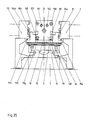
- the starting point for the machining sequence is the representation according to FIG. 1, in which the tool carrier 9 is in a machining position.
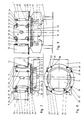
- FIGS. 4, 5 and 6 again show the so-called processing position of the processing machine and the tool carrier coupled in the working position
- FIGS. 7 to 9 illustrate the same processing machine, in a position in which the Changing ring 15 has the tool carrier 7, 8, 9, 50 coupled and raised, ie the changing ring 15, the drive unit 10 and the direct current drive 11 and the coupled tool carrier 7, 8, 9 and 50 have performed a vertical stroke A upwards, so that this entire unit can now be rotated (pivoted) in one direction or the other.
- This means that the pivoting position of the processing machine is illustrated in FIGS. 7 to 9.
- the interchangeable ring was used to hold four tool carriers 7, 8, 9 and 50 at the most.
- An auxiliary slide 62 with interchangeable ring bearings via rollers 40, 41 is present.
- the interchangeable ring 15 is displaceable relative to the drive unit 10 and horizontally and vertically via entry curves (scenes) by means of levers and push rods as well as guide curves in the auxiliary slide 62.
- the auxiliary slide 62 is preloaded relative to the slide 2 by gas pressure springs. There is a horizontal relative movement for uncoupling and coupling the tool carriers 7, 8, 9 and 50, and the drives, the media supply (cooling water, air, oil, etc.) as well as the signal and data transmission systems.
- a vertically arranged abutment 65 is connected to the substructure 3, which has a stop 66 with a roller 67 or the like, which can be rotated as desired in a cage of the stop 66 and is directed in the direction of the auxiliary slide 62 pops out.
- the auxiliary carriage 62 is constantly pushed and biased by a spring element 68, which is only schematically indicated, in the direction E.
- the spring element 68 is supported on the carriage 2 with another end.
- the spring element 68 can be a gas pressure spring, a plate spring, a helical spring or consist of several spring elements.
- the relative movement of the change ring 15 and the drive unit 10 with the DC drive 11, not shown, is produced differently in relation to the slide 2 and in relation to the tool carrier trays 3, 4, 5 and 6.
- the tool carriers 7, 8, 50 are also on their tool carrier trays 4, 5, 6.
- Carriage 2 and auxiliary carriages 62 are also motorized in direction E as in the embodiment according to FIGS. 1 to 9 with the coupled tool carrier 9, the drive unit 10 and the change ring 15 retracted.
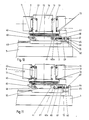
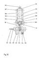
- the tool carrier 9 is automatically decoupled from the drive unit 10 and taken over by two receiving holders 17 to 20 of the change ring 15, which is illustrated in FIG. 10.
- the auxiliary carriage 62 abuts against the roller 67 of the stop 66, as a result of which the auxiliary carriage 62 relative to the carriage 2 is relatively displaced, such that the interchangeable ring 15 with the drive unit 10 and the direct current motor 11 and the coupled tool holder 9 remains stationary.
- the rollers 60, 61 slide in the associated link-like guide grooves 48 and 48a, specifically in their horizontal sections (FIG. 10).
- the subsequent vertical stroke of the change ring 15 in direction A with the coupled tool carriers 7, 8, 9 and 50 takes place as soon as the rollers 40, 41 enter the guide groove sections arranged at an acute angle to the horizontal guide grooves 48 and 48a.
- the spring element 68 is compressed to the position shown in FIG. 11.
- a vertical relative movement takes place between the spherical body 67 and the auxiliary slide 62.
- the spring element 68 can also be supported on the auxiliary slide 62 in a rolling manner via a guide sleeve 69 and a roller 70 arranged in this, since the vertical stroke in direction A or T also applies here a relative movement occurs which should be designed with as little friction as possible.
- the interchangeable ring 15 is rotated by 90 degrees by motor, as in the embodiment according to FIGS. 1 to 9, including tool carriers 7, 8, 9 and 50.
- the carriage 2 is moved back in the direction D by motor, the change ring 15 during this movement in the direction D of the carriage 2 performing a downward stroke, that is to say in the direction T, z. B.
- the tool carriers 7, 8, 9 are placed on the tool carrier trays 4, 5 and 6, while the tool carrier 50 is lowered for receiving.
- the tool carrier 50 is taken over by the drive unit 10, ie fixed, clamped and coupled. Thereupon, this tool carrier 50 is in the working position as in the embodiment according to FIGS. 1 to 9.
- the rollers 60 and 61 slide up again in the guide grooves 48 and 48a and then into the horizontal sections (FIG.
- an abutment 65 is again provided which has a stop 66 with a roller 67 against which the auxiliary slide 62 can abut in its end position, so that a horizontal relative movement between slide 2 and auxiliary slide 62 takes place.
- a piston-cylinder unit 73 can be alternately acted upon on both sides with pressure medium pressure, in particular with hydraulic oil, the cylinder 75 of which is coupled to the auxiliary slide 62 via a horizontal pivot axis 74, the longitudinal axis of which is transverse, ie normal to the direction of movement DE of the carriage 2 (at right angles).
- a piston 76 is guided in a longitudinally displaceable and sealing manner in the cylinder 75.
- a piston rod 77 is sealed out of the cylinder 75 and via a pivot axis 78, the longitudinal axis of which runs parallel to the longitudinal axis of the axis 74 and is connected to a fixed abutment on the slide 2, so that the piston-cylinder unit 73 can be pivoted in the vertical plane is arranged.
- the horizontal relative movement which allows the unit consisting of the interchangeable ring 15, drive unit 10, direct current drive 11 and tool holder 9, for example, to stand still relative to the slide 2, is again achieved by the auxiliary slide 62 abutting the roller 67.
- the rollers 60 and 61 enter the guide grooves 48 and 48a, which run obliquely downwards, the interchangeable ring 15 with the coupled tool carriers 8, 9 and 50 is moved vertically.
- the swiveling (rotary) movement about the axis of rotation 16 can then take place .
- the tool carriers that are not required are first placed on the assigned tool carrier trays and picking up a new tool carrier and its centering, fixing and clamping, essentially in the manner described above.
- the reference numerals 79, 79a, 79b, and 79c again some indexations and conditions on the change ring 15 are indicated.
- the tool carriers 9 have - insofar as indexings are present - corresponding receiving bores for the entry of these indexings in all embodiments.
- the tool carriers 7, 8, 9 and 50 are pretensioned by means of a piston-cylinder unit 73 by appropriate pressurization, whereby the tool carriers, for example the tool carrier 9, are tensioned via the change ring 15 itself, specifically via the same piston-cylinder unit. Unit 73.
- the clamping forces go through the bearing of the change ring 15, that is to say via the rollers 40 and 41 and the rollers, not shown, which lie in the other plane of the drawing and which guide the change ring 15.
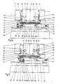
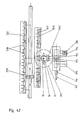
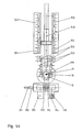
- the interchangeable ring 15 has claws arranged in pairs and pointing upwards at right angles, of which only the claws 80, 81, 82 and 83 can be seen from FIGS. 12 and 13.
- the interchangeable ring 15 On each holder 17, 18, 19 two such claws 80 to 83 can be arranged at a distance from one another and running parallel to one another, which engage in corresponding abutments, of which only the abutments 84 and 85 of the tool carriers 8 and 9 can be seen from the drawing .
- These claws 80 to 83 etc. and the abutments 84 and 85 etc. replace the previous receiving couplings 21 to 31 on the receiving holders 17 to 20.
- the tool carrier 9 In FIG. 13, the tool carrier 9 has already been uncoupled from the energy supply and raised.
- the change ring 15 is ready for pivoting in this position. 13 that the tool carriers 9 and 8 hang on the claws 80, 84 and 83, 85.
- the piston-cylinder unit 73 simultaneously forms a biasing cylinder for the auxiliary slide 2 and tensioning cylinder for the tool carrier 9 or the like which is in the working position.
- an abutment 65 is in turn firmly connected to the substructure 3, to which a stop 66 with roller 67 is assigned, against which the auxiliary slide 62 stops in its end position, that is to say with a horizontal movement in the direction E.
- the mode of operation is like that described in connection with FIGS. 10 and 11.
- the pretensioning of the auxiliary slide 62 and the tensioning of the tool carrier, in each case in the working position, for example the tool carrier 9, are carried out directly on the change ring 15, specifically by the slide unit. The clamping forces therefore do not go through the mounting of the interchangeable ring 15, only the reaction forces.
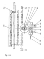
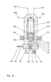
- a piston-cylinder unit 86 is arranged on the slide 2 with a cylinder 87 which is to be acted upon alternately on both sides with pressure medium pressure, in particular hydraulic oil.
- a piston 88 is guided in a longitudinally displaceable and sealing manner, the piston rod 89 of which emerges from the cylinder 87 in a sealed manner and is connected via a joint 90 to a lever 91, which is approximately in its central length range via an axis 92 and a fixed one Bearing 93 is firmly connected to the carriage 2, that is to say can pivot about the axis 92 in the vertical plane.
- the lever 91 has a clamping lug 94 with which it can press against the circumferential surface of the interchangeable ring 15 and thereby clamp the tool carrier, for example 9, which is in the working position.
- the tool carriers 9 and following are again assigned claws 80 and following and abutments 84, preferably in pairs.
- the indexings are also preferably provided in pairs per tool carrier 9.
- Fig. 15 shows the already raised interchangeable ring 15 with the tool carriers 8 and 9 arranged thereon and lever 91 opened by appropriate application of pressure medium for pivoting the interchangeable ring 15.
- the piston 88 is in its other end position compared to the illustration in Fig. 14. Between the auxiliary slide 62 and the roller 67 has in turn a vertical relative movement has taken place in direction A. Otherwise, the horizontal and vertical relative movement between the interchangeable ring 15 and the slide 2 is initiated in the manner already described in connection with FIGS. 10, 11 and 12, 13, respectively.
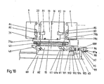
- the abutment 65 is assigned a damping device 96, consists of a piston-cylinder unit 95 and a cylinder 97 is formed with a piston 98 which is longitudinally displaceable and sealingly guided therein.
- a throttle opening 97a is assigned to the cylinder, to which a line (not shown) leading to a tank or the like is connected.
- the throttle 97a can be designed to be controlled or regulated.
- the piston 98 can be returned in its starting position according to FIG. 16 with the application of pressure medium.
- a roller 100 is connected to a piston rod 99, which rests on the end face of the auxiliary slide 62 and can roll in the vertical direction A or T on the corresponding side wall of the auxiliary slide 62, as is shown by a comparison of FIGS. 16 to 18.
- Reference number 101 denotes a further piston-cylinder unit, the cylinder 102 of which is to be acted upon alternately on both sides with pressure medium pressure, in particular hydraulic oil.
- a piston 103 is longitudinally displaceable and sealingly guided in the cylinder 102.
- a piston rod 104 is assigned to the piston 103, which is supported by a roller or the like 105 against the inner wall of the auxiliary slide 62 and prestresses it.
- the clamping claws 106 are designed as two-armed levers which have a clamping lug 107, which each engage in a clamping opening 108 of clamping hooks 109. Two such hooks can be used 109 and in each case one clamping opening 108 can be arranged in parallel and at a distance from one another, which is not apparent from FIGS. 16 to 18.
- the clamping claws 106 are pivotally mounted about horizontal axes 110 and are driven by a spindle nut 111 and a spindle 112 by a motor 113 in both directions for clamping and releasing.
- fig. 16 shows the clamping position of the clamping claws 106 with dash-dotted lines and the open position with solid lines.
- the broken-out part shows the clamping position, left, in Fig. 16.
- the indexings have been given the same reference numerals as in the previously described embodiments.
- Another chip hook has been designated by reference numeral 114.
- the shift in direction D takes place as already described.
- the interchangeable ring 15 is moved in the direction of T, that is to say lowered, the new tool carrier in the working position is fixed, clamped and connected to the energy supply.
- the motor 113 clamps over the clamping claws 107 and the following tool holder in the working position.
- the auxiliary slide 62 When the tool carrier (FIG. 16) is open, the auxiliary slide 62 is thus moved against the stop 100 with the damping device 96. Via the adjustable or controlled or regulated damping, the auxiliary slide 62 with the change ring 15 and the tool carrier 9 or the like is slowly decelerated to a standstill.
- the relative movements of the auxiliary slide 62 and the change ring 15 associated therewith with the drive unit 10 and the DC motor 11 are no longer generated via the slide stroke and a stop and guide curves on the auxiliary slide 62, but are introduced separately via actuators.
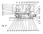
- the horizontal relative movement is initiated via a piston-cylinder unit 115, consisting of a hydraulic cylinder 116 with a piston 117, which is longitudinally displaceable and sealingly guided therein, and a piston rod 118 sealingly led out of the cylinder 116.
- the hydraulic cylinder 116 is mounted on the auxiliary slide 62 so that it can pivot in the vertical plane via a horizontal pivot axis 119.
- the piston rod 118 is arranged so as to be pivotable on the slide 2 via a bearing projection 121 via a further pivot axis 120 running parallel to the pivot axis 119.
- the vertical relative movement of the change ring 15 takes place via a further piston-cylinder unit 122.
- a piston 124 is arranged in a longitudinally displaceable and sealing manner, the piston rod 125 of which seals from the Cylinder 123 is brought out.
- the piston rod 125 are at a distance and by mutually parallel pivot axes 126 and 127 angle levers 128 and 129 pivotally coupled in the vertical plane, the Angle levers 128 and 129 and pivot axes 132 and 133 running parallel to one another are mounted on the carriage 2 so as to be pivotable in the vertical plane.
- the auxiliary carriage 62 is coupled in a manner not shown, so that it can be raised and lowered when the piston 124 and the piston rod 125 are moved.
- the tension of the respective tool carrier in the working position takes place via the change ring 15 via a piston-cylinder unit 134 with cylinder 135 in which a piston 136 is displaceable longitudinally and sealingly, which is coupled to a piston rod 137 which has a pivot axis 138 and an elongated hole a clamping lever 139 is coupled, the clamping lug 140 is able to act against the outer circumference of the change ring 15.
- 19 shows the tensioned position, FIGS. 20 and 21 the relaxed position. This is done by correspondingly alternating pressurization of the piston-cylinder unit 134, in particular by hydraulic oil.
- the mode of operation is such that when the end position is reached by pressurizing the piston-cylinder unit 115, the auxiliary slide 62 is moved relative to the slide 2 in direction D, so that the change ring 15 with the drive unit 10 and the coupled tool holder 9 is stationary.
- the change ring with coupled tool carrier carriers for example with the tool carriers 8 and 9
- the change ring 15 is again ready for rotation about the axis 16. The lowering and resuming, fixing and tensioning of a new tool carrier takes place as described above.
- auxiliary slide 62 takes place via a fixed or damped stop 141 against the auxiliary slide 62 during the preload Via a piston-cylinder unit 142, which consists of a cylinder 143 and a piston 144, which is longitudinally displaceable and sealingly guided therein, with a piston rod 145 sealingly led out of the cylinder 143, which bears against the inner wall of the auxiliary slide 62 under pressure medium pressure, in particular hydraulic pressure.
- a piston-cylinder unit 142 which consists of a cylinder 143 and a piston 144, which is longitudinally displaceable and sealingly guided therein, with a piston rod 145 sealingly led out of the cylinder 143, which bears against the inner wall of the auxiliary slide 62 under pressure medium pressure, in particular hydraulic pressure.
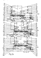
- the vertical relative movement no longer takes place via the change ring 15, but rather by raising or lowering the tool carrier and / or the tool carrier trays, in the embodiment shown in that the tool carrier trays 4, 5 and 6 are driven by a motor, in particular by a spindle drive 146 with motor 147 and gear train 148 in the direction A or T, that is to say in the vertical direction, can be raised and lowered.
- the auxiliary carriage 62 is, for. B. via a piston-cylinder unit 142 with cylinder 143 and longitudinally displaceable and sealing in the cylinder 143 guided piston 144 with sealingly guided out of the cylinder 143 piston rod 145.
- the reference numeral 153 denotes a fixed or damped stop, by means of which the auxiliary slide 62 can be displaced horizontally relative to the slide 2, while the vertical displacement is effected by the controlled motor-driven lowering of the supports 4, 5 and 6.
- 24 shows the position of the interchangeable ring 15 for rotating about the longitudinal axis 16. Indexing and support claws are like the exemplary embodiments described above.
- 25 shows an embodiment with a changed change ring 15, in which some of the indexings 79, 79a, 79f and 79g are provided.
- the claw-shaped shots are as related z. B. with the embodiments 12, 13, 14 and 15, etc. described and shown.
- the relative movements - horizontal and vertical lifting or lowering movement - can also take place in this embodiment provided with additional drive clutches according to each of the principles described in these application documents, i.e. either via coupling linkage, via lifting and lowering shelves or via special actuators, etc.
- the change ring 15 is shown in the rear end position with dash-dotted lines.
- the interchangeable ring is fully drawn in the front end position.
- This embodiment can be a top view of the from FIGS. 12, 13, 14, 15, 16, 17, 18, 19, 20, 21 and 22, 23, 24, of course each with the design changes drawn there.
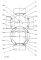
- the change ring 15 is for receiving z. B. four tool carriers 7, 8, 9 and 50 designed. Claws on the interchangeable ring, e.g. B. 80, 81, 82, 83, 164, 164a, 164b, 165 and the counter claws or abutments 84, 84a, 84b, 85, 85a, 85b, 85c, 85d, etc.
- the direction of rotation of the change ring 15 is designated 166.
- the dimension G denotes the stroke of the auxiliary slide 62 relative to the slide 2, while the arrow 166 illustrates the rotary movement about the axis 16.
- the dimension H is the path of the auxiliary slide 62 from the holder or storage position to the working position, while the dimension K represents the stroke of the carriage unit 2, from the holder or holder position to the working position.
- the interchangeable ring 15 is to be equipped with six tool carriers 167, 168, 169, 170, 171, 172.
- the tool carriers not used for machining for example the tool carriers 168 to 172, do not need to be set down in this embodiment, but also remain when the change ring 15 moves with the drive unit 10 and the DC drive 11 and the slide unit 2, on the change ring 15. It is also possible that the three front tool carriers 167, 168 and 172 remain on the change ring 15 when it is moved from the storage or receiving position into the machining position and the three rear tool carriers 169, 170, 171 are placed on the associated tool holder trays 4, 5 and 6.
- more than four tool carriers namely six tool carriers 167, 168, 169, 170, 171 and 172, are also assigned to the change ring 15.
- the pivotability of the tool carrier trays is indicated by the double arrows 173 and 174, which can be pivoted about the pivot points 175 and 176.
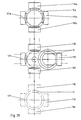
- FIG. 29 shows an interchangeable ring 15 which has four tool carriers 177, 178, 179 and 180, the interchangeable ring 15 in question, with its four tool carriers 177, 178, 179 and 180, being interchangeable as a complete structural unit by means of a lifting device (not shown) second interchangeable ring 15a with a second set of tool carriers 177a, 178a, 179a and 180a.
- a lifting device not shown
- second interchangeable ring 15a with a second set of tool carriers 177a, 178a, 179a and 180a Such complete interchangeable rings 15 with tool carriers arranged thereon can be kept ready in a magazine. However, it is also possible to change the change ring 15 mechanically, for example via roller conveyors or the like.
- 29 shows the method of changing ring 15 in the manner described from a depositing or receiving station or changing station into a processing position, which was illustrated in the middle representation with solid lines.
- more than four heads for example similar to the above-described embodiments, six or more tool carriers are to be arranged on the interchangeable ring.
- a magazine 191 which is motor-driven and in which a plurality of tool carriers are arranged, is assigned to the change ring 15, which is only indicated schematically.
- This variant works with a total of ten tool carriers 181 to 190, the tool carrier 181 being in the machining position on the change ring 15.
- the magazine 181 has a roller conveyor for transporting the individual tool carriers 181 to 190.
- the interchangeable ring 15 passes under the respective tool carrier to be received, for example the tool carrier 182 and hangs it on via a vertical lifting movement, or the part of the roller conveyor in question is raised or lowered in order to hang the tool carrier 182 or others on the receiving couplings of the interchangeable ring 15 . Then there is a rotary movement of the change ring 15 in the manner described about the axis of rotation 16 in order to bring the new tool carrier, for example 182, into the machining position.
- a workpiece 193 is arranged on a pallet 192. With 194 and 195 are designated pallet parking spaces.
- 196 denotes a slide drive and 197 an energy supply for the slide drive.
- Another workpiece 198 to be processed is arranged on the pallet 192.
- 199 are the interference edges of the tools arranged on the change ring 15.
- a single magazine 200 is assigned to the change ring 15, in which ten tool carriers are to be arranged.
- the tool carrier 201 is currently in the machining position on the change ring 15, while the other tool carriers 202 to 210 are in the single magazine.
- a single magazine 241, mounted lengthways, is provided, with eight tool carriers in the magazine and twelve tool carriers in total.
- the tool carriers are designated by the reference numerals 242 to 253, the tool carrier 242 being in the machining position.
- a round magazine 273 is provided for random access to six tool carriers or more 274 to 279, an indexing table 280 in the embodiment shown being switchable by 6 x 60 ° by motor.
- Reference numeral 281 denotes a converter for moving the tool carriers 274 to 279 from the round magazine 273 to the change ring 15 and for their return transport from the change ring 15 to the round magazine 273.
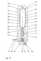
- an oval magazine 282 is assigned to the change ring 15 for random access to tool carriers.
- a converter 281 transports the respectively selected tool carrier from the oval magazine 282 to the change ring 15 and vice versa from the change ring 15 to the oval magazine 282.
- the oval magazine 282 is designed to receive 16 tool carriers.
- the tool carrier 283 is in the machining position, while the tool carriers 285, 286, 287, 288, 289, 290, 291, 292, 293, 294, 295, 296, 297, 298, 299, 299a are arranged in the oval magazine 282.
- the oval magazine 282 can be equipped with roller conveyors, chains or the like, which are each driven by a motor.
- the interchangeable ring 15 is assigned a transversely mounted magazine 300, which can also have motor-driven roller conveyors, chains or the like.
- the tool carrier 301 is in the processing position, while the tool carriers can be transported from the transversely mounted magazine 300 to the change ring 15 and vice versa from the change ring 15 to the transversely installed magazine 300 via a converter 281.
- Other tool carriers are identified by reference numerals 301 to 319.
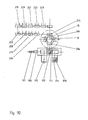
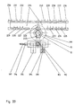
- FIG. 39 shows a side view of the design of the longitudinally mounted magazine 282, according to FIG. 37, which has a drive station 320, an extension 321 and a deflection station 322.
- the drive station 320 and the deflection station 322 are arranged above the floor via a base frame 323 and 324, respectively, during the extension 321 at least one support 325 is assigned.
- the tool carriers 283 to 299a are each arranged on a transport trolley, of which only the transport trolleys 326 and 327 have been shown schematically in FIG. 39. Without the extension, the magazine 300 z. B. accommodate eight tool carriers.
- the reference numeral 328 denotes a motor for the converter 281, which rests on the floor via a base frame 329.
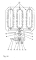
- FIG. 40 shows a double magazine 330 for thirty-two tool carriers with two oval circulation magazines 331 and 332 and a movable converter 333 for motor-driven transport of tool carriers between the two oval circulation magazines 331 and 332 and the change ring 15.
- Numeral 334 illustrates a tool carrier in the machining position.
- B. 2 x 16 32 tool carriers may be provided, which are not in detail were specified.
- a motor-driven converter 335 is arranged between the change ring 15 and a triple magazine 336 for forty-eight tool carriers.
- FIG. 42 illustrates a single-sided high rack 337, in which numerous tool carriers 338 are arranged, which are arranged via a rack conveyor 339, which can be moved by motor in the longitudinal direction of the high rack 337.
- Reference number 340 denotes an intermediate store for tool carriers, of which only tool carrier 341 has been designated.
- the tool carrier 342 is currently in the machining position.
- a shelf conveyor 348 is also provided, with a high-bay warehouse 349 and 350 being arranged on each side of the shelf conveyor 348, in each of which a plurality of tool carriers 351 and 352 are arranged, which are arranged via an intermediate storage 353 and a swivel and sliding station 354 transport the tool carriers from the high-bay stores 349, 350 to the change ring 15 and vice versa from the change ring 15 to the high-bay stores.
- all racking conveyors and magazines, including high-bay storage systems can be operated by motor or with motorized racking conveyors.
- the assignment of the tools and the workpieces to one another can be computer-controlled, in particular by numerical controls, in particular also when several processing machines according to the invention are arranged in a chain-like manner in transfer lines or the like and the assignment of tools and workpieces to the individual processing machines numerically controlled.
- a high rack system 355 is provided, with a rack conveyor 356 and tool changing stations 357, 358.
- FIG. 46 there is a high rack 359 and a rack conveyor 360 for the various tool carriers, of which only the tool carrier 361 is designated.
- the reference symbols 363, 364, 365 and 366 denote pallet storage spaces which can be loaded optionally.
- FIG. 47 shows a magazine 367 for numerous tool carriers with shunting tracks 368 and 369 as well as 368a and 369a and additional parking spaces 370, 371 and 372 for special tool carriers 373, 374 and 375, which are either repeat tool carriers (e.g. milling heads ) or z. B. fine turrets, the circulating lubricating oil can be cooled and heated in these additional parking spaces.
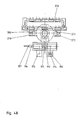
- the embodiment according to FIG. 48 shows a transverse magazine 376 for the arrangement of numerous tool carriers 378 with two additional parking spaces 377 and 378 for storing tool carriers 379 and 380.
- the transverse magazine 376 is arranged symmetrically.
- the tensioning in the illustrated embodiment can also take place via the parts 86 to 94 by means of the clamping claw 91.
- hydraulic piston-cylinder units or pneumatic piston-cylinder units or end stops or spring elements are shown in the embodiments, there is of course nothing standing in the way of exchanging one element for the other, for example a pneumatic tension and / or suspension and / or to replace an end stop with such a hydraulic type.
- hydraulic and / or pneumatic piston-cylinder units for tensioning and / or fixing and / or as end stops can of course also be replaced by mechanical elements, in particular by motor-driven threaded spindles and nuts or by one or more springs of any type, without the Leave the scope of the invention.
Landscapes
- Engineering & Computer Science (AREA)
- Mechanical Engineering (AREA)
- Soil Working Implements (AREA)
- Electrical Discharge Machining, Electrochemical Machining, And Combined Machining (AREA)
- Feeding Of Workpieces (AREA)
- Automatic Tool Replacement In Machine Tools (AREA)
Priority Applications (5)
| Application Number | Priority Date | Filing Date | Title |
|---|---|---|---|
| DE8686113064T DE3673167D1 (de) | 1986-09-23 | 1986-09-23 | Bearbeitungsmaschine. |
| EP86113064A EP0261261B1 (fr) | 1986-09-23 | 1986-09-23 | Machine-outil |
| AT86113064T ATE55079T1 (de) | 1986-09-23 | 1986-09-23 | Bearbeitungsmaschine. |
| ES8700820A ES2004392A6 (es) | 1986-09-23 | 1987-03-24 | Maquina de mecanizacion |
| BR8704220A BR8704220A (pt) | 1986-09-23 | 1987-08-14 | Maquina de trabalho |
Applications Claiming Priority (1)
| Application Number | Priority Date | Filing Date | Title |
|---|---|---|---|
| EP86113064A EP0261261B1 (fr) | 1986-09-23 | 1986-09-23 | Machine-outil |
Publications (2)
| Publication Number | Publication Date |
|---|---|
| EP0261261A1 true EP0261261A1 (fr) | 1988-03-30 |
| EP0261261B1 EP0261261B1 (fr) | 1990-08-01 |
Family
ID=8195437
Family Applications (1)
| Application Number | Title | Priority Date | Filing Date |
|---|---|---|---|
| EP86113064A Expired - Lifetime EP0261261B1 (fr) | 1986-09-23 | 1986-09-23 | Machine-outil |
Country Status (5)
| Country | Link |
|---|---|
| EP (1) | EP0261261B1 (fr) |
| AT (1) | ATE55079T1 (fr) |
| BR (1) | BR8704220A (fr) |
| DE (1) | DE3673167D1 (fr) |
| ES (1) | ES2004392A6 (fr) |
Cited By (7)
| Publication number | Priority date | Publication date | Assignee | Title |
|---|---|---|---|---|
| FR2665856A1 (fr) * | 1990-08-20 | 1992-02-21 | Monarch Machine Tool Cy | Machine-outil a remplacement automatique des tetes revolver, et mecanisme associe d'indexage des tetes revolver. |
| EP0634237A1 (fr) * | 1990-06-04 | 1995-01-18 | Amada Company Limited | Poinçonneuse à tourelles révolver |
| EP0796701A1 (fr) * | 1996-03-21 | 1997-09-24 | Handtmann A-Punkt Automation GmbH | Etau |
| WO1998058764A1 (fr) * | 1997-06-21 | 1998-12-30 | Sigmund Kumeth | Dispositif de preparation et/ou de montage |
| DE19749633B4 (de) * | 1997-11-11 | 2005-06-09 | Feintool International Holding | Fertigungs- und/oder Montagevorrichtung |
| CN108907771A (zh) * | 2018-07-03 | 2018-11-30 | 芜湖恒跃智能装备有限公司 | 一种工装夹具的快速切换机构 |
| CN108907790A (zh) * | 2018-07-03 | 2018-11-30 | 芜湖恒跃智能装备有限公司 | 一种可定位夹具 |
Families Citing this family (1)
| Publication number | Priority date | Publication date | Assignee | Title |
|---|---|---|---|---|
| CN109571102B (zh) * | 2018-10-24 | 2021-02-02 | 东莞市友鸿机电设备有限公司 | 一种可快速换刀金属加工机床 |
Citations (29)
| Publication number | Priority date | Publication date | Assignee | Title |
|---|---|---|---|---|
| US3286595A (en) * | 1964-09-26 | 1966-11-22 | Wollenhaupt Jakob | Machine tool |
| DE1502010A1 (de) | 1964-09-26 | 1970-02-26 | Jakob Wollenhaupt | Werkzeugmaschine mit automatischem Werkzeugwechsel |
| DE2055562A1 (de) * | 1969-11-13 | 1971-07-29 | Etablissement Allemann, Prazisions maschinenbau, Schaanwald (Liechtenstein) | Werkzeugmaschine |
| DE2026221A1 (de) | 1970-05-29 | 1971-12-09 | Bw Weber Verwaltungs Gmbh | Werkzeugmaschine mit einer Bearbeitungs einheit fur auswechselbare Mehrspindelkopfe |
| DE2026336A1 (de) | 1970-05-29 | 1971-12-09 | Maschf Augsburg Nuernberg Ag | Werkzeugmaschine mit mehreren, gleichzeitig arbeitenden Werkzeugen |
| DE2036757A1 (de) | 1970-07-24 | 1972-01-27 | Maschf Augsburg Nuernberg Ag | Emspindel-Werkzeugmaschine |
| DE2103741A1 (de) | 1971-01-27 | 1972-08-10 | Buchmeier H | Ferngesteuerter Bohrrevolverkopf fur Werkzeugmaschinen |
| DE2352879A1 (de) | 1973-10-22 | 1975-04-30 | Otto Oeckl | Bohranlage |
| US4038739A (en) | 1974-12-04 | 1977-08-02 | The Mollart Engineering Company, Limited | Machine tools having interchangeable tool carrying units |
| DE2617608A1 (de) | 1976-04-22 | 1977-11-03 | Jakob Wollenhaupt | Werkzeugmaschine mit einer automatischen werkzeugwechseleinrichtung |
| DE2630047A1 (de) * | 1976-07-03 | 1978-01-12 | Heller Geb Gmbh Maschf | Fraeswerkzeug zur bearbeitung von kurbelwellen und kurbelwellenfraesmaschine zur verwendung dieses fraeswerkzeuges |
| DE2753801A1 (de) | 1976-12-02 | 1978-06-08 | Bendix Machine Tool | Verfahren und vorrichtung zum auswechseln von werkzeugkoepfen an werkzeugmaschinen |
| US4110898A (en) | 1976-03-02 | 1978-09-05 | Kanzaki Kokyukoki Mfg. Co., Ltd. | Machine tool |
| BE874891A (fr) * | 1978-11-28 | 1979-07-16 | Honda Motor Co Ltd | Machine-outil a tetes multibroches interchangeables |
| US4216572A (en) | 1978-12-07 | 1980-08-12 | Honda Giken Kogyo Kabushiki Kaisha | Replaceable gang head machine tool |
| JPS55112753A (en) | 1979-02-13 | 1980-08-30 | Toyoda Mach Works Ltd | Numerically controlled machine tool with pallet replacing function |
| DE2934395A1 (de) | 1979-08-24 | 1981-03-12 | Maschinenfabrik Diedesheim GmbH, 6950 Mosbach | Verfahren und vorrichtung zum betrieb einer mit einer mehrzahl unterschiedlicher werkzeuge bestueckbaren bearbeitungsmaschine fuer werkstuecke. |
| GB2056350A (en) * | 1979-08-24 | 1981-03-18 | Diedesheim Gmbh Maschf | Replaceable tool turret |
| DE2950934A1 (de) | 1979-12-18 | 1981-06-25 | Maschinenfabrik Diedesheim GmbH, 6950 Mosbach | Verfahren zum betrieb einer mit einer mehrzahl unterschiedlicher werkzeuge bestueckbaren bearbeitungsmaschine fuer werkstuecke |
| GB2077150A (en) | 1980-05-14 | 1981-12-16 | Translift Gmbh | An arrangement for changing tools |
| US4318665A (en) | 1980-02-07 | 1982-03-09 | Litton Industrial Products, Inc. | Machining center with tool shuttle |
| DE3239482A1 (de) | 1981-10-23 | 1983-05-11 | Honda Giken Kogyo K.K., Tokyo | Werkzeugmaschine mit auswechselbarem werkzeugkopf |
| DE3146429A1 (de) | 1981-11-24 | 1983-06-01 | Bernhard Steinel Werkzeugmaschinenfabrik GmbH u. Co, 7730 Villingen-Schwenningen | "bearbeitungszentrum" |
| US4428256A (en) | 1980-07-03 | 1984-01-31 | Honda Giken Kogyo Kabushiki Kaisha | Geneva gear apparatus for driving an index table |
| EP0133456A2 (fr) * | 1983-08-04 | 1985-02-27 | Wanderer Maschinen Gesellschaft mbH | Dispositif pour la fabrication flexible de pièces à usiner |
| DE3329539A1 (de) | 1983-08-16 | 1985-03-07 | Hüller Hille GmbH, 7140 Ludwigsburg | Verfahren zum wechseln eines werkzeugtraegers an einer bearbeitungseinheit zum bearbeiten von werkstuecken und vorrichtung zum durchfuehren des verfahrens |
| GB2151954A (en) * | 1983-11-29 | 1985-07-31 | Honda Motor Co Ltd | Replaceable gang head machine tool |
| FR2568802A1 (fr) * | 1984-08-07 | 1986-02-14 | Renault | Tete multibroches pour machine-outil, notamment pour ensemble d'usinage a tetes interchangeables |
| EP0193465A1 (fr) * | 1985-02-28 | 1986-09-03 | Renault Automation | Unité trois axes à commande numérique, notamment pour machine transfert et atelier flexible |
-
1986
- 1986-09-23 AT AT86113064T patent/ATE55079T1/de not_active IP Right Cessation
- 1986-09-23 EP EP86113064A patent/EP0261261B1/fr not_active Expired - Lifetime
- 1986-09-23 DE DE8686113064T patent/DE3673167D1/de not_active Expired - Lifetime
-
1987
- 1987-03-24 ES ES8700820A patent/ES2004392A6/es not_active Expired
- 1987-08-14 BR BR8704220A patent/BR8704220A/pt not_active IP Right Cessation
Patent Citations (31)
| Publication number | Priority date | Publication date | Assignee | Title |
|---|---|---|---|---|
| US3286595A (en) * | 1964-09-26 | 1966-11-22 | Wollenhaupt Jakob | Machine tool |
| DE1502010A1 (de) | 1964-09-26 | 1970-02-26 | Jakob Wollenhaupt | Werkzeugmaschine mit automatischem Werkzeugwechsel |
| DE2055562A1 (de) * | 1969-11-13 | 1971-07-29 | Etablissement Allemann, Prazisions maschinenbau, Schaanwald (Liechtenstein) | Werkzeugmaschine |
| DE2026221A1 (de) | 1970-05-29 | 1971-12-09 | Bw Weber Verwaltungs Gmbh | Werkzeugmaschine mit einer Bearbeitungs einheit fur auswechselbare Mehrspindelkopfe |
| DE2026336A1 (de) | 1970-05-29 | 1971-12-09 | Maschf Augsburg Nuernberg Ag | Werkzeugmaschine mit mehreren, gleichzeitig arbeitenden Werkzeugen |
| DE2036757A1 (de) | 1970-07-24 | 1972-01-27 | Maschf Augsburg Nuernberg Ag | Emspindel-Werkzeugmaschine |
| DE2103741A1 (de) | 1971-01-27 | 1972-08-10 | Buchmeier H | Ferngesteuerter Bohrrevolverkopf fur Werkzeugmaschinen |
| DE2352879A1 (de) | 1973-10-22 | 1975-04-30 | Otto Oeckl | Bohranlage |
| US4038739A (en) | 1974-12-04 | 1977-08-02 | The Mollart Engineering Company, Limited | Machine tools having interchangeable tool carrying units |
| US4110898A (en) | 1976-03-02 | 1978-09-05 | Kanzaki Kokyukoki Mfg. Co., Ltd. | Machine tool |
| DE2617608A1 (de) | 1976-04-22 | 1977-11-03 | Jakob Wollenhaupt | Werkzeugmaschine mit einer automatischen werkzeugwechseleinrichtung |
| DE2630047A1 (de) * | 1976-07-03 | 1978-01-12 | Heller Geb Gmbh Maschf | Fraeswerkzeug zur bearbeitung von kurbelwellen und kurbelwellenfraesmaschine zur verwendung dieses fraeswerkzeuges |
| DE2753801A1 (de) | 1976-12-02 | 1978-06-08 | Bendix Machine Tool | Verfahren und vorrichtung zum auswechseln von werkzeugkoepfen an werkzeugmaschinen |
| US4354306A (en) | 1978-11-28 | 1982-10-19 | Honda Giken Kogyo Kabushiki Kaisha | Machine tool having replaceable gang heads |
| BE874891A (fr) * | 1978-11-28 | 1979-07-16 | Honda Motor Co Ltd | Machine-outil a tetes multibroches interchangeables |
| US4216572A (en) | 1978-12-07 | 1980-08-12 | Honda Giken Kogyo Kabushiki Kaisha | Replaceable gang head machine tool |
| JPS55112753A (en) | 1979-02-13 | 1980-08-30 | Toyoda Mach Works Ltd | Numerically controlled machine tool with pallet replacing function |
| DE2934395A1 (de) | 1979-08-24 | 1981-03-12 | Maschinenfabrik Diedesheim GmbH, 6950 Mosbach | Verfahren und vorrichtung zum betrieb einer mit einer mehrzahl unterschiedlicher werkzeuge bestueckbaren bearbeitungsmaschine fuer werkstuecke. |
| GB2056350A (en) * | 1979-08-24 | 1981-03-18 | Diedesheim Gmbh Maschf | Replaceable tool turret |
| DE2950934A1 (de) | 1979-12-18 | 1981-06-25 | Maschinenfabrik Diedesheim GmbH, 6950 Mosbach | Verfahren zum betrieb einer mit einer mehrzahl unterschiedlicher werkzeuge bestueckbaren bearbeitungsmaschine fuer werkstuecke |
| US4318665A (en) | 1980-02-07 | 1982-03-09 | Litton Industrial Products, Inc. | Machining center with tool shuttle |
| GB2077150A (en) | 1980-05-14 | 1981-12-16 | Translift Gmbh | An arrangement for changing tools |
| US4428256A (en) | 1980-07-03 | 1984-01-31 | Honda Giken Kogyo Kabushiki Kaisha | Geneva gear apparatus for driving an index table |
| DE3239482A1 (de) | 1981-10-23 | 1983-05-11 | Honda Giken Kogyo K.K., Tokyo | Werkzeugmaschine mit auswechselbarem werkzeugkopf |
| DE3146429A1 (de) | 1981-11-24 | 1983-06-01 | Bernhard Steinel Werkzeugmaschinenfabrik GmbH u. Co, 7730 Villingen-Schwenningen | "bearbeitungszentrum" |
| EP0133456A2 (fr) * | 1983-08-04 | 1985-02-27 | Wanderer Maschinen Gesellschaft mbH | Dispositif pour la fabrication flexible de pièces à usiner |
| DE3329539A1 (de) | 1983-08-16 | 1985-03-07 | Hüller Hille GmbH, 7140 Ludwigsburg | Verfahren zum wechseln eines werkzeugtraegers an einer bearbeitungseinheit zum bearbeiten von werkstuecken und vorrichtung zum durchfuehren des verfahrens |
| EP0137117A2 (fr) | 1983-08-16 | 1985-04-17 | Hüller Hille GmbH | Dispositif changeur d'outils comprenant un appareil pour le transfert des têtes d'outils |
| GB2151954A (en) * | 1983-11-29 | 1985-07-31 | Honda Motor Co Ltd | Replaceable gang head machine tool |
| FR2568802A1 (fr) * | 1984-08-07 | 1986-02-14 | Renault | Tete multibroches pour machine-outil, notamment pour ensemble d'usinage a tetes interchangeables |
| EP0193465A1 (fr) * | 1985-02-28 | 1986-09-03 | Renault Automation | Unité trois axes à commande numérique, notamment pour machine transfert et atelier flexible |
Non-Patent Citations (7)
| Title |
|---|
| Machines Production, 7 November 1985, Seiten 27, 31, 33-38; Sofetec, Boulogne, FRA, "Formage: enfin la flexibilite", Seiten 34, 35; Figuren 9-11. * |
| PATENT ABSTRACTS OF JAPAN, Band 7, Nr. 92 (M-208)(1237), 16 April 1983; & JP-A-58 015 651 (NIIGATA TEKKOSHO K.K.) 29-01-1983, Figur 1. * |
| PATENT ABSTRACTS OF JAPAN, Seite 4483M77; & JP-A-52 071 776 (TOSHIBA KIKAI K.K.) 15-06-1977, Figuren 1,2. * |
| Werkstatt und Betrieb, Jahrgang 117, Nr. 8, August 1984, Seiten 471-476; Muenchen, DE, H. HAMMER: "Konzeptionen flexibler Fertigungssysteme fuer den Fahrzeugbau", Seiten 471-474; Figuren 2,4,7. * |
| Werkstatt und Betrieb, Jahrgang 117, Nr. 8, August 1984, Seiten A40, A41; MAUSER-TECHNOLOGIE-INFORMATION: "Flexible Fertigungszelle MAUSER TMC 1000 mit Bohrkopfwechsler fuer Werkstuecke bis 1000x1000x1000 mm", Seite A 41. * |
| Werkstatt und Betrieb, Jahrgang 119, Nr. 6, Juni 1986, Seiten 437-440; Carl Hanser Verlag, Muenchen, DE, B. GRUEN et al.: "Flexibles Fertigungssystem zur Komplettbearbeitung von LKW-Getriebegehaeusen", Seiten 438, 439; Figur 2. * |
| Werkstatttechnik, Zeitschrift fuer Industrielle Fertigung; Jahrgang 74, Nr. 11, November 1984, Seiten 633, 634; Springer Verlag, Berlin, DE, "Baukasten fuer flexible Systeme um Bohrkopfwechselsystem ergaenzt", Seite 634; Figuren 1,2. * |
Cited By (7)
| Publication number | Priority date | Publication date | Assignee | Title |
|---|---|---|---|---|
| EP0634237A1 (fr) * | 1990-06-04 | 1995-01-18 | Amada Company Limited | Poinçonneuse à tourelles révolver |
| FR2665856A1 (fr) * | 1990-08-20 | 1992-02-21 | Monarch Machine Tool Cy | Machine-outil a remplacement automatique des tetes revolver, et mecanisme associe d'indexage des tetes revolver. |
| EP0796701A1 (fr) * | 1996-03-21 | 1997-09-24 | Handtmann A-Punkt Automation GmbH | Etau |
| WO1998058764A1 (fr) * | 1997-06-21 | 1998-12-30 | Sigmund Kumeth | Dispositif de preparation et/ou de montage |
| DE19749633B4 (de) * | 1997-11-11 | 2005-06-09 | Feintool International Holding | Fertigungs- und/oder Montagevorrichtung |
| CN108907771A (zh) * | 2018-07-03 | 2018-11-30 | 芜湖恒跃智能装备有限公司 | 一种工装夹具的快速切换机构 |
| CN108907790A (zh) * | 2018-07-03 | 2018-11-30 | 芜湖恒跃智能装备有限公司 | 一种可定位夹具 |
Also Published As
| Publication number | Publication date |
|---|---|
| ATE55079T1 (de) | 1990-08-15 |
| DE3673167D1 (de) | 1990-09-06 |
| EP0261261B1 (fr) | 1990-08-01 |
| ES2004392A6 (es) | 1989-01-01 |
| BR8704220A (pt) | 1988-04-26 |
Similar Documents
| Publication | Publication Date | Title |
|---|---|---|
| DE69907283T2 (de) | Maschine zum bohren von öllöchern in kurbelwellen und dessen methode | |
| EP2263827B1 (fr) | Appareil pour usiner des pièces | |
| EP3529000B1 (fr) | Dispositif de transport, procédé et produit-programme informatique destiné à charger et décharger au moins une machine d'usinage de matériau | |
| DE2739534C2 (de) | Werkzeugwechselvorrichtung | |
| DE102019111873A1 (de) | Werkzeugmaschine mit Portal | |
| EP3535092B1 (fr) | Machine de pierrage avec une pluralité de postes de travail | |
| DE3331293C2 (fr) | ||
| DD244933C4 (de) | Werkzeugmaschine | |
| DE3134833C2 (de) | Palettenwechseleinrichtung bei einer numerisch gesteuerten Werkzeugmaschine | |
| DE69201293T2 (de) | Vertikale Drehbank. | |
| DE202014009762U1 (de) | Werkzeugwechselvorrichtung zur Verwendung in einem Bearbeitungszentrum und Bearbeitungszentrum zur maschinellen Bearbeitung eines Werkstücks | |
| EP0261261B1 (fr) | Machine-outil | |
| EP2762253B1 (fr) | Machine-outil destinée au traitement de pièces à usiner | |
| EP0273932B1 (fr) | Dispositif de changement d'outils pour machines-outils | |
| DE3914970A1 (de) | Anlage zum schweissen von kraftfahrzeugkarosserien in einer einzigen bearbeitungsstation | |
| EP0137117B1 (fr) | Dispositif changeur d'outils comprenant un appareil pour le transfert des têtes d'outils | |
| EP1768817A2 (fr) | Machine transfert flexible avec des porte-pieces mobiles | |
| DE19652460C1 (de) | Werkzeugmaschine mit mehreren Spindeln | |
| DE3001396C2 (fr) | ||
| DE3410656A1 (de) | Werkzeugmaschine mit einem in mehreren achsen beweglichen spindelstock | |
| DE3734688C1 (en) | Workpiece handling device on a lathe | |
| DE4022706C2 (de) | Drehmaschine | |
| DE1804630A1 (de) | Werkzeugmagazin fuer Drehmaschinen | |
| DE10354706B3 (de) | Werkzeugmaschine mit Transportvorrichtung | |
| DE3918901C2 (fr) |
Legal Events
| Date | Code | Title | Description |
|---|---|---|---|
| PUAI | Public reference made under article 153(3) epc to a published international application that has entered the european phase |
Free format text: ORIGINAL CODE: 0009012 |
|
| 17P | Request for examination filed |
Effective date: 19861031 |
|
| AK | Designated contracting states |
Kind code of ref document: A1 Designated state(s): AT BE CH DE FR GB IT LI LU NL SE |
|
| 17Q | First examination report despatched |
Effective date: 19880914 |
|
| GRAA | (expected) grant |
Free format text: ORIGINAL CODE: 0009210 |
|
| ITF | It: translation for a ep patent filed | ||
| AK | Designated contracting states |
Kind code of ref document: B1 Designated state(s): AT BE CH DE FR GB IT LI LU NL SE |
|
| REF | Corresponds to: |
Ref document number: 55079 Country of ref document: AT Date of ref document: 19900815 Kind code of ref document: T |
|
| REF | Corresponds to: |
Ref document number: 3673167 Country of ref document: DE Date of ref document: 19900906 |
|
| ET | Fr: translation filed | ||
| GBT | Gb: translation of ep patent filed (gb section 77(6)(a)/1977) | ||
| PLBE | No opposition filed within time limit |
Free format text: ORIGINAL CODE: 0009261 |
|
| STAA | Information on the status of an ep patent application or granted ep patent |
Free format text: STATUS: NO OPPOSITION FILED WITHIN TIME LIMIT |
|
| 26N | No opposition filed | ||
| PGFP | Annual fee paid to national office [announced via postgrant information from national office to epo] |
Ref country code: LU Payment date: 19910927 Year of fee payment: 6 |
|
| ITTA | It: last paid annual fee | ||
| EPTA | Lu: last paid annual fee | ||
| PG25 | Lapsed in a contracting state [announced via postgrant information from national office to epo] |
Ref country code: LU Free format text: LAPSE BECAUSE OF NON-PAYMENT OF DUE FEES Effective date: 19920923 |
|
| EAL | Se: european patent in force in sweden |
Ref document number: 86113064.9 |
|
| PGFP | Annual fee paid to national office [announced via postgrant information from national office to epo] |
Ref country code: GB Payment date: 19990813 Year of fee payment: 14 |
|
| PGFP | Annual fee paid to national office [announced via postgrant information from national office to epo] |
Ref country code: CH Payment date: 19990816 Year of fee payment: 14 |
|
| PGFP | Annual fee paid to national office [announced via postgrant information from national office to epo] |
Ref country code: FR Payment date: 19990817 Year of fee payment: 14 |
|
| PGFP | Annual fee paid to national office [announced via postgrant information from national office to epo] |
Ref country code: NL Payment date: 19990819 Year of fee payment: 14 |
|
| PGFP | Annual fee paid to national office [announced via postgrant information from national office to epo] |
Ref country code: DE Payment date: 19990820 Year of fee payment: 14 |
|
| PGFP | Annual fee paid to national office [announced via postgrant information from national office to epo] |
Ref country code: SE Payment date: 19990823 Year of fee payment: 14 |
|
| PGFP | Annual fee paid to national office [announced via postgrant information from national office to epo] |
Ref country code: AT Payment date: 19990824 Year of fee payment: 14 |
|
| PGFP | Annual fee paid to national office [announced via postgrant information from national office to epo] |
Ref country code: BE Payment date: 19990827 Year of fee payment: 14 |
|
| PG25 | Lapsed in a contracting state [announced via postgrant information from national office to epo] |
Ref country code: GB Free format text: LAPSE BECAUSE OF NON-PAYMENT OF DUE FEES Effective date: 20000923 Ref country code: AT Free format text: LAPSE BECAUSE OF NON-PAYMENT OF DUE FEES Effective date: 20000923 |
|
| PG25 | Lapsed in a contracting state [announced via postgrant information from national office to epo] |
Ref country code: SE Free format text: THE PATENT HAS BEEN ANNULLED BY A DECISION OF A NATIONAL AUTHORITY Effective date: 20000929 |
|
| PG25 | Lapsed in a contracting state [announced via postgrant information from national office to epo] |
Ref country code: LI Free format text: LAPSE BECAUSE OF NON-PAYMENT OF DUE FEES Effective date: 20000930 Ref country code: CH Free format text: LAPSE BECAUSE OF NON-PAYMENT OF DUE FEES Effective date: 20000930 Ref country code: BE Free format text: LAPSE BECAUSE OF NON-PAYMENT OF DUE FEES Effective date: 20000930 |
|
| BERE | Be: lapsed |
Owner name: HULLER HILLE G.M.B.H. Effective date: 20000930 |
|
| PG25 | Lapsed in a contracting state [announced via postgrant information from national office to epo] |
Ref country code: NL Free format text: LAPSE BECAUSE OF NON-PAYMENT OF DUE FEES Effective date: 20010401 |
|
| REG | Reference to a national code |
Ref country code: CH Ref legal event code: PL |
|
| GBPC | Gb: european patent ceased through non-payment of renewal fee |
Effective date: 20000923 |
|
| EUG | Se: european patent has lapsed |
Ref document number: 86113064.9 |
|
| PG25 | Lapsed in a contracting state [announced via postgrant information from national office to epo] |
Ref country code: FR Free format text: LAPSE BECAUSE OF NON-PAYMENT OF DUE FEES Effective date: 20010531 |
|
| NLV4 | Nl: lapsed or anulled due to non-payment of the annual fee |
Effective date: 20010401 |
|
| PG25 | Lapsed in a contracting state [announced via postgrant information from national office to epo] |
Ref country code: DE Free format text: LAPSE BECAUSE OF NON-PAYMENT OF DUE FEES Effective date: 20010601 |
|
| REG | Reference to a national code |
Ref country code: FR Ref legal event code: ST |
|
| PG25 | Lapsed in a contracting state [announced via postgrant information from national office to epo] |
Ref country code: IT Free format text: LAPSE BECAUSE OF NON-PAYMENT OF DUE FEES;WARNING: LAPSES OF ITALIAN PATENTS WITH EFFECTIVE DATE BEFORE 2007 MAY HAVE OCCURRED AT ANY TIME BEFORE 2007. THE CORRECT EFFECTIVE DATE MAY BE DIFFERENT FROM THE ONE RECORDED. Effective date: 20050923 |