EP0261277A2 - Support, notamment vertical pour calendrier ou autres choses semblables - Google Patents
Support, notamment vertical pour calendrier ou autres choses semblables Download PDFInfo
- Publication number
- EP0261277A2 EP0261277A2 EP86115603A EP86115603A EP0261277A2 EP 0261277 A2 EP0261277 A2 EP 0261277A2 EP 86115603 A EP86115603 A EP 86115603A EP 86115603 A EP86115603 A EP 86115603A EP 0261277 A2 EP0261277 A2 EP 0261277A2
- Authority
- EP
- European Patent Office
- Prior art keywords
- holder according
- rear wall
- top wall
- tab
- holder
- Prior art date
- Legal status (The legal status is an assumption and is not a legal conclusion. Google has not performed a legal analysis and makes no representation as to the accuracy of the status listed.)
- Withdrawn
Links
- 238000004049 embossing Methods 0.000 claims description 6
- 238000003780 insertion Methods 0.000 claims description 5
- 230000037431 insertion Effects 0.000 claims description 5
- 229920003023 plastic Polymers 0.000 claims description 2
- 238000013459 approach Methods 0.000 claims 1
- 230000001427 coherent effect Effects 0.000 claims 1
- 238000004519 manufacturing process Methods 0.000 abstract description 5
- 238000000034 method Methods 0.000 abstract 1
- 239000002991 molded plastic Substances 0.000 abstract 1
- 241000047428 Halter Species 0.000 description 6
- 239000000463 material Substances 0.000 description 3
- 238000005452 bending Methods 0.000 description 1
- 230000015572 biosynthetic process Effects 0.000 description 1
- 238000001746 injection moulding Methods 0.000 description 1
- 239000004033 plastic Substances 0.000 description 1
- 239000002985 plastic film Substances 0.000 description 1
- 229920006255 plastic film Polymers 0.000 description 1
- 230000001737 promoting effect Effects 0.000 description 1
- 238000004080 punching Methods 0.000 description 1
- 239000000725 suspension Substances 0.000 description 1
- 210000002105 tongue Anatomy 0.000 description 1
- 230000007704 transition Effects 0.000 description 1
- 230000003442 weekly effect Effects 0.000 description 1
Images




Classifications
-
- B—PERFORMING OPERATIONS; TRANSPORTING
- B42—BOOKBINDING; ALBUMS; FILES; SPECIAL PRINTED MATTER
- B42D—BOOKS; BOOK COVERS; LOOSE LEAVES; PRINTED MATTER CHARACTERISED BY IDENTIFICATION OR SECURITY FEATURES; PRINTED MATTER OF SPECIAL FORMAT OR STYLE NOT OTHERWISE PROVIDED FOR; DEVICES FOR USE THEREWITH AND NOT OTHERWISE PROVIDED FOR; MOVABLE-STRIP WRITING OR READING APPARATUS
- B42D5/00—Sheets united without binding to form pads or blocks
- B42D5/04—Calendar blocks
- B42D5/043—Supports for desk-type calendars or diaries
-
- B—PERFORMING OPERATIONS; TRANSPORTING
- B42—BOOKBINDING; ALBUMS; FILES; SPECIAL PRINTED MATTER
- B42D—BOOKS; BOOK COVERS; LOOSE LEAVES; PRINTED MATTER CHARACTERISED BY IDENTIFICATION OR SECURITY FEATURES; PRINTED MATTER OF SPECIAL FORMAT OR STYLE NOT OTHERWISE PROVIDED FOR; DEVICES FOR USE THEREWITH AND NOT OTHERWISE PROVIDED FOR; MOVABLE-STRIP WRITING OR READING APPARATUS
- B42D5/00—Sheets united without binding to form pads or blocks
- B42D5/04—Calendar blocks
- B42D5/043—Supports for desk-type calendars or diaries
- B42D5/045—Supports for desk-type calendars or diaries combined with auxiliary devices
-
- B—PERFORMING OPERATIONS; TRANSPORTING
- B42—BOOKBINDING; ALBUMS; FILES; SPECIAL PRINTED MATTER
- B42D—BOOKS; BOOK COVERS; LOOSE LEAVES; PRINTED MATTER CHARACTERISED BY IDENTIFICATION OR SECURITY FEATURES; PRINTED MATTER OF SPECIAL FORMAT OR STYLE NOT OTHERWISE PROVIDED FOR; DEVICES FOR USE THEREWITH AND NOT OTHERWISE PROVIDED FOR; MOVABLE-STRIP WRITING OR READING APPARATUS
- B42D5/00—Sheets united without binding to form pads or blocks
- B42D5/04—Calendar blocks
- B42D5/046—Suspension devices therefor
Definitions
- the invention relates to a holder, in particular a stand for a calendar or the like.
- Holders for the hanging or standing arrangement of calendars or similar objects serving for optically appealing presentation are known in various embodiments. They usually consist of several interconnected plastic parts that are manufactured by injection molding. This manufacture and design of the holder causes costs that are relatively high compared to the calendar arranged therein. Such holders are therefore often excluded from promotional items for budget reasons if large quantities are needed.
- the invention is therefore based on the object of creating a holder, in particular a stand holder for a calendar or the like, which has a simple structure for reasons of cost and is easy to produce.
- the holder is designed as a closed shell made of a top and a rear wall.
- Such two-part sleeves can be easily produced from an inexpensive film-like material with sufficient bending stiffness.
- the closed cover ensures comprehensive protection of the calendar inside against external influences.
- a particularly advantageous further development of the holder provides for the arrangement of a projection arranged over the region of the edges of the rear wall with a corresponding, also circumferential depression on the top wall.
- the lead and the deepening have two tasks.
- the recess or the projection form a profile of the edges of the rear or top wall, as a result of which they are stabilized.
- the projection and the recess center the rear wall with respect to the top wall, which makes it easier to join them together and maintain a more permanent position relative to each other when closed.
- the protrusion on the rear wall and the depression on the top wall also form a visually appealing all-round frame on the cover, which encloses a visible surface which serves to present the calendar and advertising prints applied thereon.
- the top and rear walls are expediently connected to one another at a (narrow) edge, in a hinge-like manner. As a result, the top and rear walls consist of a single part, from which the envelope surrounding the calendar is created by folding the top and rear walls together.
- the top and rear walls are held together in the folded state by at least one latching connection.
- the latching connection or the latching connections are assigned to the frame, namely in the form of corresponding undercuts on the projection or on the depression. This creates particularly effective, optically hardly disruptive connecting elements.
- the date marking is a strip-shaped, transparent carrier on which a colored date display of the usual type can be moved up and down.
- the carrier with the date display is in turn arranged to be displaceable in the area of the visible surface of the top wall.
- the visible surface has at least two parallel incisions through which the end regions of the carrier project with U-shaped holding tongues.
- This form of date marking is effective, visually appealing and at the same time - like the case - easy to manufacture.
- the marking area can be limited to the area of the visible surface of the cover wall which is necessary for marking the date.
- a tab serving as a stand to a wall of the casing, preferably the rear wall.
- a hinge F ilmschar- nier
- the tab as such is bent again at an angle, creating a foot part and a support part.
- the latter is designed to diverge towards its free end, resulting in a narrow insertion flap that can be inserted into a corresponding cutout in the rear wall to secure the stand in its intended position.
- the entire holder namely the top wall, the rear wall and the tab, can be produced from a single clear cut from a plastic film.
- the holder according to the invention can be formed in the simplest manner by deep drawing and subsequent stamping or embossing.
- the following exemplary embodiment shows a holder for a calendar 11 which is designed as a stand holder 10.
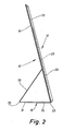
- This stand holder has a casing 12 comprising a top wall 13 and a rear wall 14 and a stand formed from a tab 15.
- the sleeve 12 is closed in itself and has a corresponding cavity for the calendar 11.
- this is designed in a special way, namely it is composed of a flat calendar rear wall 16 made of a cardboard-like material and a stack of loose calendar pages 17.
- the latter are arranged as a stack on the calendar rear wall 16 and have a smaller format than the latter, namely a smaller height with approximately the same width.
- the calendar rear wall 16 protrudes both on the underside and on the top with strip-shaped end regions 18 and 19 relative to the stack of calendar sheets 17.
- the end regions 18 and 19 can be used as advertising spaces.
- the upper end region 18 in FIG. 1 has the imprint "nimi".
- the calendar pages 17 are alternately printed with a calendar, which in the present exemplary embodiment is designed in the form of a "three-month calendar". Accordingly, three consecutive months are shown one above the other on the calendar pages 17, of which the middle month corresponds to the respective current month, while the upper month indicates the previous month and the lower month the following month. For the sake of clarity, the current (middle) month (here: January 1987) compared to the other two months naten shown in a different color.
- the top wall 13 and the back wall 14 are congruent with a rectangular base.
- the rear wall 14 has a circumferential projection 20, viewed in relation to the side facing the top wall 13, which engages from the underside of the top wall 13 in a corresponding recess 21 arranged thereon in a form-fitting manner.
- This configuration of the edges of the top wall 13 and the rear wall 14 results in a circumferential frame 22 with slightly rounded corners running on the casing 12 at a slight distance from the edges.
- the frame surrounds an inner visible surface 23 of the top wall 13, which corresponds approximately to the format of the calendar rear wall 16.
- the visible surface 23 is at a sufficiently large distance from the corresponding inner surface 24 of the rear wall 14 in order to accommodate the calendar rear wall in the cover 12 in a form-fitting manner.
- the visible surface 23 of the top wall 13 also has an elevation 25 which extends over the entire width of the visible surface 23 and is adapted in length to the format of the calendar pages 17, such that the elevation 25 on the visible surface 23 is an additional one Space for receiving the stack of loose calendar pages 17 in the case 12 creates.
- both the projection 20 and the recess 21 have approximately the same profiles, in that they are V-shaped with semicircular rounded apices.
- the sizes of the projection 20 and the recess 21 are selected such that the outer dimension of the projection 20 about the I nnenabunk corresponds to the (larger) or recess is slightly larger to form a bias between the projection 20 and the recess 21st
- the casing 12 in the present exemplary embodiment is assigned a plurality of latching connections 26. These are located on the frame 22, specifically both in the square areas and in the middle of each of the upright (long) sides of the frame 22.
- the latching connections 26 are formed by undercuts shown in FIG. 5, for example.
- both the projection 20 and the recess 21 have cross-sectional constrictions in such a way that, starting from the rounded vertices, the rectilinear regions of the recess 21 and the projection move together.
- 5 shows the latching connection 26 which is assigned to the upright (long) regions of the frame 22 and has two mutually opposite undercuts. In a departure from this, the latching connections 26 are formed in the corner regions of the frame 22, which namely have only one undercut on the outside.
- FIGS. 1 and 3 A date marking particularly suitable for the sleeve 12 according to the invention is shown in FIGS. 1 and 3.
- This consists of a strip-shaped carrier 27 made of a clear material, on which a colored date display 28 of the usual type is arranged so that it can be moved up and down.
- the carrier 27 is in turn slidably mounted on the top wall 13 in the horizontal direction, in the region of the elevation 25 thereof.
- the elevation 25 has two elongated incisions 29 which run parallel to one another and at a distance from one another and which can be formed, for example, by corresponding punchings on the visible surface 23.
- the U-shaped flanged ends 30 of the carrier 27 protrude through the incisions 29 for fastening the latter to the top wall 13.
- the width of the incisions 29 is seven columns for the Weekdays limited. An accidental assignment of the carrier 27 with the date display 28 to the (left) weekly column is therefore not possible.
- the length of the incisions 29 can be limited to the columns of the working days, so that only these can be marked.
- a stand 31 for the cover 12 is formed here by a tab 15.
- this is an integral part of the rear wall 14 in that it is arranged on the (narrow) underside of the latter and is delimited from it by a stamping line 33 or a fold.
- the flap 15 can therefore be folded back like a hinge around the embossing line 33.
- the tab 15 for V-shaped buckling is again divided into a foot part 34 serving as a standing surface and an adjoining support part 35.
- the latter is designed to taper towards the free end as shown in FIG. 6.
- the free end of the support part 35 has opposite notches 36 to form an insertion tab 37.
- the insertion tab 37 is to be inserted as shown in FIG. 3 through a corresponding slot 38 in the inner surface 24 of the rear wall 14.
- the stand holder 10 is shown in a still open, unwound state. It can be seen that the entire stand consists of one piece, namely the top wall 13, the rear wall 14 and the tab 15 of the stand 31 are connected to one another.
- a (narrow) edge of the top wall 13 is connected to an adjacent edge of the rear wall 14 in a hinge-like manner by an embossing line 39 4 creates a permanent connection of a (narrow) side between the top wall 13 and the rear wall 14 when they are pivoted to form the shell 12.
- the entire stand 10 can be produced in this way from a single blank with a base area shown in FIG. 6, preferably by deep drawing and subsequent stamping or stamping. If the stand 10 is to be used as a hanging holder, the (lower) tab 15 can alternatively also be used. However, it is also possible to separate the tab 15 from the rear wall 14 after the manufacture of the stand holder 10, if this is not required, that is to say the stand holder is to be used as a hanging holder.
- the rear wall 14 of the article holder has 1o nor a suspension plate 4 0, the manner known per se is formed as a "Euro tab" as used herein in the art.
- the stand holder 10 can alternatively be used as a hanging holder.
- the sleeve 12 shown in FIG. 6 also has three stops 41 in the present case, which are assigned to the rear wall 14 and protrude from the inner surface 24 thereof. Corresponding to the stops 41 are openings in the calendar rear wall 16 for the passage of the stops 41.
- the positioning of the stops 41 on the inner surface 24 of the rear wall 14 is such that the stops 41 protrude into the elevation 25 assigned to the top wall 13, specifically in the lower area of the same.
- the calendar sheets 17 come to rest with their lower edges on the stops 41.
- the stops 41 thus form a (lower) system for the calendar pages 17 to prevent individual slipping down Calendar pages 17 in the end area 19 located under the elevation 25.
Landscapes
- Mirrors, Picture Frames, Photograph Stands, And Related Fastening Devices (AREA)
- Sheet Holders (AREA)
Applications Claiming Priority (2)
| Application Number | Priority Date | Filing Date | Title |
|---|---|---|---|
| DE8625386U | 1986-09-23 | ||
| DE19868625386 DE8625386U1 (de) | 1986-09-23 | 1986-09-23 | Halter, insbesondere Standhalter für einen Kalender o.dgl. |
Publications (2)
| Publication Number | Publication Date |
|---|---|
| EP0261277A2 true EP0261277A2 (fr) | 1988-03-30 |
| EP0261277A3 EP0261277A3 (fr) | 1989-05-03 |
Family
ID=6798536
Family Applications (1)
| Application Number | Title | Priority Date | Filing Date |
|---|---|---|---|
| EP86115603A Withdrawn EP0261277A3 (fr) | 1986-09-23 | 1986-11-11 | Support, notamment vertical pour calendrier ou autres choses semblables |
Country Status (2)
| Country | Link |
|---|---|
| EP (1) | EP0261277A3 (fr) |
| DE (1) | DE8625386U1 (fr) |
Cited By (3)
| Publication number | Priority date | Publication date | Assignee | Title |
|---|---|---|---|---|
| EP0333895A1 (fr) * | 1988-03-22 | 1989-09-27 | B. C. Heye & Co. GmbH | Calendrier, en particulier calendrier de table |
| GB2355551A (en) * | 1999-08-18 | 2001-04-25 | Drukkerij Stockmans Nv | Desktop information carrier |
| GB2356944A (en) * | 1999-12-04 | 2001-06-06 | Caltime Ltd | Date card holder |
Family Cites Families (13)
| Publication number | Priority date | Publication date | Assignee | Title |
|---|---|---|---|---|
| DE7342263U (de) * | 1974-04-18 | Schwaiger K | Wechselrahmen für Kalenderblätter | |
| DE8106466U1 (de) * | 1981-08-13 | Fotocolor Wermbter GmbH, 7800 Freiburg | "Kalender" | |
| FR384091A (fr) * | 1906-11-17 | 1908-03-28 | John Frederick Bennet | Calendrier |
| GB313039A (en) * | 1928-06-05 | 1930-01-02 | Julius Schroeder | An advertisement calendar |
| GB426220A (en) * | 1933-11-03 | 1935-03-29 | Charles Frederick Gaunt | Improvements in or relating to date indicators |
| US2093160A (en) * | 1936-08-14 | 1937-09-14 | Steinthal Martin | Sample holder and easel therefor |
| US2208213A (en) * | 1938-11-28 | 1940-07-16 | Barrett Bindery Co | Display binder |
| DE1825522U (de) * | 1960-12-02 | 1961-01-26 | Polyprint Ag | Kalender. |
| GB1198091A (en) * | 1967-03-08 | 1970-07-08 | Evershed & Company Bow Ltd J | Improvements in or relating to Calendars |
| DE8410073U1 (de) * | 1984-03-31 | 1985-07-25 | IKUSTO GmbH Industrie-, Kunststoffspritzguss- und Extrudierwerk - eigener Stahlformenbau, 8933 Untermeitingen | Wandkalender |
| DE8412831U1 (de) * | 1984-04-26 | 1984-08-09 | Bertram Etiketten GmbH, 2000 Hamburg | Vorrichtung zum Aufstellen von Tischkalendern od. dgl. |
| DE8424369U1 (de) * | 1984-08-17 | 1985-02-28 | Fengler, Horst, 4902 Bad Salzuflen | Gehäuse für Kalenderblätter |
| DE8427002U1 (de) * | 1984-09-13 | 1984-12-06 | Georg Gebhardt Großbuchbinderei, 8800 Ansbach | Kalender |
-
1986
- 1986-09-23 DE DE19868625386 patent/DE8625386U1/de not_active Expired
- 1986-11-11 EP EP86115603A patent/EP0261277A3/fr not_active Withdrawn
Cited By (4)
| Publication number | Priority date | Publication date | Assignee | Title |
|---|---|---|---|---|
| EP0333895A1 (fr) * | 1988-03-22 | 1989-09-27 | B. C. Heye & Co. GmbH | Calendrier, en particulier calendrier de table |
| GB2355551A (en) * | 1999-08-18 | 2001-04-25 | Drukkerij Stockmans Nv | Desktop information carrier |
| GB2355551B (en) * | 1999-08-18 | 2003-11-05 | Drukkerij Stockmans Nv | Desktop information carrier |
| GB2356944A (en) * | 1999-12-04 | 2001-06-06 | Caltime Ltd | Date card holder |
Also Published As
| Publication number | Publication date |
|---|---|
| EP0261277A3 (fr) | 1989-05-03 |
| DE8625386U1 (de) | 1987-01-02 |
Similar Documents
| Publication | Publication Date | Title |
|---|---|---|
| DE8331210U1 (de) | Kanten- oder Eckbeschlag | |
| EP0946935A2 (fr) | Motif de pliage | |
| EP0499152B1 (fr) | Classeur ou similaire | |
| EP0261277A2 (fr) | Support, notamment vertical pour calendrier ou autres choses semblables | |
| EP0384449B1 (fr) | Réceptacle | |
| DE69225234T2 (de) | Aufhängevorrichtung für verpackungen | |
| DE238384T1 (de) | Schauverpackung fuer mehrere in reihe gestellte trinkglaeser oder gleiche artikel. | |
| DE3118695C2 (de) | Haltevorrichtung für Prospekte u.dgl. | |
| DE8712480U1 (de) | Halter, insbesondere Standhalter für einen Kalender o. dgl. | |
| DE2164201C3 (de) | Werbeaufsteller | |
| DE3604382A1 (de) | Kalender | |
| EP0261434B1 (fr) | Calendrier, en particulier calendrier disposé verticalement | |
| DE2648312A1 (de) | Immerwaehrender kalender | |
| EP0864503A2 (fr) | Emballage pour support de tableau, en particulier pour support de tableau sans cadre | |
| EP0333895A1 (fr) | Calendrier, en particulier calendrier de table | |
| DE69800273T2 (de) | Behälter zur Aufnahme eines Notizblocks | |
| DE3217133A1 (de) | Warenverkaufsstaender | |
| DE2840426C2 (de) | Palette | |
| DE8200650U1 (de) | Notizzettelbehaelter | |
| DE3815945A1 (de) | Rahmen zur aufnahme eines plakatartigen informationstraegers | |
| DE8410073U1 (de) | Wandkalender | |
| DE29702992U1 (de) | Etui | |
| DE6942106U (de) | Aufstellplakat | |
| DE9006267U1 (de) | Verpackungsschachtel für Waren | |
| DE3138552A1 (de) | "bueroreitersystem" |
Legal Events
| Date | Code | Title | Description |
|---|---|---|---|
| PUAI | Public reference made under article 153(3) epc to a published international application that has entered the european phase |
Free format text: ORIGINAL CODE: 0009012 |
|
| AK | Designated contracting states |
Kind code of ref document: A2 Designated state(s): AT BE CH DE GB LI NL |
|
| PUAL | Search report despatched |
Free format text: ORIGINAL CODE: 0009013 |
|
| AK | Designated contracting states |
Kind code of ref document: A3 Designated state(s): AT BE CH DE GB LI NL |
|
| STAA | Information on the status of an ep patent application or granted ep patent |
Free format text: STATUS: THE APPLICATION IS DEEMED TO BE WITHDRAWN |
|
| 18D | Application deemed to be withdrawn |
Effective date: 19891104 |