EP0261306A2 - Rotor pour moteurs électriques blindés ventilés - Google Patents
Rotor pour moteurs électriques blindés ventilés Download PDFInfo
- Publication number
- EP0261306A2 EP0261306A2 EP87106210A EP87106210A EP0261306A2 EP 0261306 A2 EP0261306 A2 EP 0261306A2 EP 87106210 A EP87106210 A EP 87106210A EP 87106210 A EP87106210 A EP 87106210A EP 0261306 A2 EP0261306 A2 EP 0261306A2
- Authority
- EP
- European Patent Office
- Prior art keywords
- winding
- cage
- webs
- anchor
- armature
- Prior art date
- Legal status (The legal status is an assumption and is not a legal conclusion. Google has not performed a legal analysis and makes no representation as to the accuracy of the status listed.)
- Withdrawn
Links
Images

Classifications
-
- H—ELECTRICITY
- H02—GENERATION; CONVERSION OR DISTRIBUTION OF ELECTRIC POWER
- H02K—DYNAMO-ELECTRIC MACHINES
- H02K9/00—Arrangements for cooling or ventilating
- H02K9/26—Structural association of machines with devices for cleaning or drying cooling medium, e.g. with filters
-
- H—ELECTRICITY
- H02—GENERATION; CONVERSION OR DISTRIBUTION OF ELECTRIC POWER
- H02K—DYNAMO-ELECTRIC MACHINES
- H02K3/00—Details of windings
-
- H—ELECTRICITY
- H02—GENERATION; CONVERSION OR DISTRIBUTION OF ELECTRIC POWER
- H02K—DYNAMO-ELECTRIC MACHINES
- H02K3/00—Details of windings
- H02K3/04—Windings characterised by the conductor shape, form or construction, e.g. with bar conductors
- H02K3/24—Windings characterised by the conductor shape, form or construction, e.g. with bar conductors with channels or ducts for cooling medium between the conductors
-
- H—ELECTRICITY
- H02—GENERATION; CONVERSION OR DISTRIBUTION OF ELECTRIC POWER
- H02K—DYNAMO-ELECTRIC MACHINES
- H02K3/00—Details of windings
- H02K3/32—Windings characterised by the shape, form or construction of the insulation
- H02K3/38—Windings characterised by the shape, form or construction of the insulation around winding heads, equalising connectors, or connections thereto
-
- H—ELECTRICITY
- H02—GENERATION; CONVERSION OR DISTRIBUTION OF ELECTRIC POWER
- H02K—DYNAMO-ELECTRIC MACHINES
- H02K3/00—Details of windings
- H02K3/46—Fastening of windings on the stator or rotor structure
- H02K3/50—Fastening of winding heads, equalising connectors, or connections thereto
- H02K3/51—Fastening of winding heads, equalising connectors, or connections thereto applicable to rotors only
-
- H—ELECTRICITY
- H02—GENERATION; CONVERSION OR DISTRIBUTION OF ELECTRIC POWER
- H02K—DYNAMO-ELECTRIC MACHINES
- H02K9/00—Arrangements for cooling or ventilating
- H02K9/02—Arrangements for cooling or ventilating by ambient air flowing through the machine
- H02K9/04—Arrangements for cooling or ventilating by ambient air flowing through the machine having means for generating a flow of cooling medium
- H02K9/06—Arrangements for cooling or ventilating by ambient air flowing through the machine having means for generating a flow of cooling medium with fans or impellers driven by the machine shaft
Definitions
- the invention relates to an anchor for high-speed, draft-ventilated electric motors, in particular for use in power tools, with a winding formed from a plurality of wire windings, which is arranged in the longitudinal grooves of an iron packet sitting on a shaft and at the two ends of which an axially projecting one Winding head forms.
- Such anchors which are strictly speaking the rotor of the electric motor, on the shaft of which an output pinion is usually seated, are subjected to considerable stresses in the through-ventilation of the motor due to the impact of solid particles carried in the cooling air flow.
- the cooling air conveys considerable amounts of dust and dirt particles through the machine. These particles hit the winding heads of the armature winding with a considerable relative speed, because a speed component is also added to the flow speed, which is due to the rotation of the armature.
- the armature rotors of universal motors as they are generally used today in power tools, have not only idle speeds but also working speeds in the order of more than 10,000 rpm.
- the invention is based on the object of providing an armature for such ventilated electric motors of the generic type, in which effective protection of the armature winding against impacts of solid particles carried in the cooling air flow is achieved with simple means, without the cooling of the armature being significantly impaired becomes.
- At least one of the two winding heads has protruding ribs which are spaced apart from one another and which extend along surface lines in the longitudinal direction of the armature or at least essentially in this direction and between which exposed locations of the winding head are located .
- an armature according to the invention for electric motors is that the protruding ribs applied to the winding head act as deflectors, which results from the dynamic state due to the high armature speeds and not from the covering or shading of the winding head concerned by the ribs located on it results. Only in this way can the ribs have such a distance from one another that a sufficient cooling surface remains free between them on the winding head, which can be flushed with the cooling air, from which the solid particles are eliminated due to the entrainment by the ribs. Practical tests have confirmed the effectiveness of the external ribbing on the armature winding heads as a deflector for the particles carried in the cooling air flow.
- the deflector ribs are applied at least to the winding head, which is more heavily loaded by the solid particles, but preferably to both winding heads of the armature.
- You are as Parts of a cage that can be placed on the winding overhangs are easy to manufacture and attach, wherein, depending on the customary configuration of the winding overhangs for the armature of collector motors, such a cage is somewhat frustoconical or spherical.
- An exact adaptation of the cage to the irregularities of the windings, which also differ for different voltages, is generally not possible and, above all, is not necessary for the important deflector function.
- the attached cage is connected to the relevant winding head preferably in a rotationally fixed manner via a protective medium, such as a trickling resin.
- the cage does not interfere electrically or magnetically, it is suitably made of an insulating material.
- the total area of the openings between the cage webs is advantageously chosen to be the same size or larger than the area covered by the cage webs themselves. The purely mechanical protection provided by the cage webs due to the covering of winding end parts is virtually negligible.
- FIG. 1 shows a rotor armature 1 which has an iron package 3 which is seated on an armature shaft 2 and which is essentially cylindrical.
- the iron package 3 has longitudinal grooves 4, in which a winding of wire windings with enamel insulation, which cannot be seen in the drawing, is embedded.
- a radially acting fan 5 is also arranged on the armature shaft 2 on the outflow side of the armature, while a collector 6 is seated on the shaft 2 on the opposite armature side.
- Extending between the collector 6 and the iron package 3 is a first upstream winding end 7, which is formed from the winding sections closing between the grooves 4 of the iron package 3 and from the wire sections leading to the collector 6.
- the winding head 7 has the shape of a truncated cone or section.
- winding head 8 On the opposite armature side there is a further winding head 8, which is formed by the winding sections, which here on the end face consist of the grooves 4 of the iron packet 3 out and re-enter other grooves. Essentially, there is an envelope of the winding head 8 in the form of a spherical section which is somewhat flattened towards the end.
- Ribs 9 are applied to both end windings 7 and 8 and extend essentially along outer surface lines of the end windings 7, 8 in the longitudinal direction of the armature.
- the ribs 9 protrude on the outer sides of the end windings 7, 8 in the radial direction and each extend between two ring webs 10, with which they form an integral cage 11.
- the ribs 9 have a rectangular cross-section and are thus arranged upright on the top of the end winding.
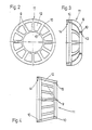
- FIGS. 2 and 3 A first embodiment of such a cage 11, which serves to cover the winding head 8 on the fan side, is shown in detail in FIGS. 2 and 3. Its shape in the form of an arcuate or parabolic rotating body is adapted to that of the winding head 8 (FIG. 1) in such a way that the outer contour of the winding head 8 fits essentially positively into the interior of the basket-like cage 11.
- the individual webs of the cage 11 forming the ribs 9 are arranged at a distance from one another, so that openings 12 are formed between them. In the area of these openings 12, the sections of the winding head 8 arranged underneath are exposed, so that, despite partial covering, a sufficient cooling surface of the winding head is still available.
- the total area of the openings 12 of the cage 11 is the same size or larger than the area covered by the rib webs 9 and ring webs 10 of the cage 11.
- the smaller, outer ring web 10, into which the ribs 9 open radially, has a bore 13 on the inside, which forms a fit with the relevant section in the vicinity of the fan 5 of the armature shaft 1, so that the cage 11 in the Operating position is exactly centered.
- the ring 10 at the opposite end of the cage 11, into which the ribs 9 open approximately axially parallel, has an internal recess 14 with which the assembled cage 11 is pushed onto an end plate 16 shown in FIG. 1 on the end face of the iron package 3.
- FIG. 4 shows a cage 11 which, in the same way as that according to FIGS. 2 and 3, consists of rib webs 9 extending between two ring webs 10.
- the ring webs 10 running in the armature circumferential direction in the operating position are fixed in a coaxial position by intermediate or end plates 16, so that there are no imbalances.
- the cage 11, which is approximately frustoconical here, is adapted to the collector-side winding head 7 of the armature shown in FIG. 1. In the interior of its ring webs 10, it has internal cutouts 14 and 15 which overlap the disks mentioned, which are seated centrally on the armature shaft 2.
- the cages 11 can fulfill their task, they must be fixed to the armature 1 in a rotationally fixed manner. This is achieved in a particularly simple manner by using a trickling resin to fix the position Apply windings of the armature winding with or after the cages 11 have been placed on the armature winding and thus on the winding heads 7 and 8. As a result, the cages 11 are glued to the end windings 7 and 8 and additionally secured by a slight positive connection.
- the cage 11 can also have the shape of a basket with irregular webs and irregularly arranged openings. It is only important that the webs do not all run in the circumferential direction but have a direction which has a clear component in the axial direction of the armature so that the desired rejection of the solid particles carried in the cooling air flow can take place.
- the cage or basket can also have webs which do not meet this requirement.
Landscapes
- Engineering & Computer Science (AREA)
- Power Engineering (AREA)
- Motor Or Generator Cooling System (AREA)
- Insulation, Fastening Of Motor, Generator Windings (AREA)
- Windings For Motors And Generators (AREA)
- Iron Core Of Rotating Electric Machines (AREA)
Applications Claiming Priority (2)
| Application Number | Priority Date | Filing Date | Title |
|---|---|---|---|
| DE3632771 | 1986-09-26 | ||
| DE3632771 | 1986-09-26 |
Publications (2)
| Publication Number | Publication Date |
|---|---|
| EP0261306A2 true EP0261306A2 (fr) | 1988-03-30 |
| EP0261306A3 EP0261306A3 (fr) | 1988-10-19 |
Family
ID=6310438
Family Applications (1)
| Application Number | Title | Priority Date | Filing Date |
|---|---|---|---|
| EP87106210A Withdrawn EP0261306A3 (fr) | 1986-09-26 | 1987-04-29 | Rotor pour moteurs électriques blindés ventilés |
Country Status (2)
| Country | Link |
|---|---|
| US (1) | US4800315A (fr) |
| EP (1) | EP0261306A3 (fr) |
Cited By (10)
| Publication number | Priority date | Publication date | Assignee | Title |
|---|---|---|---|---|
| DE3824234A1 (de) * | 1988-07-16 | 1990-01-25 | Bosch Gmbh Robert | Handwerkzeugmaschine mit durchzugsbelueftetem antriebsmotor |
| EP0444908A3 (en) * | 1990-02-28 | 1991-11-06 | Black & Decker Inc. | Armature for an electric motor |
| GB2436944A (en) * | 2006-03-29 | 2007-10-10 | Bosch Gmbh Robert | Cooling an armature using a heat conducting element. |
| WO2007118483A1 (fr) * | 2006-04-06 | 2007-10-25 | Metabowerke Gmbh | Induit pour un moteur électrique ventilé |
| EP2237394A2 (fr) | 2009-04-02 | 2010-10-06 | Metabowerke GmbH | Induit pour un moteur électrique avec ventilation à air forcé |
| DE102011053138A1 (de) | 2011-08-31 | 2013-02-28 | Ebm-Papst Mulfingen Gmbh & Co. Kg | "Elektrischer Außenläufermotor mit Nutkühlung" |
| FR2984625A1 (fr) * | 2011-12-20 | 2013-06-21 | Valeo Equip Electr Moteur | Rotor a poles saillants comportant des flasques de maintien des chignons de bobinages et flasques de maintien associes |
| DE102013212958A1 (de) | 2013-07-03 | 2015-01-22 | Metabowerke Gmbh | Rotor eines durchzugsbelüfteten Elektromotors |
| CN105940594A (zh) * | 2013-12-12 | 2016-09-14 | 万高电机设备公司 | 用于将内部空气偏转器附接到旋转电机的偏转器盖的系统 |
| CN112311115A (zh) * | 2019-09-20 | 2021-02-02 | 浙江磐龙机电有限公司 | 一种具有调节护环过盈量的大功率异步电机转子 |
Families Citing this family (17)
| Publication number | Priority date | Publication date | Assignee | Title |
|---|---|---|---|---|
| USD320191S (en) | 1988-11-30 | 1991-09-24 | Mabuchi Motor Co., Ltd. | Rotor of an electric motor |
| JP3373695B2 (ja) * | 1995-05-24 | 2003-02-04 | 株式会社マキタ | 電動工具用モータの回転子 |
| GB9811457D0 (en) * | 1998-05-29 | 1998-07-29 | Johnson Electric Sa | Rotor |
| US6350124B1 (en) * | 1999-10-22 | 2002-02-26 | Eric Wade | Prophylactic systems for dental instruments and methods for using the same |
| US7096566B2 (en) | 2001-01-09 | 2006-08-29 | Black & Decker Inc. | Method for making an encapsulated coil structure |
| CZ20031901A3 (cs) * | 2001-01-09 | 2003-11-12 | Black & Decker Inc. | Elektrický motor s kotvou potaženou tepelně vodivým plastem |
| US20020089240A1 (en) | 2001-01-09 | 2002-07-11 | Du Hung T. | Electric motor having armature coated with a thermally conductive plastic |
| US6946758B2 (en) * | 2001-01-09 | 2005-09-20 | Black & Decker Inc. | Dynamoelectric machine having encapsulated coil structure with one or more of phase change additives, insert molded features and insulated pinion |
| US7814641B2 (en) * | 2001-01-09 | 2010-10-19 | Black & Decker Inc. | Method of forming a power tool |
| US20040056539A1 (en) * | 2001-11-30 | 2004-03-25 | Du Hung T. | Electric motor having armature coated with a thermally conductive plastic |
| JP4595442B2 (ja) * | 2004-08-24 | 2010-12-08 | 日立工機株式会社 | 電動モータ、それを備える電動工具及び電動モータの製造方法 |
| US8777120B2 (en) * | 2006-04-15 | 2014-07-15 | International Business Machines Corporation | Hydronic radiant flooring heating system |
| CN101917102B (zh) * | 2010-07-12 | 2012-06-06 | 无锡锡山安达防爆电气设备有限公司 | 具有导风板的三相异步电动机空心轴 |
| KR20130013143A (ko) * | 2011-07-27 | 2013-02-06 | 삼성전기주식회사 | 초음파 센서 |
| US9973049B2 (en) | 2013-03-15 | 2018-05-15 | Techtronic Industries Co. Ltd. | Electric motor |
| US9653967B2 (en) | 2013-03-15 | 2017-05-16 | Techtronic Power Tools Technology Limited | Cooling arrangement for an electric motor |
| US9555554B2 (en) | 2013-05-06 | 2017-01-31 | Milwaukee Electric Tool Corporation | Oscillating multi-tool system |
Family Cites Families (11)
| Publication number | Priority date | Publication date | Assignee | Title |
|---|---|---|---|---|
| US967240A (en) * | 1908-11-06 | 1910-08-16 | Westinghouse Electric & Mfg Co | Coil-supporting structure for dynamo-electric machines. |
| US1803493A (en) * | 1927-11-12 | 1931-05-05 | Volet Rene Alfred Laurent | Rotor |
| US2319194A (en) * | 1941-12-05 | 1943-05-11 | Casco Products Corp | Electric motor |
| US2381533A (en) * | 1943-12-30 | 1945-08-07 | Independent Pneumatic Tool Co | Motor armature |
| DE905869C (de) * | 1950-12-09 | 1954-03-08 | Hoover Ltd | Anker fuer dynmaoelektrische Maschinen, bei dem die Wicklungen in den Nuten durch kreisfoermige Festhaltebaender gehalten werden |
| DE904205C (de) * | 1951-12-07 | 1954-02-15 | Heinz Luebeck Dr Ing | Flachkollektor, insbesondere fuer Kleinstmotoren |
| DE1613189A1 (de) * | 1967-01-05 | 1970-04-23 | Licentia Gmbh | Anordnung zum Auswuchten von bewickelten Laeufern elektrischer Maschinen und zum Kuehlen der Wicklungen |
| DE2225203A1 (de) * | 1972-05-24 | 1973-12-06 | Schorch Gmbh | Verfahren zur lagefixierung der freiliegenden wicklungsteile elektrischer maschinen |
| DE2555529C3 (de) * | 1975-12-10 | 1985-05-30 | SWF Auto-Electric GmbH, 7120 Bietigheim-Bissingen | Elektromotor für eine Flüssigkeitspumpe mit einem von der Flüssigkeit umströmten Anker |
| DE2620917A1 (de) * | 1976-05-12 | 1977-12-01 | Vorwerk & Co Elektrowerke Kg | Verfahren und anordnung zum festlegen freier wicklungsenden von rotorwicklungen durch impraegnieren |
| US4636669A (en) * | 1984-10-29 | 1987-01-13 | Msl Industries, Inc. | Termination assembly for electric fans |
-
1987
- 1987-04-29 EP EP87106210A patent/EP0261306A3/fr not_active Withdrawn
- 1987-09-17 US US07/097,710 patent/US4800315A/en not_active Expired - Fee Related
Cited By (17)
| Publication number | Priority date | Publication date | Assignee | Title |
|---|---|---|---|---|
| DE3824234A1 (de) * | 1988-07-16 | 1990-01-25 | Bosch Gmbh Robert | Handwerkzeugmaschine mit durchzugsbelueftetem antriebsmotor |
| EP0444908A3 (en) * | 1990-02-28 | 1991-11-06 | Black & Decker Inc. | Armature for an electric motor |
| GB2436944A (en) * | 2006-03-29 | 2007-10-10 | Bosch Gmbh Robert | Cooling an armature using a heat conducting element. |
| GB2436944B (en) * | 2006-03-29 | 2009-04-01 | Bosch Gmbh Robert | Electric machine |
| US7732954B2 (en) | 2006-03-29 | 2010-06-08 | Robert Bosch Gmbh | Electrical machine |
| WO2007118483A1 (fr) * | 2006-04-06 | 2007-10-25 | Metabowerke Gmbh | Induit pour un moteur électrique ventilé |
| US7696663B2 (en) | 2006-04-06 | 2010-04-13 | Metabowerke Gmbh | Rotor for a forced-air-cooled electric motor |
| CN101416371B (zh) * | 2006-04-06 | 2011-06-01 | 麦太保有限公司 | 用于强制通风冷却的电动机的电枢 |
| DE102009016024A1 (de) | 2009-04-02 | 2010-10-07 | Metabowerke Gmbh | Anker für einen durchzugsbelüfteten Elektromotor |
| EP2237394A2 (fr) | 2009-04-02 | 2010-10-06 | Metabowerke GmbH | Induit pour un moteur électrique avec ventilation à air forcé |
| DE102011053138A1 (de) | 2011-08-31 | 2013-02-28 | Ebm-Papst Mulfingen Gmbh & Co. Kg | "Elektrischer Außenläufermotor mit Nutkühlung" |
| FR2984625A1 (fr) * | 2011-12-20 | 2013-06-21 | Valeo Equip Electr Moteur | Rotor a poles saillants comportant des flasques de maintien des chignons de bobinages et flasques de maintien associes |
| EP2608363A1 (fr) * | 2011-12-20 | 2013-06-26 | Valeo Equipements Electriques Moteur | Flasques de maintien des chignons de bobinages et rotor à pôles saillants comportant lesdites flasques |
| DE102013212958A1 (de) | 2013-07-03 | 2015-01-22 | Metabowerke Gmbh | Rotor eines durchzugsbelüfteten Elektromotors |
| CN105940594A (zh) * | 2013-12-12 | 2016-09-14 | 万高电机设备公司 | 用于将内部空气偏转器附接到旋转电机的偏转器盖的系统 |
| CN112311115A (zh) * | 2019-09-20 | 2021-02-02 | 浙江磐龙机电有限公司 | 一种具有调节护环过盈量的大功率异步电机转子 |
| CN112311115B (zh) * | 2019-09-20 | 2022-05-24 | 浙江磐龙机电有限公司 | 一种具有调节护环过盈量的大功率异步电机 |
Also Published As
| Publication number | Publication date |
|---|---|
| EP0261306A3 (fr) | 1988-10-19 |
| US4800315A (en) | 1989-01-24 |
Similar Documents
| Publication | Publication Date | Title |
|---|---|---|
| EP0261306A2 (fr) | Rotor pour moteurs électriques blindés ventilés | |
| DE1291012B (de) | Elektrischer Drehstromgenerator, insbesondere fuer Kraftfahrzeuge | |
| WO2010072496A2 (fr) | Machine électrique à courant de refroidissement déplacé radialement, et procédé de refroidissement | |
| DE2334637B2 (de) | Durchzugsbelüftete elektrische Maschine | |
| DE3242018A1 (de) | Kuehlvorrichtung fuer eine elektrische rotationsmaschine | |
| DE10261434A1 (de) | Isolierter Statorkern mit Befestigungsmerkmalen | |
| DE1939184A1 (de) | Anordnung zur Kuehlung der Rotoren elektrischer Maschinen,insbesondere elektrischer Kleinmotoren | |
| WO2019171218A1 (fr) | Unité rotor et moteur électrique | |
| DE2262045A1 (de) | Turbogenerator | |
| CH659552A5 (de) | Rotor fuer elektrische rotationsmaschine. | |
| WO2019171219A1 (fr) | Unité rotor et moteur électrique | |
| DE102009001745A1 (de) | Klauenpol mit Zentrierpunkt | |
| EP1155490A1 (fr) | Generateur a poles a griffes avec amortissement des oscillations | |
| DE8625788U1 (de) | Anker für durchzugsbelüftete Elektromotoren | |
| EP2002527B1 (fr) | Induit pour un moteur électrique ventilé | |
| DE29821112U1 (de) | Anker mit Schutzkorb für durchzugsbelüftete Elektromotoren | |
| DE3230296C2 (fr) | ||
| DE69610375T2 (de) | Elektrische drehende Maschine mit abnehmbarer schutzender Abdeckung und schutzende Abdeckung für eine solche Maschine | |
| WO2020012274A1 (fr) | Unité de rotor pour un moteur électrique sans balai pourvu de conducteurs de flux magnétique d'une seule pièce | |
| EP0074020B1 (fr) | Machine synchrone | |
| DE877034C (de) | Belueftung fuer elektrische Maschinen, bei der die Kuehlluft auf der einen Maschinenseite eintritt und die Maschine im wesentlichen axial in parallelen Zweigen durchstroemt | |
| AT517967B1 (de) | Luftgekühlte elektrische Maschine | |
| EP2237394A2 (fr) | Induit pour un moteur électrique avec ventilation à air forcé | |
| DE102007053313A1 (de) | Anker für schnell laufende Elektromotoren | |
| EP2091135A1 (fr) | Induit pour un moteur électrique avec ventilation à air forcé |
Legal Events
| Date | Code | Title | Description |
|---|---|---|---|
| PUAI | Public reference made under article 153(3) epc to a published international application that has entered the european phase |
Free format text: ORIGINAL CODE: 0009012 |
|
| AK | Designated contracting states |
Kind code of ref document: A2 Designated state(s): CH DE FR GB IT LI |
|
| PUAL | Search report despatched |
Free format text: ORIGINAL CODE: 0009013 |
|
| AK | Designated contracting states |
Kind code of ref document: A3 Designated state(s): CH DE FR GB IT LI |
|
| STAA | Information on the status of an ep patent application or granted ep patent |
Free format text: STATUS: THE APPLICATION HAS BEEN WITHDRAWN |
|
| 18W | Application withdrawn |
Withdrawal date: 19881215 |
|
| RIN1 | Information on inventor provided before grant (corrected) |
Inventor name: WAGEMANN, ALFRED Inventor name: SCHULZ, MANFRED, DIPL.-ING. Inventor name: WALDNER, GERHARD |