EP0261321A2 - Fermeture de ceinture ou analogue - Google Patents
Fermeture de ceinture ou analogue Download PDFInfo
- Publication number
- EP0261321A2 EP0261321A2 EP87109293A EP87109293A EP0261321A2 EP 0261321 A2 EP0261321 A2 EP 0261321A2 EP 87109293 A EP87109293 A EP 87109293A EP 87109293 A EP87109293 A EP 87109293A EP 0261321 A2 EP0261321 A2 EP 0261321A2
- Authority
- EP
- European Patent Office
- Prior art keywords
- window
- cover
- rail
- tongue
- Prior art date
- Legal status (The legal status is an assumption and is not a legal conclusion. Google has not performed a legal analysis and makes no representation as to the accuracy of the status listed.)
- Withdrawn
Links
Images

Classifications
-
- A—HUMAN NECESSITIES
- A41—WEARING APPAREL
- A41F—GARMENT FASTENINGS; SUSPENDERS
- A41F1/00—Fastening devices specially adapted for garments
- A41F1/008—Adjustable fasteners comprising a track and a slide member
-
- Y—GENERAL TAGGING OF NEW TECHNOLOGICAL DEVELOPMENTS; GENERAL TAGGING OF CROSS-SECTIONAL TECHNOLOGIES SPANNING OVER SEVERAL SECTIONS OF THE IPC; TECHNICAL SUBJECTS COVERED BY FORMER USPC CROSS-REFERENCE ART COLLECTIONS [XRACs] AND DIGESTS
- Y10—TECHNICAL SUBJECTS COVERED BY FORMER USPC
- Y10S—TECHNICAL SUBJECTS COVERED BY FORMER USPC CROSS-REFERENCE ART COLLECTIONS [XRACs] AND DIGESTS
- Y10S24/00—Buckles, buttons, clasps
- Y10S24/30—Separable-fastener or required component thereof
- Y10S24/43—Separable-fastener or required component thereof including member having distinct formations and mating member selectively interlocking therewith
- Y10S24/47—Selectively interlocking member having movably attached or biased interlocking component
- Y10S24/48—And cavity for guiding movement of formations
-
- Y—GENERAL TAGGING OF NEW TECHNOLOGICAL DEVELOPMENTS; GENERAL TAGGING OF CROSS-SECTIONAL TECHNOLOGIES SPANNING OVER SEVERAL SECTIONS OF THE IPC; TECHNICAL SUBJECTS COVERED BY FORMER USPC CROSS-REFERENCE ART COLLECTIONS [XRACs] AND DIGESTS
- Y10—TECHNICAL SUBJECTS COVERED BY FORMER USPC
- Y10T—TECHNICAL SUBJECTS COVERED BY FORMER US CLASSIFICATION
- Y10T24/00—Buckles, buttons, clasps, etc.
- Y10T24/21—Strap tighteners
-
- Y—GENERAL TAGGING OF NEW TECHNOLOGICAL DEVELOPMENTS; GENERAL TAGGING OF CROSS-SECTIONAL TECHNOLOGIES SPANNING OVER SEVERAL SECTIONS OF THE IPC; TECHNICAL SUBJECTS COVERED BY FORMER USPC CROSS-REFERENCE ART COLLECTIONS [XRACs] AND DIGESTS
- Y10—TECHNICAL SUBJECTS COVERED BY FORMER USPC
- Y10T—TECHNICAL SUBJECTS COVERED BY FORMER US CLASSIFICATION
- Y10T24/00—Buckles, buttons, clasps, etc.
- Y10T24/40—Buckles
- Y10T24/4072—Pivoted lever
-
- Y—GENERAL TAGGING OF NEW TECHNOLOGICAL DEVELOPMENTS; GENERAL TAGGING OF CROSS-SECTIONAL TECHNOLOGIES SPANNING OVER SEVERAL SECTIONS OF THE IPC; TECHNICAL SUBJECTS COVERED BY FORMER USPC CROSS-REFERENCE ART COLLECTIONS [XRACs] AND DIGESTS
- Y10—TECHNICAL SUBJECTS COVERED BY FORMER USPC
- Y10T—TECHNICAL SUBJECTS COVERED BY FORMER US CLASSIFICATION
- Y10T24/00—Buckles, buttons, clasps, etc.
- Y10T24/45—Separable-fastener or required component thereof [e.g., projection and cavity to complete interlock]
- Y10T24/45005—Separable-fastener or required component thereof [e.g., projection and cavity to complete interlock] with third detached member completing interlock [e.g., hook type]
- Y10T24/45037—Separable-fastener or required component thereof [e.g., projection and cavity to complete interlock] with third detached member completing interlock [e.g., hook type] for apparel and related accessories
- Y10T24/45063—Belt, strap, etc. [e.g., buckle or snap fastener]
Definitions
- the invention relates to a closure for bundles or the like, in particular on trousers, skirts, bags or the like, consisting of a provided with notches, attached to the one end of the rail and a slide running on this, which is attached to the other end of the collar and which has an angular folding lever, the shorter angle arm engages in the folding position of the folding lever in the locking recesses of the locking rail, has a window for free passage of a cover strip lying on the outside in front of the rail and whose longer angle arm is exposed to the outside as an operating section, the longer angle arm being exposed to an inside Because of the plug-in snap-in connection, the cover is fitted in such a way that the cover has an opening into which a tongue of the angle leg protrudes.
- a closure of this type is known from DE-OS 33 24 657 by the applicant.
- the locking takes place there on the tongue-side frame leg of the window, while the tongue itself sits in the correspondingly cross-sectionally adapted opening.
- a color match can be achieved in particular to the respective item of clothing to which the fastener is assigned.
- the object of the invention is to make the plug-and-snap connection of such a closure structurally simpler and more convenient to assign.
- the folding lever assembly is without Sta loss of balance significantly simplified.
- the cover is then immediately attached.
- the structural means for this are simple and expedient:
- the procedure is such that the opening is designed as an insertion pocket for the tongue that is open towards the window, the wide surface of which engages in a snap connection to the pocket wall.
- Deductible locking and plug seat are combined in one area. It also proves to be advantageous that the pocket wall has on its broad side an entry space for a latching projection of the tongue.
- the other half which forms the free end of the folding lever, remains elastic or flexible depending on the chosen plastic material, so that there, for example, forces acting in the sense of opening do not lead directly to a pivoting of the folding lever into the open position; it rather requires an activity that is stressed by the will, possibly even requiring a slight bending.
- the window-side end section of the cover lies in a recess formed by bending on the top of the frame leg forming the window.
- a flat abutment of cover and corresponding tongue surface is advantageously achieved despite the provision of an edge fold that the edge fold has an interruption in the area of the inserted end section.
- the pocket wide side wall opens into a freely projecting tab, the base line of which is approximately at the level of the window-side edge of the entry space.
- the freely projecting tab is more likely to evade, so that basically the entire pocket area itself is not subject to any deformation in the plug-in snap connection.
- the flap that then snaps behind the locking projection provides a high-grade locking anchoring.
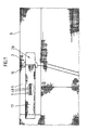
- the slide which is guided in a sled-like manner on a locking rail 1 assigned to the collar, has a folding lever 2 and a slide base plate 3 which supports it.
- the locking rail 1 has, mostly by a central sewing recess 4, transverse locking recesses 5.
- the rail base 6 is retracted. This retraction is undercut by double-angled guide tabs 7 cut out of the material of the slide plate 3.
- a seam 8 holds the locking rail 1 and thus the closure at one end A of the waistband 9th
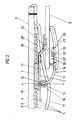
- the angular folding lever 2 has a shorter angle leg 10 and a longer angle leg 11. These angle legs are obtuse to each other.
- the folding axis is formed by two sections 12 ⁇ of a frame leg 12 of the shorter angle leg 10.
- the sections 12 ' lie in the bearing eyes 13 of the slide base plate 3.
- These bearing eyes 13 are formed by cut-free and essentially circular rolled-up edge tongues of the slide base plate 3.
- the longer angle leg 11 of the folding lever 1 has a window 16 which is located directly behind the shorter 10.
- the latter allows the free passage of a cover strip 17 arranged on the outside in front of the latching rail 1 and fastened to the collar 9 at both ends.
- the width of the window corresponds approximately to the width of the cover strip 17.
- the cover strip 17 is in turn dimensioned so wide that it covers not only the locking rail 1, but also essentially the slide base plate 3 and the window frame leg 12, withdrawn from view.
- This window frame leg 12 engages with his Middle section in the locking recesses 5 of the locking rail 1.
- it forms a nose 19 which tilts into the locking recesses 5 of the locking rail on this central section. Their width corresponds approximately to that of the locking rail 1.
- the nose 19 passes through an opening formed in the slide base plate 3 through the formation of the guide tabs 7.
- the window 16 is installed as deep as possible in the vicinity of the slide bottom plate 3. This leads to a relatively small cross-section of the frame leg 12 there. This in turn favors the resilience, so that this frame leg 12 briefly escapes into the free space formed by the window 16 when the shorter angle leg 10 passes over the dead center line xx (see FIG. 2) . This creates a soft closing process. On the other hand, the restoring force inherent in the material favors safe engagement with the locking rail 1.
- the slide base plate 3 is offset somewhat from the locking rail 1. This is done by cranking the slide base plate 3 twice at an obtuse angle.
- the offset area has a further window 28 for the passage of the cover strip 17, which thus also extends over the slide section lying behind the flange end B.
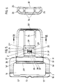
- the longer angle leg 11 of the folding lever 2 is equipped with a cover 20 fastened by means of the plug-in latching connection. It is a plastic injection-molded part in the form of a flat plate, like the angle leg 11, which is slightly curved in the direction of displacement of the slide. Their greatest width y (FIG. 5) is substantially larger than the width z of the longer angle leg 11 measured in this direction. As can be seen from FIG. 5, the cover 20 has about three times the width z of the longer angle leg 11.
- the plug-in latching connection is implemented in such a way that the free end of the longer angle leg forms a relatively small tongue Z, which fits into an insert pocket that is open toward the window 16 in a form-fitting manner.
- the means providing the latching connection are located on the broad surface of this tongue Z, in the form of a latching projection 31. The latter lies in the central region of the essentially square tongue Z.
- the latching projection 31 consists of a notch cut out on three sides and bent out in an S-shaped manner in the direction of the federal government 9, the front end of which extends parallel to the folding axis, i.e. the 31 ⁇ of the latching projection 31 blocking in front of the corresponding edge 32 ⁇ of an entry space 32 facing the latching rail 1 Pocket wall 33 occurs.
- the entry space 32 is realized in the form of a window-like wall opening.
- the back of the latching projection 31 facing away from the steep front end 31 ⁇ has a ramp slope 31 ⁇ which facilitates the plug-in latching assignment.
- Their angle of inclination to the plate or pocket level is approx. 30 °.
- the other pocket wall is practically formed by the plate-shaped body of the cover 20.
- the parallel pocket side walls 21 ⁇ continue, projecting beyond the pocket bottom 21 ⁇ , into longitudinal, web-like stabilizing ribs 34. They also run continuously parallel to one another and are rooted at the end in a web-like edge folding section 35 ⁇ of a circumferential edge folding 35. This edge folding stabilizes the relatively thin-walled cover 20.
- the stabilizing ribs 34, the edge folding section 35 ⁇ and the rest of the edge folding 35 running in the side region of the cover 20 are all of same height and assign closed collar closure all in the direction of the locking rail 1.
- the side edges of the cover 20 converge slightly towards the free end. Their corners are rounded convex.
- the pocket 21 is located in the region of the half of the cover 20 facing the window 16.
- the window-side end portion 20 ⁇ of the cover 20 engages in a bead-like manner in the cross-sectional area of the window 16, so that the window edge 15 ⁇ formed by the frame leg 15 of the window 16 there is overlapped by this end portion 20 ⁇ in a protective manner.
- the corresponding overlapping section of the cover is preferably cross-rounded there. This makes it possible to dispense with a special finish of this window edge; the cover strip 17 thereby receives increased wear protection.
- the frame leg 15 is also offset in a plane such that on the top of this frame leg 15 forming the window there is a recess 36 into which the section 20 ⁇ is full or only partially occurs.
- the corresponding window engagement also provides lateral support against pivoting of the cover 20 at the cut-away inside corner edges 16 ⁇ of the window 16.
- the edge fold 35 is interrupted in the region of the inserted end section 20 ⁇ . These interruptions are designated 37 (see FIG. 5).
- the wide pocket wall 33 continues into a freely projecting, canopy-like tab 38. Its front edge is cross-rounded and thus favors the self-centering insertion of the tongue Z during the snap-in process.
- the corresponding free space brings a greater degree of movement when the locking projection 31 passes underneath, since there is no corresponding transition connection on the pocket side walls 21 ⁇ , in other words: the pocket is cut back. The The bag is therefore not stretched excessively.
- the pocket-side root or base line of the freely projecting flap 38 runs approximately at the level of the window-side edge 32 ⁇ of the entry space 32.
- the dashed line shown in FIG. 5, designated 39 corresponds to this base line and at the same time indicates a wall thickness of the other that is slightly larger than the general panel thickness , from the plate of the cover 20 formed pocket wall, so that the pocket-forming zone is highly stable (see also Fig. 4).
- a release of the cover for example in order to change this application, is only possible with emphasis on reaching under the flap 38 which then acts as an opening aid, but with the cover end section 20 End being lifted out of the window at the same time, but after which the side cover is also lifted out Support on the inner corner edges 16 ⁇ of the window 16 is eliminated.
Landscapes
- Engineering & Computer Science (AREA)
- Textile Engineering (AREA)
- Details Of Garments (AREA)
- Buckles (AREA)
- Slide Fasteners (AREA)
- Insulating Bodies (AREA)
Applications Claiming Priority (2)
| Application Number | Priority Date | Filing Date | Title |
|---|---|---|---|
| DE3628771 | 1986-08-25 | ||
| DE19863628771 DE3628771A1 (de) | 1986-08-25 | 1986-08-25 | Verschluss fuer bunde oder dergleichen |
Publications (2)
| Publication Number | Publication Date |
|---|---|
| EP0261321A2 true EP0261321A2 (fr) | 1988-03-30 |
| EP0261321A3 EP0261321A3 (fr) | 1989-02-08 |
Family
ID=6308108
Family Applications (1)
| Application Number | Title | Priority Date | Filing Date |
|---|---|---|---|
| EP87109293A Withdrawn EP0261321A3 (fr) | 1986-08-25 | 1987-06-27 | Fermeture de ceinture ou analogue |
Country Status (4)
| Country | Link |
|---|---|
| US (1) | US4780939A (fr) |
| EP (1) | EP0261321A3 (fr) |
| JP (1) | JPS6359405A (fr) |
| DE (1) | DE3628771A1 (fr) |
Families Citing this family (13)
| Publication number | Priority date | Publication date | Assignee | Title |
|---|---|---|---|---|
| US4985520A (en) * | 1988-07-29 | 1991-01-15 | Asahi Kasei Kogyo Kabushiki Kaisha | Fluoroelastomer having excellent processability |
| JPH0613211Y2 (ja) * | 1989-04-26 | 1994-04-06 | モリト株式会社 | 衣服用腰回り調整装置 |
| US5023979A (en) * | 1989-12-06 | 1991-06-18 | Bennett Robert B | Fastener for garments |
| CA2037234A1 (fr) * | 1990-03-01 | 1991-09-02 | Dana P. Carlson | Elastomeres thermoplastiques fluores a stabilite accrue contre les bases |
| US5058519A (en) * | 1990-04-02 | 1991-10-22 | Collins Denny L | Emergency damage patch and method for boats or the like |
| DE4107435A1 (de) * | 1990-11-12 | 1992-05-14 | Schaeffer Gmbh | Bundverschluss |
| US5926927A (en) * | 1997-12-13 | 1999-07-27 | Winkler; Marvin | Enhanced adjustable slider buckle means |
| JP3360256B2 (ja) * | 1999-09-17 | 2002-12-24 | モリト株式会社 | 調節用鉤ホック |
| KR101060070B1 (ko) * | 2009-09-15 | 2011-08-29 | 박해오 | 허리둘레 조절구 및 그것이 구비된 바지 |
| JP6987740B2 (ja) | 2015-07-13 | 2022-01-05 | スリーエム イノベイティブ プロパティズ カンパニー | フッ素化ブロックコポリマー |
| EP3571247A4 (fr) | 2017-01-18 | 2020-11-11 | 3M Innovative Properties Company | Copolymères séquencés fluorés |
| US11267922B2 (en) | 2017-01-18 | 2022-03-08 | 3M Innovative Properties Company | Fluorinated block copolymers derived from nitrile cure-site monomers |
| US11337476B2 (en) * | 2017-12-14 | 2022-05-24 | Vans, Inc. | Waistband system for garments |
Family Cites Families (10)
| Publication number | Priority date | Publication date | Assignee | Title |
|---|---|---|---|---|
| DE136865C (fr) * | ||||
| US3113362A (en) * | 1961-11-06 | 1963-12-10 | Petruzziello Tonino | Catch for wrist bands and the like |
| BE685349A (fr) * | 1966-08-10 | 1967-02-10 | ||
| DE2202565C2 (de) * | 1972-01-20 | 1973-09-27 | P. & M. Hillringhaus Kg, 5600 Wuppertal | Taillen , Rock oder Hosenver schluß |
| DE2505432A1 (de) * | 1975-02-08 | 1976-08-19 | Gutos Metallschliessen | Gleitverschluss fuer hosenbunde |
| DE2745820C2 (de) * | 1977-10-12 | 1987-02-05 | P & M Hillringhaus KG, 5600 Wuppertal | Verschluß für Bunde oder dergleichen |
| US4466162A (en) * | 1981-10-29 | 1984-08-21 | Pogharian Mardig V | Jewelry clasp |
| DE3215470C2 (de) * | 1982-04-24 | 1984-02-23 | P & M Hillringhaus KG, 5600 Wuppertal | Verschluß für Bunde o.dgl. |
| DE3324657A1 (de) * | 1983-07-08 | 1985-01-17 | Schaeffer Scovill Verbindungstechnik GmbH, 5600 Wuppertal | Verschluss fuer bunde oder dergleichen |
| IT8409513U1 (it) * | 1984-05-08 | 1985-11-08 | Biavaschi Ciapusci Ilde | Ancoraggio di sicurezza ad arpione bloccabile per cinghia dentata di serraggio degli scarponi da sci |
-
1986
- 1986-08-25 DE DE19863628771 patent/DE3628771A1/de not_active Withdrawn
-
1987
- 1987-04-17 JP JP62093452A patent/JPS6359405A/ja active Pending
- 1987-06-27 EP EP87109293A patent/EP0261321A3/fr not_active Withdrawn
- 1987-08-05 US US07/082,826 patent/US4780939A/en not_active Expired - Fee Related
Also Published As
| Publication number | Publication date |
|---|---|
| EP0261321A3 (fr) | 1989-02-08 |
| JPS6359405A (ja) | 1988-03-15 |
| DE3628771A1 (de) | 1988-03-10 |
| US4780939A (en) | 1988-11-01 |
Similar Documents
| Publication | Publication Date | Title |
|---|---|---|
| LU85302A1 (de) | Behaeltnis fuer ein kosmetisches erzeugnis und verfahren zur benutzung des behaeltnisses | |
| DE3701293A1 (de) | Stapelbarer eckenschoner | |
| DE3145360A1 (de) | Klemmschnalle | |
| DE3628771A1 (de) | Verschluss fuer bunde oder dergleichen | |
| DE2751683B2 (de) | Sicht- bzw. Griffreiter aus Kunststoff zur Anbringung an der oberen Randkante von Hangeheftern oder Hängetaschen | |
| DE69505832T2 (de) | Anordnung mit einem nachfüllbaren kompakten blattspender | |
| DE4322669A1 (de) | Befestigungseinrichtung | |
| DE9112615U1 (de) | Behälterverschluß mit Schnappeffekt | |
| DE3603876A1 (de) | Halteklip fuer schreibgeraete | |
| EP0910971A2 (fr) | Clip pour téléphone mobile | |
| EP0053315A1 (fr) | Fermeture pour vêtements de dessus, en particulier pour vêtements de fourrure | |
| DE2745820C2 (de) | Verschluß für Bunde oder dergleichen | |
| EP4166039A1 (fr) | Paroi latérale de tiroir | |
| DE8708606U1 (de) | Verschluß für Bunde od.dgl. | |
| DE2518954A1 (de) | Griff fuer haushaltgeraete | |
| DE69707593T2 (de) | Tasche mit einem Verschluss | |
| DE3324657C2 (fr) | ||
| EP0212346B1 (fr) | Récipient pour documents | |
| DE3116331C2 (de) | Aufhängevorrichtung für Vorhänge oder dgl. | |
| DE2715017C3 (de) | Vorhangschienengleiter | |
| DE3341708A1 (de) | Kollektionsmappe | |
| DE2030525C3 (de) | Selbsttätiger Tubenverschluß | |
| DE2355614A1 (de) | Schieber fuer verdeckte reissverschluesse | |
| EP0088070A1 (fr) | Crampon | |
| DE9217203U1 (de) | Dokumentenmappe mit Heftklammer |
Legal Events
| Date | Code | Title | Description |
|---|---|---|---|
| PUAI | Public reference made under article 153(3) epc to a published international application that has entered the european phase |
Free format text: ORIGINAL CODE: 0009012 |
|
| AK | Designated contracting states |
Kind code of ref document: A2 Designated state(s): AT BE CH DE ES FR GB GR IT LI LU NL SE |
|
| RAP1 | Party data changed (applicant data changed or rights of an application transferred) |
Owner name: SCHAEFFER GMBH |
|
| PUAL | Search report despatched |
Free format text: ORIGINAL CODE: 0009013 |
|
| AK | Designated contracting states |
Kind code of ref document: A3 Designated state(s): AT BE CH DE ES FR GB GR IT LI LU NL SE |
|
| 17P | Request for examination filed |
Effective date: 19890322 |
|
| 17Q | First examination report despatched |
Effective date: 19900828 |
|
| STAA | Information on the status of an ep patent application or granted ep patent |
Free format text: STATUS: THE APPLICATION IS DEEMED TO BE WITHDRAWN |
|
| 18D | Application deemed to be withdrawn |
Effective date: 19901225 |
|
| RIN1 | Information on inventor provided before grant (corrected) |
Inventor name: BELTER, LOTHAR Inventor name: CHRISTIANS, GUSTAV Inventor name: KLINGENBURG, ERICH |