EP0261376B1 - Dispositif d'accélération de grenaille magnétique - Google Patents
Dispositif d'accélération de grenaille magnétique Download PDFInfo
- Publication number
- EP0261376B1 EP0261376B1 EP87111743A EP87111743A EP0261376B1 EP 0261376 B1 EP0261376 B1 EP 0261376B1 EP 87111743 A EP87111743 A EP 87111743A EP 87111743 A EP87111743 A EP 87111743A EP 0261376 B1 EP0261376 B1 EP 0261376B1
- Authority
- EP
- European Patent Office
- Prior art keywords
- coil
- concentrator
- accelerating
- blasting
- blasting abrasive
- Prior art date
- Legal status (The legal status is an assumption and is not a legal conclusion. Google has not performed a legal analysis and makes no representation as to the accuracy of the status listed.)
- Expired - Lifetime
Links
- 238000005422 blasting Methods 0.000 title claims description 29
- 239000000463 material Substances 0.000 title claims description 3
- 230000001133 acceleration Effects 0.000 claims description 12
- 238000004804 winding Methods 0.000 claims description 10
- XEEYBQQBJWHFJM-UHFFFAOYSA-N Iron Chemical compound [Fe] XEEYBQQBJWHFJM-UHFFFAOYSA-N 0.000 claims description 4
- 239000002245 particle Substances 0.000 claims description 4
- 238000011144 upstream manufacturing Methods 0.000 claims description 3
- 229910052742 iron Inorganic materials 0.000 claims description 2
- 230000004907 flux Effects 0.000 description 16
- 239000003795 chemical substances by application Substances 0.000 description 11
- 238000010586 diagram Methods 0.000 description 7
- 230000006698 induction Effects 0.000 description 7
- 230000005284 excitation Effects 0.000 description 6
- 239000004020 conductor Substances 0.000 description 2
- 239000004604 Blowing Agent Substances 0.000 description 1
- RYGMFSIKBFXOCR-UHFFFAOYSA-N Copper Chemical compound [Cu] RYGMFSIKBFXOCR-UHFFFAOYSA-N 0.000 description 1
- 108010066114 cabin-2 Proteins 0.000 description 1
- 239000003990 capacitor Substances 0.000 description 1
- 238000010276 construction Methods 0.000 description 1
- 229910052802 copper Inorganic materials 0.000 description 1
- 239000010949 copper Substances 0.000 description 1
- 230000001419 dependent effect Effects 0.000 description 1
- 230000000694 effects Effects 0.000 description 1
- 238000000034 method Methods 0.000 description 1
- 230000000737 periodic effect Effects 0.000 description 1
- 238000004381 surface treatment Methods 0.000 description 1
Images



Classifications
-
- F—MECHANICAL ENGINEERING; LIGHTING; HEATING; WEAPONS; BLASTING
- F41—WEAPONS
- F41B—WEAPONS FOR PROJECTING MISSILES WITHOUT USE OF EXPLOSIVE OR COMBUSTIBLE PROPELLANT CHARGE; WEAPONS NOT OTHERWISE PROVIDED FOR
- F41B6/00—Electromagnetic launchers ; Plasma-actuated launchers
-
- B—PERFORMING OPERATIONS; TRANSPORTING
- B24—GRINDING; POLISHING
- B24C—ABRASIVE OR RELATED BLASTING WITH PARTICULATE MATERIAL
- B24C5/00—Devices or accessories for generating abrasive blasts
- B24C5/08—Devices for generating abrasive blasts non-mechanically, e.g. of metallic abrasives by means of a magnetic field or by detonating cords
Definitions
- the invention relates to a device for accelerating a blasting medium consisting of particles which can be influenced magnetically, in particular iron particles, for treating workpiece surfaces with one or more electromagnetic accelerator coils (s) arranged along the path of the blasting medium which excite or excite depending on the moving blasting medium will.
- a device for accelerating a blasting medium consisting of particles which can be influenced magnetically, in particular iron particles, for treating workpiece surfaces with one or more electromagnetic accelerator coils (s) arranged along the path of the blasting medium which excite or excite depending on the moving blasting medium will.
- the invention is based on the object of creating a device of the type mentioned at the outset, i.e. to create a device in which the blasting medium is accelerated with the aid of the magnetic force generated in an accelerator coil and thereby manages with a lower energy requirement compared to conventional types of acceleration with equivalent performance (throughput quantity of blasting medium per unit time).
- Flow concentrators of this type have hitherto been used in completely different fields, in particular in basic research. These flux concentrators have a core made of electrically highly conductive material, e.g. made of copper, in which there is a usable field bore and a radial slot. If a winding which is located on the outside of the core is now flowed through by a pulsed current, then a current is induced in the opposite direction into the electrically well-conducting core according to the transformer principle and flows as a pulse current only on the surface of the core. At the location of the radial slot, the current flow is forced inwards around the useful field bore.
- electrically highly conductive material e.g. made of copper
- abrasive device which is basically constructed in the same way as conventional abrasive devices. It consists of an electromagnetic acceleration unit 1, the heart of which is a flux concentrator. A movable blasting hose 3 is arranged in the blasting agent cabin 2, by means of which an operator can direct the accelerated blasting agent onto a workpiece 4. The blasting agent return and feed is designated by 5.
- the acceleration unit shown in Fig. 2 consists of a flux concentrator 6 as an accelerator coil.
- the blasting agent 9 is fed via a feed device 8.
- a metering coil 7 serves as a “pre-bundler” through which the abrasive is distributed in the desired amount to the flux concentrator 6.
- the blasting agent outlet is designated by 10.
- On this Exit is the jet hose 3 recognizable in Fig. 1 placed.
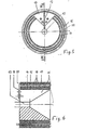
- the essentially rotationally symmetrical flow concentrator shown in FIG. 4 practically as a section perpendicular to the axis of the movement of the blasting medium has a core 11 constructed from a material which is a good electrical conductor (e.g. copper) and in which a cylindrical useful field bore 12 and a radial slot 13 are provided.
- the excitation winding which can consist of several turns, is designated by 14.
- FIG. 5 and 6 another advantageous embodiment is shown.
- two excitation windings 14 and 15 are nested concentrically with corresponding concentrator cores.
- the inner part corresponds to that according to FIG. 4 and is designated with corresponding reference numerals.
- a concentrator shell 18 is placed on this inner part, which acts as an additional core for the outer field winding 15. The two arrangements add up in their effect.
- the concentrator shell 18 is connected to the inner core 11 at 19.
- FIG. 7 shows the circuit diagram of a pulse generator working with thyristors Ti, T 2 , with which a system constructed according to FIGS. 5 and 6 was tested.
- the voltage source with the voltage UO charges the capacitor C L , which is periodically discharged via the thyristors Ti, T 2 acting in parallel as controllable switches into the load inductance L L of the flux concentrator (inductance of the excitation coils) and, due to the pulse-shaped current flow thus created, the desired one there Effective field with induction B.
- FIG. 8 shows a curve of the induction B over the axis of the flux concentrator obtained with a concentrator construction according to FIGS. 5 and 6 and a pulse generator according to FIG. 7.
- the dimensions given in millimeters correspond to an embodiment that has been tried and tested in practice.
- two excitation windings with ten windings each with a current of 10,000 A were operated.
- the turns of the excitation windings were directly water-cooled.
- the power loss is approx. 5 kW.
- the accelerator unit shown in Fig. 2 works so that the metering coil 7 is briefly de-energized (see also the upper timing diagram in Fig. 3), so that the induction B of this metering coil also disappears. The abrasive is released and starts to move. If the magnetic flux concentrator 6 acting as an accelerator is excited at the same time (see also the lower time diagram in FIG. 3), a strong acceleration of the blasting agent will start under the influence of the much higher induction B of the flux concentrator. This is only effective during the pulse duration in the accelerator coil. This pulse duration must be set so that the pulse ends when the blasting agent emerges from the flow concentrator.
- a measuring coil can be used, which is arranged between the coils 6 and 7 in the embodiment according to FIG. 2.
- This measuring coil detects incoming blasting media as an electrical signal in order to ignite a current pulse in the accelerator coil following in the direction of movement (designated 6 in FIG. 2). This enables particularly economical and precise control.
Landscapes
- Engineering & Computer Science (AREA)
- Mechanical Engineering (AREA)
- Physics & Mathematics (AREA)
- Electromagnetism (AREA)
- Plasma & Fusion (AREA)
- General Engineering & Computer Science (AREA)
- Particle Accelerators (AREA)
Claims (4)
Applications Claiming Priority (2)
| Application Number | Priority Date | Filing Date | Title |
|---|---|---|---|
| DE3629255 | 1986-08-28 | ||
| DE3629255A DE3629255C1 (de) | 1986-08-28 | 1986-08-28 | Vorrichtung zum Beschleunigen von magnetisch beeinflussbarem Strahlmittel |
Publications (3)
| Publication Number | Publication Date |
|---|---|
| EP0261376A2 EP0261376A2 (fr) | 1988-03-30 |
| EP0261376A3 EP0261376A3 (en) | 1989-01-18 |
| EP0261376B1 true EP0261376B1 (fr) | 1990-06-13 |
Family
ID=6308362
Family Applications (1)
| Application Number | Title | Priority Date | Filing Date |
|---|---|---|---|
| EP87111743A Expired - Lifetime EP0261376B1 (fr) | 1986-08-28 | 1987-08-13 | Dispositif d'accélération de grenaille magnétique |
Country Status (2)
| Country | Link |
|---|---|
| EP (1) | EP0261376B1 (fr) |
| DE (2) | DE3629255C1 (fr) |
Families Citing this family (5)
| Publication number | Priority date | Publication date | Assignee | Title |
|---|---|---|---|---|
| FR2698576B1 (fr) * | 1992-11-30 | 1995-02-17 | Framatome Sa | Procédé et dispositif de réparation d'une zone défectueuse de la paroi d'une pièce métallique et en particulier d'une pièce tubulaire. |
| US6561874B1 (en) * | 2000-11-22 | 2003-05-13 | Qed Technologies, Inc | Apparatus and method for abrasive jet finishing of deeply concave surfaces using magnetorheological fluid |
| SG10201602833VA (en) * | 2016-04-11 | 2017-11-29 | Abrasive Eng Pte Ltd | Magnetic Valve for Shot Peening |
| TWI790473B (zh) * | 2020-08-28 | 2023-01-21 | 態金材料科技股份有限公司 | 以金屬玻璃粒子束切割之方法 |
| JP7485588B2 (ja) * | 2020-11-25 | 2024-05-16 | 株式会社日本製鋼所 | 射出装置 |
Family Cites Families (4)
| Publication number | Priority date | Publication date | Assignee | Title |
|---|---|---|---|---|
| US754637A (en) * | 1902-06-25 | 1904-03-15 | Kristian Birkeland | Electromagnetic gun. |
| CH240861A (de) * | 1944-06-17 | 1946-01-31 | Bbc Brown Boveri & Cie | Einrichtung zur Erzeugung eines Eisenschrotstrahles hoher Geschwindigkeit. |
| GB1084496A (en) * | 1965-06-15 | 1967-09-20 | British Steel Castings Res Ass | Improved method of and equipment for shot-blasting and the like |
| DE3324710C1 (de) * | 1983-07-08 | 1984-05-30 | Jost Dipl.-Ing. 2150 Buxtehude Wadephul | Vorrichtung zum Beschleunigen von Strahlmittel |
-
1986
- 1986-08-28 DE DE3629255A patent/DE3629255C1/de not_active Expired
-
1987
- 1987-08-13 DE DE8787111743T patent/DE3763157D1/de not_active Expired - Fee Related
- 1987-08-13 EP EP87111743A patent/EP0261376B1/fr not_active Expired - Lifetime
Also Published As
| Publication number | Publication date |
|---|---|
| DE3763157D1 (de) | 1990-07-19 |
| EP0261376A2 (fr) | 1988-03-30 |
| EP0261376A3 (en) | 1989-01-18 |
| DE3629255C1 (de) | 1987-04-02 |
Similar Documents
| Publication | Publication Date | Title |
|---|---|---|
| DE3427920C2 (fr) | ||
| EP0454183A1 (fr) | Moteur électrique rotatif | |
| DE3639256A1 (de) | Impulsgenerator zur funkenerosiven metallberarbeitung | |
| DE2159369C3 (de) | Schaltungsanordnung zum Einschalten und Ausschalten einer Induktivität | |
| EP0097773A1 (fr) | Aimant de levage avec dispositif de détection | |
| DE676128C (de) | Einrichtung zur Ausloesung von Schalt- oder Steuerimpulsen zu einem innerhalb einer Periode einer Wechselspannung waehlbaren Zeitpunkt | |
| EP0261376B1 (fr) | Dispositif d'accélération de grenaille magnétique | |
| DE1246138B (de) | Schaltanordnung zur Durchfuehrung eines Verfahrens zum Erzeugen, Beschleunigen und/oder dynamischen Einschliessen von Plasmoiden | |
| DE2912404C2 (de) | Schaltungsanordnung zur Reinigung eines Kontaktes | |
| EP0018352B1 (fr) | Dispositif ou machine électrique | |
| DE4122601A1 (de) | Linearbeschleuniger | |
| DE924699C (de) | Vorrichtung mit einem durch Impulse zu erregenden Magnetron | |
| CH693088A5 (de) | Funkenerosionsmaschine. | |
| DE2501858C2 (de) | Vorrichtung zum Abscheiden magnetisierbarer Teilchen, die in einer Flüssigkeit suspendiert sind | |
| DE2256521A1 (de) | Vorrichtung zum steuern des erregerstroms einer einen magnetfluss mit umkehrbarer richtung erzeugenden spule | |
| DE3136676C2 (de) | Steuerschaltung für eine elektromagnetische Kochvorrichtung | |
| DE2019933A1 (de) | Anordnung zum Gleichrichten einer pulsfoermigen Wechselspannung | |
| DE3326582C2 (fr) | ||
| DE3008562C2 (de) | Magnetischer Näherungsschalter | |
| DE3238609A1 (de) | Entmagnetisierungseinrichtung | |
| DE666978C (de) | Differentialschutzeinrichtung fuer Apparate und Maschinen | |
| DE2530436C3 (de) | Einrichtung zur Plasmabearbeitung von Metallen | |
| DE1589889C3 (de) | Verfahren und Anordnungen zur kontinuierlichen Entmagnetisierung von ferromagnetischen Halb- oder Fertigfabrikaten bei Anwesenheit magnetischer Störfelder | |
| AT250450B (de) | Schaltungsanordnung, insbesondere für Koppelfeldschalter | |
| DE1538703A1 (de) | Gleichstrommaschine |
Legal Events
| Date | Code | Title | Description |
|---|---|---|---|
| PUAI | Public reference made under article 153(3) epc to a published international application that has entered the european phase |
Free format text: ORIGINAL CODE: 0009012 |
|
| AK | Designated contracting states |
Kind code of ref document: A2 Designated state(s): BE CH DE ES FR GB IT LI NL |
|
| PUAL | Search report despatched |
Free format text: ORIGINAL CODE: 0009013 |
|
| AK | Designated contracting states |
Kind code of ref document: A3 Designated state(s): BE CH DE ES FR GB IT LI NL |
|
| 17P | Request for examination filed |
Effective date: 19890425 |
|
| 17Q | First examination report despatched |
Effective date: 19890929 |
|
| GRAA | (expected) grant |
Free format text: ORIGINAL CODE: 0009210 |
|
| AK | Designated contracting states |
Kind code of ref document: B1 Designated state(s): BE CH DE ES FR GB IT LI NL |
|
| PG25 | Lapsed in a contracting state [announced via postgrant information from national office to epo] |
Ref country code: IT Free format text: LAPSE BECAUSE OF FAILURE TO SUBMIT A TRANSLATION OF THE DESCRIPTION OR TO PAY THE FEE WITHIN THE PRE;WARNING: LAPSES OF ITALIAN PATENTS WITH EFFECTIVE DATE BEFORE 2007 MAY HAVE OCCURRED AT ANY TIME BEFORE 2007. THE CORRECT EFFECTIVE DATE MAY BE DIFFERENT FROM THE ONE RECORDED.SCRIBED TIME-LIMIT Effective date: 19900613 Ref country code: NL Effective date: 19900613 Ref country code: BE Effective date: 19900613 Ref country code: GB Effective date: 19900613 |
|
| REF | Corresponds to: |
Ref document number: 3763157 Country of ref document: DE Date of ref document: 19900719 |
|
| ET | Fr: translation filed | ||
| PG25 | Lapsed in a contracting state [announced via postgrant information from national office to epo] |
Ref country code: ES Free format text: LAPSE BECAUSE OF FAILURE TO SUBMIT A TRANSLATION OF THE DESCRIPTION OR TO PAY THE FEE WITHIN THE PRESCRIBED TIME-LIMIT Effective date: 19900924 |
|
| NLV1 | Nl: lapsed or annulled due to failure to fulfill the requirements of art. 29p and 29m of the patents act | ||
| GBV | Gb: ep patent (uk) treated as always having been void in accordance with gb section 77(7)/1977 [no translation filed] | ||
| PLBE | No opposition filed within time limit |
Free format text: ORIGINAL CODE: 0009261 |
|
| STAA | Information on the status of an ep patent application or granted ep patent |
Free format text: STATUS: NO OPPOSITION FILED WITHIN TIME LIMIT |
|
| RAP2 | Party data changed (patent owner data changed or rights of a patent transferred) |
Owner name: ALFRED GUTMANN GESELLSCHAFT FUER MASCHINENBAU MBH |
|
| 26N | No opposition filed | ||
| REG | Reference to a national code |
Ref country code: CH Ref legal event code: PUE Owner name: ALFRED GUTMANN GESELLSCHAFT FUER MASCHINENBAU MBH |
|
| PGFP | Annual fee paid to national office [announced via postgrant information from national office to epo] |
Ref country code: DE Payment date: 19970723 Year of fee payment: 11 |
|
| PGFP | Annual fee paid to national office [announced via postgrant information from national office to epo] |
Ref country code: FR Payment date: 19970818 Year of fee payment: 11 |
|
| PGFP | Annual fee paid to national office [announced via postgrant information from national office to epo] |
Ref country code: CH Payment date: 19970827 Year of fee payment: 11 |
|
| PG25 | Lapsed in a contracting state [announced via postgrant information from national office to epo] |
Ref country code: CH Free format text: LAPSE BECAUSE OF NON-PAYMENT OF DUE FEES Effective date: 19980831 Ref country code: LI Free format text: LAPSE BECAUSE OF NON-PAYMENT OF DUE FEES Effective date: 19980831 |
|
| REG | Reference to a national code |
Ref country code: CH Ref legal event code: PL |
|
| PG25 | Lapsed in a contracting state [announced via postgrant information from national office to epo] |
Ref country code: FR Free format text: LAPSE BECAUSE OF NON-PAYMENT OF DUE FEES Effective date: 19990430 |
|
| PG25 | Lapsed in a contracting state [announced via postgrant information from national office to epo] |
Ref country code: DE Free format text: LAPSE BECAUSE OF NON-PAYMENT OF DUE FEES Effective date: 19990601 |
|
| REG | Reference to a national code |
Ref country code: FR Ref legal event code: ST |