EP0261393A2 - Akustischer Oberflächenwellen-Gasdurchflussgeschwindigkeitssensor mit Selbstheizungszusatz - Google Patents
Akustischer Oberflächenwellen-Gasdurchflussgeschwindigkeitssensor mit Selbstheizungszusatz Download PDFInfo
- Publication number
- EP0261393A2 EP0261393A2 EP87111994A EP87111994A EP0261393A2 EP 0261393 A2 EP0261393 A2 EP 0261393A2 EP 87111994 A EP87111994 A EP 87111994A EP 87111994 A EP87111994 A EP 87111994A EP 0261393 A2 EP0261393 A2 EP 0261393A2
- Authority
- EP
- European Patent Office
- Prior art keywords
- region
- temperature
- flow rate
- gas
- increasing
- Prior art date
- Legal status (The legal status is an assumption and is not a legal conclusion. Google has not performed a legal analysis and makes no representation as to the accuracy of the status listed.)
- Withdrawn
Links
Images

Classifications
-
- G—PHYSICS
- G01—MEASURING; TESTING
- G01F—MEASURING VOLUME, VOLUME FLOW, MASS FLOW OR LIQUID LEVEL; METERING BY VOLUME
- G01F1/00—Measuring the volume flow or mass flow of fluid or fluent solid material wherein the fluid passes through a meter in a continuous flow
- G01F1/68—Measuring the volume flow or mass flow of fluid or fluent solid material wherein the fluid passes through a meter in a continuous flow by using thermal effects
-
- G—PHYSICS
- G01—MEASURING; TESTING
- G01F—MEASURING VOLUME, VOLUME FLOW, MASS FLOW OR LIQUID LEVEL; METERING BY VOLUME
- G01F1/00—Measuring the volume flow or mass flow of fluid or fluent solid material wherein the fluid passes through a meter in a continuous flow
- G01F1/66—Measuring the volume flow or mass flow of fluid or fluent solid material wherein the fluid passes through a meter in a continuous flow by measuring frequency, phase shift or propagation time of electromagnetic or other waves, e.g. using ultrasonic flowmeters
-
- G—PHYSICS
- G01—MEASURING; TESTING
- G01F—MEASURING VOLUME, VOLUME FLOW, MASS FLOW OR LIQUID LEVEL; METERING BY VOLUME
- G01F1/00—Measuring the volume flow or mass flow of fluid or fluent solid material wherein the fluid passes through a meter in a continuous flow
- G01F1/68—Measuring the volume flow or mass flow of fluid or fluent solid material wherein the fluid passes through a meter in a continuous flow by using thermal effects
- G01F1/684—Structural arrangements; Mounting of elements, e.g. in relation to fluid flow
- G01F1/688—Structural arrangements; Mounting of elements, e.g. in relation to fluid flow using a particular type of heating, cooling or sensing element
- G01F1/6882—Structural arrangements; Mounting of elements, e.g. in relation to fluid flow using a particular type of heating, cooling or sensing element making use of temperature dependence of acoustic properties, e.g. propagation speed of surface acoustic waves
-
- G—PHYSICS
- G01—MEASURING; TESTING
- G01N—INVESTIGATING OR ANALYSING MATERIALS BY DETERMINING THEIR CHEMICAL OR PHYSICAL PROPERTIES
- G01N2291/00—Indexing codes associated with group G01N29/00
- G01N2291/02—Indexing codes associated with the analysed material
- G01N2291/028—Material parameters
- G01N2291/02836—Flow rate, liquid level
-
- Y—GENERAL TAGGING OF NEW TECHNOLOGICAL DEVELOPMENTS; GENERAL TAGGING OF CROSS-SECTIONAL TECHNOLOGIES SPANNING OVER SEVERAL SECTIONS OF THE IPC; TECHNICAL SUBJECTS COVERED BY FORMER USPC CROSS-REFERENCE ART COLLECTIONS [XRACs] AND DIGESTS
- Y10—TECHNICAL SUBJECTS COVERED BY FORMER USPC
- Y10S—TECHNICAL SUBJECTS COVERED BY FORMER USPC CROSS-REFERENCE ART COLLECTIONS [XRACs] AND DIGESTS
- Y10S73/00—Measuring and testing
- Y10S73/04—Piezoelectric
Definitions
- This invention relates generally to sensors and, more particularly, to a surface acoustic wave gas flow rate sensor with a self-heating capability.
- Gas flow rate sensors are widely used for detecting the mass flow rate of a gas through a confined duct.
- one application for such sensors is in process controls, an aspect of which includes the control of heating, ventilating and air conditioning (HVAC) control systems where it is often desirable to continuously monitor and control the rate of flow of air through a particular duct.
- HVAC heating, ventilating and air conditioning
- One known approach to the detection and transduction of the mass flow rate of a gas involves the use of a plurality of temperature coefficient thermistors disposed in a regular, spaced-apart relationship within a duct and in an orientation to define a plane which is normal to the axis of flow of the gas. Support is typically by a lattice of wires supported horizontally and vertically across the passage to define a grid. With a known voltage applied to each thermistor having a known temperature coefficient characteristic, the resulting temperature rise over that of surrounding quiescent gas is also known.
- the mass flow rate may be determined by detecting the change in thermistor temperature, as evidenced by changes in thermistor current or voltage, from that which existed in the quiescent state.
- the apparatus described therein comprises a surface acoustic wave (SAW) flow sensor which incorporates a separate resistive element embodied as a thin film heater which operates to raise the temperature of the SAW substrate.
- the heater is energized by a separate voltage source and a flow of gas thereacross will lower the temperature of the substrate resulting in a detectable change in the frequency of the SAW delay line oscillator. This change in frequency may then be used to compute the mass flow rate.
- SAW surface acoustic wave
- an SAW sensor may be constructed to be self heating solely by the radio frequency (RF) signal which is applied to the delay line, thereby avoiding the necessity of a separate heater strip and related power source.
- RF radio frequency
- the substrate has disposed thereon a transmitting and a receiving interdigital transducer, the transducers being configured to have an operating frequency in the range of from 10MHz to 1000MHz. That portion of the substrate surface located between the transducers defines a propagation region and has a medium deposited thereon for absorbing a portion of the acoustical and/or electrical energy flowing thereacross. This absorbed energy increases the temperature of the propagation region over that of the surrounding ambient.
- a mass flow of the gas across the sensor will decrease its temperature and result in an upward shift in the resonant frequency.
- a suitable amplifier and resonant frequency detector may be coupled to the sensor for detecting the change in resonant frequency, thereby permitting mass flow rate measurement.
- Another object of the invention is to provide an SAW device which uses heat transfer characteristics to determine the mass flow rate of a gas.
- Still another object of the invention is to provide an SAW device which is self-heating.
- Yet another object of the invention is to provide an SAW device wherein its temperature rise is solely a result of the application of an RF signal thereto. How these and other objects are accomplished will become more apparent from the following detailed description thereof taken in conjunction with the drawing.
- the sensor 10 is shown in conjunction with an RF amplifier 11, an attenuator 13 and a frequency counter 15, the purposes of which will be described hereinafter.
- the sensor 10 includes a piezoelectric substrate 17 having disposed thereon a first, transmitting interdigital transducer 21 for generating a surface acoustical wave upon the substrate 17 and a second, receiving interdigital transducer 19 for detecting the surface wave and converting it to an RF signal.
- the material from which the substrate 17 is made, its crystallographic orientation and the geometry and orientation of the transducers 19, 21 can be selected to give a resonant frequency F o , a delay time T d , a temperature coefficient of delay (TCD) or temperature coefficient of frequency (TCF), a frequency bandwidth and an insertion loss that may all be well controlled.
- a thin film 23 of an energy absorbing medium is disposed on the substrate 17 in a propagation region 25 intermediate the transducers 19, 21 for coupling energy from the surface of the substrate 17, thereby generating heat.
- the heat so generated will elevate the temperature of the sensor 10 over that of the surrounding ambient gas in a quiescent state while a mass flow of the gas across the sensor 10 will decrease its temperature and result in a shift in the resonant frequency which is measurable and convertible to mass flow rate.
- the substrate 17 may be made of or overlaid with a piezoelectric material selected in accordance with the desired parameters of the application. Set forth below is a tabular listing of the approximate temperature coefficients of a few piezoelectric materials together with their crystallographic orientation.
- an exemplary substrate 17 was made of 128° rotated Y-cut, X-propagating LiNbO3 and had overall dimensions of approximately 10mm. in length, 20mm. in width and 0.5mm. in thickness.
- the top surface 27 thereof was highly polished in preparation for the deposition of the transducers 19, 21 and the film 23 thereon and a suitable substrate 17 is commercially available from several suppliers.
- the transducers 19, 21 may be of any one of a variety of materials including aluminum or nickel and may be formed by vacuum deposition upon the substrate 17 and subsequently etched to the desired geometry using known photolithographic techniques.
- the inventive sensor 10 is shown in conjunction with an RF oscillator 31 and a signal detector 33 in addition to the amplifier 11, attenuator 13 and frequency counter 15 illustrated in FIGURE 1, the purposes of which will be described hereinafter.
- each of the transducers 19, 21 is shown to include a first interdigital electrode 35 and a second interdigital electrode 37 and while the view of FIGURE 3 has been simplified, each electrode 35, 37 was configured to have fifteen fingers 39.
- D the propagation distance
- V a the acoustical velocity of propagation in meters per second
- T d is in seconds.
- L was selected to be 52.5 micrometers
- the aperture width W was selected to be 3.5mm
- D was selected to be 4.5mm
- N was selected to be 15 electrode pairs which resulted in a sensor 10 having a nominal resonant frequency of 75MHz and a 6dB bandwidth of 4.8MHz.
- a suitable thin film 23 may be formed of any material which may exist in solid phase at the ambient temperature of the environment and which is capable of being deposited in the aforementioned propagation region 25 in thicknesses ranging from nominally about 1% to 10% of the acoustical wavelength L.
- a preferred material will also be capable of absorbing energy from the substrate surface 27, i.e., from the mechanical Rayleigh wave propagating thereacross and/or from the electric field associated with this wave and due to piezoelectric property of the substrate 17, thereby providing self-heating.
- nickel-chromium alloy which may be deposited in the propagation region 25 by evaporation or sputtering.
- energy absorption will primarily be due to coupling with the electric field.
- a nonconductive polymer such as poly(methylmethacrylate) which will result in energy coupling primarily due to the mechanical wave.
- conductive polymers such as cermets and composite microwave absorbers such as iron in a methacrylate or epoxy matrix. Deposition may be by spraying, spincoating, chemical vapor deposition, painting or solution application.
- FIGURE 1 After having made a sensor 10 in accordance with the teachings of this specification, it may be connected in a circuit as generally shown in FIGURE 1 which includes the sensor 10, a 50 ohm variable attenuator 13, a broadband amplifier 11 and a signal detector 15 such as a digital frequency counter.
- a DC power of 15 volts at 150mA was applied to the amplifier 11 and with the attenuator 13 set at 1dB, the circuit oscillated at about 72.4MHz with a peak-to-peak amplitude of 1.25 volts.
- the temperature of the sensor 10 rose from an ambient of 23.8° C. to 24.0° C., the latter being the stabilized elevated temperature.
- the oscillation frequency varied by 3kHz corresponding to a flow variation of between 0 and 690ml per minute.
- a DC voltage of 20 volts was applied to the amplifier 11 and the attenuator 13 set at 1dB.
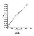
- the circuit oscillated at about 72.4MHz with an amplitude of 4 volts peak-to-peak and the sensor temperature rose from an ambient of 23.8° C. to a steady state elevated temperature of 24.6° C.
- the oscillation frequency varied by 10.3kHz for a mass flow variation ranging from 38 to 846ml per minute. It will also be appreciated that the change in resonant frequency resulting from the change in flow was substantially linear across the selected flow range.
- an RF oscillator 31 or signal generator and a signal detector 33 are additionally employed with the circuit of FIGURE 1.
- the oscillator 31 provides a signal at the nominal resonant frequency of the sensor 10 and the signal detector 33 measures the shift in phase between the signal applied at the first, transmitting interdigital transducer 21 and that received at the second, receiving interdigital transducer 19.
- the variation in magnitude of this phase shift will likewise permit computation of mass flow rate.
- Yet another approach to the determination of mass flow rates is by the detection of the time delay and changes therein between the time of application of a signal at the transmitting interdigital transducer 21 and its arrival at the receiving interdigital transducer 19.
- FIGURE 1 is the simpler and is significantly less expensive in its implementation. It is also to be appreciated that changes in resonant frequency as measured using the arrangement of FIGURE 1 and changes in phase as measured using that of FIGURE 2 are solely due to changes in temperature of the self-heating propagation region 25 which result from changes in the mass flow rate of the gas flowing thereacross.
- a sensor 10 may configure to have a resonant frequency in the range of 10MHz-1000MHz, this representing the nominal practical range available using known fabrication techniques although the selection of higher resonant design frequencies will likely be attended by increased difficulties in fabrication of the sensor 10.
- One factor which may govern the resonant frequency selected is that intrinsic temperature sensitivity, in change in resonant frequency per degree change in the temperature of the surface, increases with increasing resonant frequency.
- temperature rise by self-heating of the propagation region 25 is generally governed by the formula delta T 1/A where A is the area of the propagation region 25; that is, for a given sensor 10 and input power level, the temperature of the region 25 and the sensitivity of the sensor 10 both increase with decreases in A. Additionally, selection of higher design resonant frequencies indicate a decrease in the area A to maintain a given temperature rise.
- Similar structures may be used for the determination of mass flow rate using the teaching of the specification, such structures including the use of a piezoelectric polymer to form a propagation region 25 upon a nonpiezoelectric substrate.
- Another structure could employ a selective thinning of the propagation region 25, thereby permitting the excitation of measurable Lamb waves.
- One may also use bulk wave crystal oscillators in a self-heating mode or surface acoustical wave resonators.
Landscapes
- Physics & Mathematics (AREA)
- Fluid Mechanics (AREA)
- General Physics & Mathematics (AREA)
- Electromagnetism (AREA)
- Investigating Or Analyzing Materials By The Use Of Ultrasonic Waves (AREA)
- Measuring Volume Flow (AREA)
- Measurement Of Mechanical Vibrations Or Ultrasonic Waves (AREA)
Applications Claiming Priority (2)
| Application Number | Priority Date | Filing Date | Title |
|---|---|---|---|
| US899439 | 1986-08-22 | ||
| US06/899,439 US4726225A (en) | 1986-08-22 | 1986-08-22 | Surface acoustic wave gas flow rate sensor with self-heating feature |
Publications (2)
| Publication Number | Publication Date |
|---|---|
| EP0261393A2 true EP0261393A2 (de) | 1988-03-30 |
| EP0261393A3 EP0261393A3 (de) | 1990-03-14 |
Family
ID=25410975
Family Applications (1)
| Application Number | Title | Priority Date | Filing Date |
|---|---|---|---|
| EP87111994A Withdrawn EP0261393A3 (de) | 1986-08-22 | 1987-08-18 | Akustischer Oberflächenwellen-Gasdurchflussgeschwindigkeitssensor mit Selbstheizungszusatz |
Country Status (8)
| Country | Link |
|---|---|
| US (1) | US4726225A (de) |
| EP (1) | EP0261393A3 (de) |
| JP (1) | JPS6353422A (de) |
| KR (1) | KR880003171A (de) |
| AU (1) | AU598847B2 (de) |
| CA (1) | CA1286392C (de) |
| DK (1) | DK438387A (de) |
| NO (1) | NO873542L (de) |
Cited By (3)
| Publication number | Priority date | Publication date | Assignee | Title |
|---|---|---|---|---|
| US5872806A (en) * | 1995-08-10 | 1999-02-16 | Enderlein; Janos | Spread spectrum signal transmission method and system and also transmitter and receiver for use with the method and system |
| WO2005106401A1 (en) * | 2004-04-21 | 2005-11-10 | Honeywell International Inc. | Passive and wireless in-vivo acoustic wave flow sensor |
| WO2006098957A1 (en) * | 2005-03-09 | 2006-09-21 | Honeywell International Inc. | Low cost sh-saw fluid flow sensor |
Families Citing this family (21)
| Publication number | Priority date | Publication date | Assignee | Title |
|---|---|---|---|---|
| US5117146A (en) * | 1988-04-29 | 1992-05-26 | The United States Of America As Represented By The United States Department Of Energy | Acoustic wave device using plate modes with surface-parallel displacement |
| US4947677A (en) * | 1988-10-05 | 1990-08-14 | The United States Of America As Represented By The United States Department Of Energy | SAW determination of surface area of thin films |
| US4932255A (en) * | 1988-12-16 | 1990-06-12 | Johnson Service Company | Flow sensing using surface acoustic waves |
| DE4030651A1 (de) * | 1990-09-28 | 1992-04-09 | Basf Ag | Oberflaechenwellen-gassensor |
| US5235235A (en) * | 1991-05-24 | 1993-08-10 | The United States Of America As Represented By The United States Department Of Energy | Multiple-frequency acoustic wave devices for chemical sensing and materials characterization in both gas and liquid phase |
| US5550537A (en) * | 1994-05-06 | 1996-08-27 | Endress + Hauser, Inc. | Apparatus and method for measuring mass flow rate of a moving medium |
| DE19630890A1 (de) * | 1996-07-31 | 1998-02-05 | Fraunhofer Ges Forschung | Oberflächenwellen-Flüssigkeitssensor |
| US6044332A (en) * | 1998-04-15 | 2000-03-28 | Lockheed Martin Energy Research Corporation | Surface acoustic wave harmonic analysis |
| US6879936B2 (en) * | 2002-01-09 | 2005-04-12 | Fisher Controls International Llc | Diagnostic apparatus and methods for a chemical detection system |
| JP4769423B2 (ja) * | 2004-03-10 | 2011-09-07 | ベックマン コールター, インコーポレイテッド | 液体攪拌デバイス |
| WO2008067282A2 (en) * | 2006-11-27 | 2008-06-05 | Nano-Proprietary, Inc. | Sono-photonic gas sensor |
| CN1988356B (zh) * | 2006-12-01 | 2010-08-25 | 河北理工大学 | 表面波声学纳米流体驱动器及其制作方法 |
| RU2421716C2 (ru) * | 2009-08-18 | 2011-06-20 | Юрий Сергеевич Иванченко | Датчик на поверхностных акустических волнах |
| WO2011048534A1 (en) * | 2009-10-21 | 2011-04-28 | Koninklijke Philips Electronics N.V. | Sensor system for measuring a velocity of a fluid |
| US9232315B2 (en) * | 2011-03-16 | 2016-01-05 | Phonon Corporation | Monolithically applied heating elements on saw substrate |
| KR101776089B1 (ko) * | 2011-07-08 | 2017-09-08 | 삼성전자주식회사 | 표면탄성파 센서 시스템 및 다중울림파를 이용한 측정 방법 |
| US9118300B2 (en) * | 2013-01-15 | 2015-08-25 | Phonon Corporation | SAW device with heat efficient temperature controller |
| RU2606347C1 (ru) * | 2015-11-20 | 2017-01-10 | Федеральное государственное бюджетное учреждение науки Институт радиотехники и электроники им. В.А. Котельникова Российской академии наук | Акустокалориметрический сенсор для сигнализации изменений газового состава замкнутых помещений |
| JP7000428B2 (ja) * | 2016-11-28 | 2022-02-10 | コーニンクレッカ フィリップス エヌ ヴェ | 流量を測定するフロー・センサー及び方法 |
| CN119643903A (zh) * | 2024-11-06 | 2025-03-18 | 哈尔滨工程大学 | 一种声表面波热式气体流速传感器 |
| CN119290090B (zh) * | 2024-11-13 | 2025-10-10 | 清华大学 | 一种基于saw振荡器的流体流量检测的无线传感系统 |
Family Cites Families (2)
| Publication number | Priority date | Publication date | Assignee | Title |
|---|---|---|---|---|
| US3983424A (en) * | 1973-10-03 | 1976-09-28 | The University Of Southern California | Radiation detector employing acoustic surface waves |
| US4332157A (en) * | 1980-08-29 | 1982-06-01 | Trustees Of The University Of Pennsylvania | Pyroelectric anemometer |
-
1986
- 1986-08-22 US US06/899,439 patent/US4726225A/en not_active Expired - Fee Related
-
1987
- 1987-05-11 CA CA000536788A patent/CA1286392C/en not_active Expired - Fee Related
- 1987-08-17 JP JP62203233A patent/JPS6353422A/ja active Granted
- 1987-08-18 EP EP87111994A patent/EP0261393A3/de not_active Withdrawn
- 1987-08-21 DK DK438387A patent/DK438387A/da not_active Application Discontinuation
- 1987-08-21 NO NO873542A patent/NO873542L/no unknown
- 1987-08-21 AU AU77331/87A patent/AU598847B2/en not_active Ceased
- 1987-08-22 KR KR870009189A patent/KR880003171A/ko not_active Withdrawn
Cited By (5)
| Publication number | Priority date | Publication date | Assignee | Title |
|---|---|---|---|---|
| US5872806A (en) * | 1995-08-10 | 1999-02-16 | Enderlein; Janos | Spread spectrum signal transmission method and system and also transmitter and receiver for use with the method and system |
| WO2005106401A1 (en) * | 2004-04-21 | 2005-11-10 | Honeywell International Inc. | Passive and wireless in-vivo acoustic wave flow sensor |
| US7399280B2 (en) | 2004-04-21 | 2008-07-15 | Honeywell International Inc. | Passive and wireless in-vivo acoustic wave flow sensor |
| CN100451564C (zh) * | 2004-04-21 | 2009-01-14 | 霍尼韦尔国际公司 | 流体流动感测系统和方法 |
| WO2006098957A1 (en) * | 2005-03-09 | 2006-09-21 | Honeywell International Inc. | Low cost sh-saw fluid flow sensor |
Also Published As
| Publication number | Publication date |
|---|---|
| JPS6353422A (ja) | 1988-03-07 |
| AU7733187A (en) | 1988-02-25 |
| CA1286392C (en) | 1991-07-16 |
| EP0261393A3 (de) | 1990-03-14 |
| AU598847B2 (en) | 1990-07-05 |
| JPH0563732B2 (de) | 1993-09-13 |
| NO873542L (no) | 1988-02-23 |
| DK438387D0 (da) | 1987-08-21 |
| DK438387A (da) | 1988-02-23 |
| KR880003171A (ko) | 1988-05-14 |
| US4726225A (en) | 1988-02-23 |
| NO873542D0 (no) | 1987-08-21 |
Similar Documents
| Publication | Publication Date | Title |
|---|---|---|
| US4726225A (en) | Surface acoustic wave gas flow rate sensor with self-heating feature | |
| US5003822A (en) | Acoustic wave microsensors for measuring fluid flow | |
| US4932255A (en) | Flow sensing using surface acoustic waves | |
| US6378370B1 (en) | Temperature compensated surface-launched acoustic wave sensor | |
| US5661226A (en) | High sensitivity real-time NVR monitor | |
| US4193010A (en) | Sensor device using piezoelectric coating subjected to bending | |
| US4220040A (en) | Method and system for transmission and receipt of measuring ultrasonic wave | |
| CN1973188A (zh) | 无源无线活体内声波流动传感器 | |
| Khlebarov et al. | Surface acoustic wave gas sensors | |
| Jin et al. | Propagation of a quasi-shear horizontal acoustic wave in ZX lithium niobate plates [and conductivity sensor application] | |
| Joshi | Flow sensors based on surface acoustic waves | |
| Tirole et al. | Lamb waves pressure sensor using an AlN/Si structure | |
| Zheng et al. | Langasite surface acoustic wave gas sensors: Modeling and verification | |
| Popejoy et al. | Comparison of implementations of driving electronics for ultrasonic oscillating sensors | |
| US4510443A (en) | Voltage measuring device | |
| Baer et al. | Phase noise measurements of flexural plate wave ultrasonic sensors | |
| Weld et al. | Temperature measurement using surface skimming bulk waves | |
| Becker et al. | Multistrip couplers for surface acoustic wave sensor application | |
| US7373838B2 (en) | Acoustic wave flow sensor for high-condensation applications | |
| Mingfang et al. | SAW temperature and humidity sensor with high resolution | |
| RU2549223C1 (ru) | Способ измерения изменения температуры объекта относительно заданной температуры | |
| Joshi et al. | Use of a SAW device for measuring flow rate of liquids | |
| Falconer et al. | An activation process for increased sensitivity of a SAW gas microsensor | |
| SU935773A1 (ru) | Датчик влажности газов | |
| Kryshtal et al. | Note: Surface acoustic wave resonators for detecting of small changes of temperature: A thermometric “magnifying glass” |
Legal Events
| Date | Code | Title | Description |
|---|---|---|---|
| PUAI | Public reference made under article 153(3) epc to a published international application that has entered the european phase |
Free format text: ORIGINAL CODE: 0009012 |
|
| AK | Designated contracting states |
Kind code of ref document: A2 Designated state(s): BE CH DE FR GB IT LI NL SE |
|
| PUAL | Search report despatched |
Free format text: ORIGINAL CODE: 0009013 |
|
| AK | Designated contracting states |
Kind code of ref document: A3 Designated state(s): BE CH DE FR GB IT LI NL SE |
|
| 17P | Request for examination filed |
Effective date: 19900820 |
|
| 17Q | First examination report despatched |
Effective date: 19911121 |
|
| STAA | Information on the status of an ep patent application or granted ep patent |
Free format text: STATUS: THE APPLICATION IS DEEMED TO BE WITHDRAWN |
|
| 18D | Application deemed to be withdrawn |
Effective date: 19930302 |
|
| RIN1 | Information on inventor provided before grant (corrected) |
Inventor name: BRACE, JOHN GARVIN Inventor name: SANFELIPPO, THOMAS SALVATORE |