EP0261399A1 - Fahrzeugfederung - Google Patents
Fahrzeugfederung Download PDFInfo
- Publication number
- EP0261399A1 EP0261399A1 EP87112088A EP87112088A EP0261399A1 EP 0261399 A1 EP0261399 A1 EP 0261399A1 EP 87112088 A EP87112088 A EP 87112088A EP 87112088 A EP87112088 A EP 87112088A EP 0261399 A1 EP0261399 A1 EP 0261399A1
- Authority
- EP
- European Patent Office
- Prior art keywords
- suspension
- damper
- solenoid valve
- vehicle
- active suspension
- Prior art date
- Legal status (The legal status is an assumption and is not a legal conclusion. Google has not performed a legal analysis and makes no representation as to the accuracy of the status listed.)
- Granted
Links
- 239000000725 suspension Substances 0.000 title claims abstract description 45
- 239000006096 absorbing agent Substances 0.000 claims description 3
- 230000035939 shock Effects 0.000 claims description 3
- 229910000831 Steel Inorganic materials 0.000 description 3
- 239000010959 steel Substances 0.000 description 3
- 238000010276 construction Methods 0.000 description 2
- 238000010586 diagram Methods 0.000 description 2
- 230000012447 hatching Effects 0.000 description 1
Images
Classifications
-
- B—PERFORMING OPERATIONS; TRANSPORTING
- B60—VEHICLES IN GENERAL
- B60G—VEHICLE SUSPENSION ARRANGEMENTS
- B60G17/00—Resilient suspensions having means for adjusting the spring or vibration-damper characteristics, for regulating the distance between a supporting surface and a sprung part of vehicle or for locking suspension during use to meet varying vehicular or surface conditions, e.g. due to speed or load
- B60G17/015—Resilient suspensions having means for adjusting the spring or vibration-damper characteristics, for regulating the distance between a supporting surface and a sprung part of vehicle or for locking suspension during use to meet varying vehicular or surface conditions, e.g. due to speed or load the regulating means comprising electric or electronic elements
- B60G17/018—Resilient suspensions having means for adjusting the spring or vibration-damper characteristics, for regulating the distance between a supporting surface and a sprung part of vehicle or for locking suspension during use to meet varying vehicular or surface conditions, e.g. due to speed or load the regulating means comprising electric or electronic elements characterised by the use of a specific signal treatment or control method
Definitions
- the invention relates to a vehicle suspension according to the preamble of the main claim.
- a vehicle suspension is known (DE-OS 34 14 257).
- An active suspension e.g. is known from DE-OS 27 38 455, has a high-pressure pump, a high-pressure accumulator and corresponding metering valves, and since these components must all be designed for very high outputs (up to 5 KW / wheel), such a suspension is very expensive and uneconomical for ordinary vehicles.
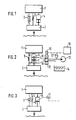
- FIG. 1 shows a passive suspension
- FIG. 2 shows an active suspension
- FIG. 3 shows a semi-active suspension
- FIG. 4 shows a diagram of damper work areas
- FIG. 5 shows a combination of active and semi-active suspension according to the invention.
- the passive suspension system shown in FIG. 1 has a steel spring 3 between a vehicle mass 1 and a wheel mass 2 for cushioning the vehicle body and, in parallel, a conventional, uncontrolled shock absorber 4.
- a schematically illustrated friction component is provided with the reference number 5.
- the suspension according to FIG. 2, which is also known per se, has a spring element 6 with a piston 7, which separates two working spaces 8 and 9 from one another, using the same reference numbers for corresponding parts, between vehicle mass 1 and wheel mass 2.
- Each working space 8 or 9 is connected via a line 10 or 11 to a 4/3-way solenoid valve 12 which monitors the connection of the working spaces 8 and 9 with a pump 13 or with a reservoir 14.
- a magnet 15 of the solenoid valve 12 is connected to an electronic control device 16, to which signals from level sensors or the like are also supplied in order to adapt the vehicle suspension to the respective vehicle or road conditions.
- the 4/3-way solenoid valve In its central position, the 4/3-way solenoid valve seals off the connection between the working spaces 8 and 9 with the pump 13 and the reservoir 14. In its second and third positions, it establishes such a connection, once a pump connection to the upper working chamber 8 and once a pump connection to the lower working chamber 9, each with an inverted reservoir connection.
- a damper 18 controllable via a magnet 17, a steel spring 3 and a friction component 5 are shown between the vehicle mass 1 and the wheel mass 2.
- Such a vehicle suspension is also known, it is referred to as semi-active.
- FIG. 4 shows in a diagram in which the damper force F is plotted on the ordinate and the piston speed V is plotted on the abscissa, the mode of operation of a passive series damper according to FIG. 1, the characteristics of which are designated by the reference numbers 19 and 20.
- the active suspension works according to FIG. 2 and in the two quadrants 21 and 23 the semi-active suspension works according to FIG. 3.
- the curves 25 and 26 show that the performance of the active suspension in quadrants 22 and 24 is limited by the pump capacity installed. If, for example, a power of 2 to 3 kW is to be provided per vehicle wheel, the necessary components such as the pump, high-pressure accumulator, lines and solenoid valve are correspondingly large, heavy and expensive.
- a semi-active suspension as shown in FIG. 3, is supplemented by an active suspension according to FIG. 2, but the latter is only designed so strongly that it only overcomes the frictional forces can.
- the work area 27 is represented in FIG. 4 by a single oblique hatching.
- the steel spring 3 (suspension spring) and a controllable damper 28 are arranged between the vehicle mass 1 and the wheel mass 2.
- the damper 28 is designed as a balanced damper with the same working spaces 29 and 30.
- a controllable throttle 31 can be actuated via a magnet 32.
- Two lines 33 and 34 connected to the damper 28, an upper and a lower one, are led to a 4/3-way solenoid valve 35 and this solenoid valve 35 is used to monitor the connection of a pressure generating device consisting of pump 36, accumulator 37 and reservoir 38 with the damper 28.
- the controllable cross-section of the 4/3-way solenoid valve 35 is relatively small and so small that the power controlled by the solenoid valve 35 is only sufficient to overcome the frictional forces in the entire suspension.
- the essence and the advantage of the present invention are that an installed pump power of only 50 to 100 W per vehicle wheel is sufficient to compensate for the percentage of the frictional force in the total force.
- the components required to install such low power are smaller, lighter, and significantly less expensive than active suspension. While the very high demands on the speed of the 4/3-way magnetic valve 12 pose a lot of problems with the active suspension according to FIG. 2, the dynamic demands on the small, low power consumption and only friction compensation 4 can be met / 3-way solenoid valve 35 very easily meet.
- the suspension according to FIG. 5 works like an active suspension with all of its advantages, particularly on a good road surface. At higher piston speeds, which lead to forces above the frictional force limit, the suspension according to FIG. 5 works like a semi-active suspension.
- damper valve throttle 31 and magnet 32
- 4/3-way solenoid valve 35 shown in FIG. 5 can also be replaced by a construction combined into a block.
Landscapes
- Engineering & Computer Science (AREA)
- Mechanical Engineering (AREA)
- Vehicle Body Suspensions (AREA)
- Fluid-Damping Devices (AREA)
Abstract
Description
- Die Erfindung bezieht sich auf eine Fahrzeugfederung nach der Gattung des Hauptanspruchs. Eine derartige Fahrzeugfederung ist bekannt (DE-OS 34 14 257).
- Mit einer solchen bekannten Federung wird der Durchgang von einer Stoßdämpferseite zur anderen durch eine Ventileinrichtung überwacht, die elektromagnetisch betätigbar ist. Eine solche semiaktive Federung ist deutlich besser als eine passive Federung.
- Eine aktive Federung, wie sie z.B. durch die DE-OS 27 38 455 bekannt ist, hat eine Hochdruck-Pumpe, einen Hochdruckspeicher und entsprechende Zumeßventile, und da diese Komponenten alle für sehr hohe Leistungen (bis 5 KW/Rad) ausgelegt werden müssen, ist eine solche Federung sehr teuer und für gewöhnliche Fahrzeuge unwirtschaftlich.
- Andererseits ist aber bekannt, daß auf einer sehr guten Straße die Reibung in einer Fahrzeug-Federung überwiegt. Eine aufwendige und teuere Steuerbarkeit eines Dämpfers bringt umso weniger Vorteile, je besser die Straße und je höher die Reibung in der Fahrzeugfederung sind.
- Diese Nachteile werden bei der eingangs genannten Fahrzeügfederung durch die kennzeichnenden Merkmale des Hauptanspruchs vermieden.
- Ein Ausführungsbeispiel der Erfindung ist in der Zeichnung dargestellt und in der nachfolgenden Beschreibung näher erläutert. Es zeigen Figur 1 eine passive Federung, Figur 2 eine aktive Federung, Figur 3 eine semiaktive Federung, Figur 4 ein Diagramm über Dämpfer-Arbeitsbereiche, und Figur 5 eine erfindungsgemäße Kombination aus aktiver und semiaktiver Federung.
- Das in der Figur 1 dargestellte passive Federungssystem hat zwischen einer Fahrzeugmasse 1 und einer Radmasse 2 zur Abfederung des Fahrzeugaufbaus eine Stahlfeder 3 und parallel dazu angeordnet einen gewöhnlichen, ungesteuerten Stoßdämpfer 4. Eine schematisch dargestellte Reibungskomponente ist mit der Bezugszahl 5 versehen.
- Die ebenfalls an sich bekannte Federung nach der Figur 2 hat - unter Verwendung der gleichen Bezugszahlen für entsprechende Teile - zwischen Fahrzeugmasse 1 und Radmasse 2 ein Federelement 6 mit einem Kolben 7, der zwei Arbeitsräume 8 und 9 voneinander trennt. Jeder Arbeitsraum 8 bzw. 9 ist über eine Leitung 10 bzw. 11 an ein 4/3-Wege-Magnetventil 12 angeschlossen, das die Verbindung der Arbeitsräume 8 und 9 mit einer Pumpe 13 bzw. mit einem Reservoir 14 überwacht.
- Ein Magnet 15 des Magnetventils 12 ist an eine elektronische Steuereinrichtung 16 angeschlossen, der auch Signale von Niveausensoren oder dgl. zugeführt werden, um die Fahrzeugfederung den jeweiligen Fahrzeug- bzw. Straßengegebenheiten anzupassen.
- Das 4/3-Wege-Magnetventil riegelt in seiner Mittelstellung die Verbindung der Arbeitsräume 8 und 9 mit der Pumpe 13 bzw. dem Reservoir 14 ab. In seiner zweiten und dritten Stellung stellt es eine solche Verbindung her, einmal eine Pumpenverbindung mit der oberen Arbeitskammer 8 und einmal eine Pumpenverbindung mit der unteren Arbeitskammer 9 jeweils mit umgekehrtem Reservoir-Anschluß.
- In der Figur 3 sind - wiederum unter Verwendung der gleichen Bezugszahlen für entsprechende Teile - zwischen der Fahrzeugmasse 1 und der Radmasse 2 ein über einen Magneten 17 steuerbarer Dämpfer 18, eine Stahlfeder 3 und eine Reibungskomponente 5 dargestellt. Eine solche Fahrzeugfederung ist ebenfalls bekannt, sie wird als semiaktiv bezeichnet.
- Die Figur 4 zeigt in einem Diagramm, bei dem auf der Ordinaten die Dämpferkraft F und auf der Abszisse die Kolbengeschwindigkeit V aufgetragen ist, die Arbeitsweise eines passiven Serien-Dämpfers entsprechend der Figur 1, dessen Kennlinien mit den Bezugszahlen 19 und 20 bezeichnet sind. In vier Quadranten 21, 22, 23 und 24 arbeitet die ak tive Federung nach der Figur 2 und in den zwei Quadranten 21 und 23 arbeitet die semiaktive Federung nach der Figur 3. An den Kurven 25 und 26 ist zu erkennen, daß die Leistungsfähigkeit der aktiven Federung in den Quadranten 22 und 24 durch die jewils installierte Pumpenleistung begrenzt ist. Wenn beispielsweise pro Fahrzeugrad eine Leistung von 2 bis 3 kW bereitgestellt werden soll, sind die erforderlichen Komponenten wie Pumpe, Hochdruckspeicher, Leitungen und Magnetventil entsprechend groß, schwer und teuer.
- Gemäß der in der Figur 5 dargestellten Erfindung wird eine semiaktive Federung, wie sie in der Figur 3 dargstellt ist, durch eine aktive Federung nach der Figur 2 ergänzt, wobei letztere aber gerade nur so stark ausgelegt ist, daß mit ihr lediglich die Reibungskräfte überwunden werden können. Der Arbeitsbereich 27 ist in der Figur 4 durch eine Einfach-Schrägschraffur dargestellt.
- In der Figur 5 sind zwischen der Fahrzeugmasse 1 und der Radmasse 2 die Stahlfeder 3 (Tragfeder) und ein steuerbarer Dämpfer 28 angeordnet. Der Dämpfer 28 ist als ausgeglichener Dämpfer mit gleichen Arbeitsräumen 29 und 30 ausgebildet. Eine steuerbare Drossel 31 ist über einen Magneten 32 betätigbar. Zwei an den Dämpfer 28 angeschlossene Leitungen 33 und 34, eine obere und untere, sind zu einem 4/3-Wege-Magnetvenil 35 geführt und dieses Magnetventil 35 dient zur Überwachung der Verbindung von einer aus Pumpe 36, Speicher 37 und Reservoir 38 bestehenden Druckbeschaffungseinrichtung mit dem Dämpfer 28. Der steuerbare Querschnitt des 4/3-Wege-Magnetventils 35 ist verhältnismäßig klein und zwar so klein, daß die vom Magnetventil 35 gesteuerte Leistung lediglich zur Überwindung der Reibungskräfte in der gesamten Federung ausreicht.
- Der Kern und der Vorteil der vorliegenden Erfindung bestehen nun also darin, daß zur Kompensation des nur einige Prozent betragenden Anteils der Reibkraft an der Gesamtkraft eine installierte Pumpen-Leistung von nur 50 bis 100 W pro Fahrzeugrad genügt. Die zur Installation einer solch geringen Leistung erforderlichen Komponenten sind im Vergleich zu einer aktiven Federung kleiner und leichter und erheblich preiswerter. Während die sehr hohen Anforderungen an die Schnelligkeit des 4/3-Wege-Magnetvetils 12 bei der aktiven Federung nach Figur 2 sehr viele Probleme aufwerfen, lassen sich die Dynamik-Forderungen an das kleine, nur einen geringen Strombedarf aufweisende und nur der Reibungskompensation dienende 4/3-Wege-Magnetventil 35 sehr leicht erfüllen.
- Bei sehr kleinen Kolbengeschwindigkeiten im Dämpfer 28 arbeitet die Federung nach der Figur 5 wie eine aktive Federung mit all ihren Vorteilen besonders auf guter Fahrbahn. Bei größeren Kolbengeschwindigkeiten, die zu Kräften über der Reibkraftgrenze führen, arbeitet die Federung nach der Figur 5 wie eine semiaktive Federung.
- Die in der Figur 5 dargstellte getrennte Bauweise von Dämpferventil (Drossel 31 und Magnet 32) und 4/3-Wege-Magnetvenitl 35 kann auch durch eine zu einem Block zusammengefügte Bauweise ersetzt werden.
Claims (3)
Applications Claiming Priority (2)
| Application Number | Priority Date | Filing Date | Title |
|---|---|---|---|
| DE3631876 | 1986-09-19 | ||
| DE19863631876 DE3631876A1 (de) | 1986-09-19 | 1986-09-19 | Fahrzeugfederung |
Publications (2)
| Publication Number | Publication Date |
|---|---|
| EP0261399A1 true EP0261399A1 (de) | 1988-03-30 |
| EP0261399B1 EP0261399B1 (de) | 1991-11-21 |
Family
ID=6309916
Family Applications (1)
| Application Number | Title | Priority Date | Filing Date |
|---|---|---|---|
| EP19870112088 Expired - Lifetime EP0261399B1 (de) | 1986-09-19 | 1987-08-20 | Fahrzeugfederung |
Country Status (4)
| Country | Link |
|---|---|
| US (1) | US4779895A (de) |
| EP (1) | EP0261399B1 (de) |
| JP (1) | JPS6382810A (de) |
| DE (2) | DE3631876A1 (de) |
Cited By (6)
| Publication number | Priority date | Publication date | Assignee | Title |
|---|---|---|---|---|
| EP0433606A1 (de) * | 1989-11-15 | 1991-06-26 | Robert Bosch Gmbh | Fahrzeugfederung |
| EP0424784A3 (en) * | 1989-10-26 | 1991-08-07 | Volkswagen Aktiengesellschaft | Hydraulic positioning equipment producing a positioning force which is controllable with regards to its direction and magnitude |
| EP0489121A4 (en) * | 1990-06-08 | 1993-12-29 | Monroe Auto Equipment Company | Method and apparatus for dynamic leveling |
| GB2310024A (en) * | 1996-02-06 | 1997-08-13 | Monroe Auto Equipment Co | Active suspension system |
| US6886837B2 (en) | 2000-03-30 | 2005-05-03 | Gibbs Technologies Limited | Hydraulic suspension strut for an amphibious vehicle |
| CN105904926A (zh) * | 2016-06-02 | 2016-08-31 | 厦门理工学院 | 一种客车用的半主动悬架及客车 |
Families Citing this family (41)
| Publication number | Priority date | Publication date | Assignee | Title |
|---|---|---|---|---|
| DE3737760A1 (de) * | 1987-11-06 | 1989-05-18 | Pfister Gmbh | Verfahren zum optimieren der fahreigenschaft von fahrzeugen |
| DE3823044C2 (de) * | 1988-07-07 | 1995-10-26 | Bosch Gmbh Robert | Federung für Fahrzeuge |
| DE3841771A1 (de) * | 1988-12-12 | 1989-11-09 | Daimler Benz Ag | Rad- bzw. achsabstuetzaggregat |
| DE3931857A1 (de) * | 1989-09-23 | 1991-04-04 | Bosch Gmbh Robert | Daempfungssystem |
| US5071157A (en) * | 1989-11-02 | 1991-12-10 | General Motors Corporation | Full vehicle suspension control |
| US5062658A (en) * | 1989-11-02 | 1991-11-05 | General Motors Corporation | Vehicle suspension control with real time gain switching |
| US5062657A (en) * | 1989-11-02 | 1991-11-05 | General Motors Corporation | On/off semi-active suspension control |
| DE4014466A1 (de) * | 1990-05-07 | 1991-11-14 | Bosch Gmbh Robert | Fahrzeugfederung |
| JP2626176B2 (ja) * | 1990-05-31 | 1997-07-02 | 日産自動車株式会社 | 能動型サスペンション |
| SE466796B (sv) * | 1990-08-10 | 1992-04-06 | Saab Scania Ab | Fjaedersystem med foerbaettrad resonansdaempning och ett foerfarande foer reglering av fjaedringssystemet |
| JP2805387B2 (ja) * | 1990-09-17 | 1998-09-30 | 三菱自動車工業株式会社 | 車両用アクティブサスペンション装置 |
| US5195772A (en) * | 1991-06-18 | 1993-03-23 | Ford Motor Company | Valve configuration for converting an active suspension system into a passive suspension system |
| US5232242A (en) * | 1991-06-18 | 1993-08-03 | Ford Motor Company | Power consumption limiting means for an active suspension system |
| JP2628945B2 (ja) * | 1991-06-25 | 1997-07-09 | 本田技研工業株式会社 | 能動型懸架装置 |
| SE505594C2 (sv) * | 1992-10-15 | 1997-09-22 | Oehlins Racing Ab | Anordning vid stötdämpararrangemang |
| GB9524091D0 (en) * | 1995-11-24 | 1996-01-24 | Statham John A | Vehicle parking device |
| US6076837A (en) * | 1998-02-03 | 2000-06-20 | Ford Motor Company | Method and apparatus for improving quality of actuator motion in a vehicle active tilt control system |
| DE10111551A1 (de) * | 2001-03-10 | 2002-09-12 | Bayerische Motoren Werke Ag | Aktives Fahrwerksystem eines Fahrzeugs |
| DE10352186B4 (de) * | 2003-07-11 | 2016-08-18 | Volkswagen Ag | Fahrzeug, insbesondere Kraftfahrzeug |
| FR2857300B1 (fr) * | 2003-07-11 | 2007-03-02 | Volkswagen Ag | Systeme de suspension et d'amortissement pour vehicule, et vehicule le comportant |
| US20050242532A1 (en) * | 2004-01-06 | 2005-11-03 | Deo Hrishikesh V | Suspension system with independent control of ride-height, stiffness and damping |
| EP1974965A1 (de) * | 2007-03-26 | 2008-10-01 | C.R.F. Società Consortile per Azioni | System zur Steuerung von Dämpfung, Roll- und Nickbewegungen eines Motorfahrzeuges mit einstellbarem Hydraulikantrieb |
| DE102009060999A1 (de) | 2009-06-24 | 2011-01-05 | German Gresser | Energieoptimiertes Elektrofahrzeug mit autarker Stromversorgung und Verfahren zur Stromerzeugung, bevorzugt aus kinetischer und Gravitationsenergie |
| CA2801334C (en) | 2010-06-03 | 2020-03-10 | Polaris Industries Inc. | Electronic throttle control |
| US9662954B2 (en) | 2012-11-07 | 2017-05-30 | Polaris Industries Inc. | Vehicle having suspension with continuous damping control |
| US9205717B2 (en) | 2012-11-07 | 2015-12-08 | Polaris Industries Inc. | Vehicle having suspension with continuous damping control |
| CN107406094B (zh) | 2014-10-31 | 2020-04-14 | 北极星工业有限公司 | 用于控制车辆的系统和方法 |
| EP3294582A1 (de) | 2015-05-15 | 2018-03-21 | Polaris Industries Inc. | Nutzfahrzeug |
| CN110121438B (zh) | 2016-11-18 | 2023-01-31 | 北极星工业有限公司 | 具有可调节悬架的车辆 |
| US10406884B2 (en) | 2017-06-09 | 2019-09-10 | Polaris Industries Inc. | Adjustable vehicle suspension system |
| CN111263702B (zh) | 2017-10-27 | 2023-08-25 | 日立安斯泰莫株式会社 | 控制悬架中的阻尼器摩擦影响 |
| US10946736B2 (en) | 2018-06-05 | 2021-03-16 | Polaris Industries Inc. | All-terrain vehicle |
| US10987987B2 (en) | 2018-11-21 | 2021-04-27 | Polaris Industries Inc. | Vehicle having adjustable compression and rebound damping |
| CN113767023B (zh) | 2019-04-30 | 2024-09-24 | 北极星工业有限公司 | 车辆 |
| US11691674B2 (en) | 2020-05-15 | 2023-07-04 | Polaris Industries Inc. | Off-road vehicle |
| US12187127B2 (en) | 2020-05-15 | 2025-01-07 | Polaris Industries Inc. | Off-road vehicle |
| CN120735865A (zh) | 2020-05-20 | 2025-10-03 | 北极星工业有限公司 | 用于非道路休闲车辆的可调悬架的系统和方法 |
| US11904648B2 (en) | 2020-07-17 | 2024-02-20 | Polaris Industries Inc. | Adjustable suspensions and vehicle operation for off-road recreational vehicles |
| MX2023006716A (es) | 2022-06-13 | 2023-12-14 | Polaris Inc | Tren de potencia para vehiculo utilitario. |
| USD1067123S1 (en) | 2023-01-20 | 2025-03-18 | Polaris Industries Inc. | Off-road vehicle |
| USD1120805S1 (en) | 2023-06-29 | 2026-03-31 | Polaris Industries Inc. | Body assembly for an off-road vehicle |
Citations (1)
| Publication number | Priority date | Publication date | Assignee | Title |
|---|---|---|---|---|
| FR2562843A1 (fr) * | 1984-04-14 | 1985-10-18 | Bosch Gmbh Robert | Dispositif de commande de la durete de la suspension d'un vehicule |
Family Cites Families (2)
| Publication number | Priority date | Publication date | Assignee | Title |
|---|---|---|---|---|
| DE2020292A1 (de) * | 1970-04-25 | 1971-11-18 | Bosch Gmbh Robert | Abstuetzsystem fuer Kraftfahrzeuge |
| DE2738455A1 (de) * | 1977-08-26 | 1979-03-01 | Daimler Benz Ag | Aktive schwingungsdaempfer |
-
1986
- 1986-09-19 DE DE19863631876 patent/DE3631876A1/de not_active Withdrawn
-
1987
- 1987-05-21 JP JP62122701A patent/JPS6382810A/ja active Pending
- 1987-08-03 US US07/081,070 patent/US4779895A/en not_active Expired - Fee Related
- 1987-08-20 DE DE8787112088T patent/DE3774650D1/de not_active Expired - Lifetime
- 1987-08-20 EP EP19870112088 patent/EP0261399B1/de not_active Expired - Lifetime
Patent Citations (1)
| Publication number | Priority date | Publication date | Assignee | Title |
|---|---|---|---|---|
| FR2562843A1 (fr) * | 1984-04-14 | 1985-10-18 | Bosch Gmbh Robert | Dispositif de commande de la durete de la suspension d'un vehicule |
Non-Patent Citations (2)
| Title |
|---|
| PATENT ABSTRACTS OF JAPAN, Band 10, Nr. 18 (M-448) [2075], 24. Januar 1986; & JP - A - 60 176 805 (KAYABA KOGYO) 10.09.1987 * |
| PATENT ABSTRACTS OF JAPAN, Band 9, Nr. 38 (M-358)[1761], 19. Februar 1985; & JP - A - 59 179 413 (SANWA SEIKI) 12.10.1984 * |
Cited By (7)
| Publication number | Priority date | Publication date | Assignee | Title |
|---|---|---|---|---|
| EP0424784A3 (en) * | 1989-10-26 | 1991-08-07 | Volkswagen Aktiengesellschaft | Hydraulic positioning equipment producing a positioning force which is controllable with regards to its direction and magnitude |
| EP0433606A1 (de) * | 1989-11-15 | 1991-06-26 | Robert Bosch Gmbh | Fahrzeugfederung |
| EP0489121A4 (en) * | 1990-06-08 | 1993-12-29 | Monroe Auto Equipment Company | Method and apparatus for dynamic leveling |
| GB2310024A (en) * | 1996-02-06 | 1997-08-13 | Monroe Auto Equipment Co | Active suspension system |
| GB2310024B (en) * | 1996-02-06 | 2000-05-17 | Monroe Auto Equipment Co | active suspension system |
| US6886837B2 (en) | 2000-03-30 | 2005-05-03 | Gibbs Technologies Limited | Hydraulic suspension strut for an amphibious vehicle |
| CN105904926A (zh) * | 2016-06-02 | 2016-08-31 | 厦门理工学院 | 一种客车用的半主动悬架及客车 |
Also Published As
| Publication number | Publication date |
|---|---|
| US4779895A (en) | 1988-10-25 |
| DE3631876A1 (de) | 1988-03-31 |
| JPS6382810A (ja) | 1988-04-13 |
| DE3774650D1 (de) | 1992-01-02 |
| EP0261399B1 (de) | 1991-11-21 |
Similar Documents
| Publication | Publication Date | Title |
|---|---|---|
| EP0261399B1 (de) | Fahrzeugfederung | |
| DE3414257C2 (de) | Federelement mit veränderbarer Härte für Fahrzeuge | |
| EP0300204B1 (de) | Dämpfungsvorrichtung | |
| DE2900325C2 (de) | ||
| EP0243613B1 (de) | Vorrichtung zur Dämpfung von Bewegungsabläufen | |
| EP0183039B1 (de) | Verfahren und Vorrichtung zum Steuern der Dämpferhärte eines Stossdämpfers für Fahrzeuge | |
| DE3306393C1 (de) | Selbstpumpendes hydropneumatisches Federbein mit innerer Niveauregelung | |
| DE2533866C3 (de) | Aufhängung für das Triebwerk am Fahrgestell eines Kraftfahrzeuges | |
| DE3524863A1 (de) | Verfahren und vorrichtung zum steuern der federhaerte, insbesondere bei fahrzeugen | |
| DE3881507T2 (de) | Vorrichtung für semi-aktive hydropneumatische Aufhängung und mit dieser Vorrichtung ausgestattetes Kraftfahrzeug. | |
| DE19844493A1 (de) | Hydropneumatisches Federungssystem | |
| EP1232883B1 (de) | Hydropneumatisches Fahrzeugaufhängungssystem | |
| DE69617567T2 (de) | Frei bewegliches Kolbenventil für hydraulischen Dämpferzylinder, insbesondere eines Einzelrohrdämpfers | |
| DE3500601A1 (de) | Federzylinder fuer fahrzeuge, insbesondere kraftfahrzeuge | |
| EP0551605B1 (de) | Regelbarer Schwingungsdämpfer für Kraftfahrzeuge | |
| DE10111551A1 (de) | Aktives Fahrwerksystem eines Fahrzeugs | |
| EP0444278B1 (de) | Vorrichtung zur aktiven Regelung von Aufbaubewegungen bei Kraftfahrzeugen | |
| DE2051272B2 (de) | Einrichtung zur aktiven Stabilisierung eines Fahrzeugaufbaus gegen Wankbewegungen bei Kurvenfahrt | |
| DE4027998C2 (de) | Aktives Aufhängungssystem für Kraftfahrzeuge | |
| DE4402182A1 (de) | Fahrzeuganhänger | |
| DE3936987C2 (de) | ||
| DE4193088C2 (de) | Hydraulischer Schwingungsdämpfer mit integrierter Nivellier-Regeleinrichtung | |
| DE4129610A1 (de) | Niveauregelsystem fuer kraftfahrzeuge | |
| EP0424784A2 (de) | Hydraulische Stelleinrichtung zur Erzeugung einer nach Richtung und Grösse steuerbaren Stellkraft | |
| DE4337816C2 (de) | Hydrauliksystem für ein Kraftfahrzeug |
Legal Events
| Date | Code | Title | Description |
|---|---|---|---|
| PUAI | Public reference made under article 153(3) epc to a published international application that has entered the european phase |
Free format text: ORIGINAL CODE: 0009012 |
|
| AK | Designated contracting states |
Kind code of ref document: A1 Designated state(s): DE FR GB IT SE |
|
| 17P | Request for examination filed |
Effective date: 19880817 |
|
| 17Q | First examination report despatched |
Effective date: 19901112 |
|
| GRAA | (expected) grant |
Free format text: ORIGINAL CODE: 0009210 |
|
| AK | Designated contracting states |
Kind code of ref document: B1 Designated state(s): DE FR GB IT SE |
|
| ET | Fr: translation filed | ||
| REF | Corresponds to: |
Ref document number: 3774650 Country of ref document: DE Date of ref document: 19920102 |
|
| GBT | Gb: translation of ep patent filed (gb section 77(6)(a)/1977) | ||
| ITF | It: translation for a ep patent filed | ||
| RAP4 | Party data changed (patent owner data changed or rights of a patent transferred) |
Owner name: ROBERT BOSCH GMBH |
|
| PLBE | No opposition filed within time limit |
Free format text: ORIGINAL CODE: 0009261 |
|
| STAA | Information on the status of an ep patent application or granted ep patent |
Free format text: STATUS: NO OPPOSITION FILED WITHIN TIME LIMIT |
|
| 26N | No opposition filed | ||
| EAL | Se: european patent in force in sweden |
Ref document number: 87112088.7 |
|
| PGFP | Annual fee paid to national office [announced via postgrant information from national office to epo] |
Ref country code: GB Payment date: 19950728 Year of fee payment: 9 |
|
| PGFP | Annual fee paid to national office [announced via postgrant information from national office to epo] |
Ref country code: FR Payment date: 19950816 Year of fee payment: 9 |
|
| PGFP | Annual fee paid to national office [announced via postgrant information from national office to epo] |
Ref country code: SE Payment date: 19950825 Year of fee payment: 9 |
|
| PG25 | Lapsed in a contracting state [announced via postgrant information from national office to epo] |
Ref country code: GB Effective date: 19960820 |
|
| PG25 | Lapsed in a contracting state [announced via postgrant information from national office to epo] |
Ref country code: SE Effective date: 19960821 |
|
| GBPC | Gb: european patent ceased through non-payment of renewal fee |
Effective date: 19960820 |
|
| PG25 | Lapsed in a contracting state [announced via postgrant information from national office to epo] |
Ref country code: FR Effective date: 19970430 |
|
| EUG | Se: european patent has lapsed |
Ref document number: 87112088.7 |
|
| REG | Reference to a national code |
Ref country code: FR Ref legal event code: ST |
|
| PGFP | Annual fee paid to national office [announced via postgrant information from national office to epo] |
Ref country code: DE Payment date: 19971024 Year of fee payment: 11 |
|
| PG25 | Lapsed in a contracting state [announced via postgrant information from national office to epo] |
Ref country code: DE Free format text: LAPSE BECAUSE OF NON-PAYMENT OF DUE FEES Effective date: 19990601 |
|
| PG25 | Lapsed in a contracting state [announced via postgrant information from national office to epo] |
Ref country code: IT Free format text: LAPSE BECAUSE OF NON-PAYMENT OF DUE FEES;WARNING: LAPSES OF ITALIAN PATENTS WITH EFFECTIVE DATE BEFORE 2007 MAY HAVE OCCURRED AT ANY TIME BEFORE 2007. THE CORRECT EFFECTIVE DATE MAY BE DIFFERENT FROM THE ONE RECORDED. Effective date: 20050820 |