EP0261427A2 - Amortisseur de choc bitubulaire - Google Patents
Amortisseur de choc bitubulaire Download PDFInfo
- Publication number
- EP0261427A2 EP0261427A2 EP87112373A EP87112373A EP0261427A2 EP 0261427 A2 EP0261427 A2 EP 0261427A2 EP 87112373 A EP87112373 A EP 87112373A EP 87112373 A EP87112373 A EP 87112373A EP 0261427 A2 EP0261427 A2 EP 0261427A2
- Authority
- EP
- European Patent Office
- Prior art keywords
- shock absorber
- liquid
- electrodes
- chamber
- throttle point
- Prior art date
- Legal status (The legal status is an assumption and is not a legal conclusion. Google has not performed a legal analysis and makes no representation as to the accuracy of the status listed.)
- Granted
Links
Images
Classifications
-
- F—MECHANICAL ENGINEERING; LIGHTING; HEATING; WEAPONS; BLASTING
- F16—ENGINEERING ELEMENTS AND UNITS; GENERAL MEASURES FOR PRODUCING AND MAINTAINING EFFECTIVE FUNCTIONING OF MACHINES OR INSTALLATIONS; THERMAL INSULATION IN GENERAL
- F16F—SPRINGS; SHOCK-ABSORBERS; MEANS FOR DAMPING VIBRATION
- F16F9/00—Springs, vibration-dampers, shock-absorbers, or similarly-constructed movement-dampers using a fluid or the equivalent as damping medium
- F16F9/32—Details
- F16F9/53—Means for adjusting damping characteristics by varying fluid viscosity, e.g. electromagnetically
- F16F9/532—Electrorheological [ER] fluid dampers
-
- F—MECHANICAL ENGINEERING; LIGHTING; HEATING; WEAPONS; BLASTING
- F16—ENGINEERING ELEMENTS AND UNITS; GENERAL MEASURES FOR PRODUCING AND MAINTAINING EFFECTIVE FUNCTIONING OF MACHINES OR INSTALLATIONS; THERMAL INSULATION IN GENERAL
- F16F—SPRINGS; SHOCK-ABSORBERS; MEANS FOR DAMPING VIBRATION
- F16F9/00—Springs, vibration-dampers, shock-absorbers, or similarly-constructed movement-dampers using a fluid or the equivalent as damping medium
- F16F9/10—Springs, vibration-dampers, shock-absorbers, or similarly-constructed movement-dampers using a fluid or the equivalent as damping medium using liquid only; using a fluid of which the nature is immaterial
- F16F9/14—Devices with one or more members, e.g. pistons, vanes, moving to and fro in chambers and using throttling effect
- F16F9/16—Devices with one or more members, e.g. pistons, vanes, moving to and fro in chambers and using throttling effect involving only straight-line movement of the effective parts
- F16F9/18—Devices with one or more members, e.g. pistons, vanes, moving to and fro in chambers and using throttling effect involving only straight-line movement of the effective parts with a closed cylinder and a piston separating two or more working spaces therein
-
- F—MECHANICAL ENGINEERING; LIGHTING; HEATING; WEAPONS; BLASTING
- F16—ENGINEERING ELEMENTS AND UNITS; GENERAL MEASURES FOR PRODUCING AND MAINTAINING EFFECTIVE FUNCTIONING OF MACHINES OR INSTALLATIONS; THERMAL INSULATION IN GENERAL
- F16F—SPRINGS; SHOCK-ABSORBERS; MEANS FOR DAMPING VIBRATION
- F16F9/00—Springs, vibration-dampers, shock-absorbers, or similarly-constructed movement-dampers using a fluid or the equivalent as damping medium
- F16F9/10—Springs, vibration-dampers, shock-absorbers, or similarly-constructed movement-dampers using a fluid or the equivalent as damping medium using liquid only; using a fluid of which the nature is immaterial
- F16F9/14—Devices with one or more members, e.g. pistons, vanes, moving to and fro in chambers and using throttling effect
- F16F9/16—Devices with one or more members, e.g. pistons, vanes, moving to and fro in chambers and using throttling effect involving only straight-line movement of the effective parts
- F16F9/18—Devices with one or more members, e.g. pistons, vanes, moving to and fro in chambers and using throttling effect involving only straight-line movement of the effective parts with a closed cylinder and a piston separating two or more working spaces therein
- F16F9/185—Bitubular units
- F16F9/187—Bitubular units with uni-directional flow of damping fluid through the valves
Definitions
- the invention relates to a two-tube shock absorber according to the preamble of the main claim.
- a shock absorber is known (US 34 66 055).
- the actual damper cylinder is located on the inside and is surrounded by an outer cylinder, so that an outer chamber is formed between the two cylinders.
- the damper piston moves in the inner cylinder. Decisive for his work is the area ratio of the total piston area to the ring area of the piston minus the piston rod cross-section.
- the known design has the disadvantage that the liquid is not pumped around in the outer chamber. With some liquids, a sediment therefore settles on the bottom of the cylinder, which on the one hand changes the structure of the liquid and on the other hand the full functionality of the shock absorber is no longer guaranteed.
- the aforementioned two-tube shock absorber with the characterizing features of the main claim has the advantage that the liquid is pumped around during the work of the shock absorber. Sediment cannot therefore settle.
- a rheological liquid is used as the liquid which separates relatively easily, i.e. dispersed particles settle.
- the invention now has the advantage that the entire volume of liquid is circulated during the work of the shock absorber as a result of rectified and complete flow.
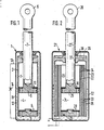
- FIG. 1 shows a two-pipe shock absorber with circulation of an ordinary liquid
- FIG. 2 shows a two-pipe shock absorber with electrorheological liquid.
- a two-tube shock absorber 1 has an inner chamber 3, 4 formed in a cylinder 2, in which a piston 5 is movable, which is carried by a piston rod 7 which projects outwards with its free end 6.
- the cylinder 2 has a bottom 8 in which an inward-opening check valve 9 is arranged.
- a check valve 10 is also arranged in the piston 5, and this opens from the chamber 4 to the chamber 3.
- the cylinder 2 is surrounded by an outer cylinder 11 which contains an outer chamber 12 which is only partially filled with liquid, the other part is formed by a gas cushion. As shown only schematically, there is a connecting line 13 between the inner chamber 3 and a lower point of the outer chamber 12. And a throttle point 14 is inserted into this connecting line 13.
- the piston 5 shrinks the inner chamber 4 when the distance (pressure stage) is reduced and, since the check valve 9 is closed, liquid is displaced from the chamber 4 into the chamber 3. Although this increases when the shock absorber is deflected, it cannot absorb the entire amount of liquid because the piston rod 7 is also immersed in the inner chamber 3. The excess liquid is pressed into the outer chamber 12 via the connecting line 13. The liquid must flow through the throttle 14, which, as the only throttle 14 in the system, is decisive for the throttling of the liquid circulation in the shock absorber in the working range of the compression stage.
- the check valve 10 closes and liquid from the chamber 3 is displaced into the outer chamber 12 via the connecting line 13 and the throttle 14. Since suction occurs in the inner chamber 4, the bottom check valve 9 opens and liquid is sucked from the outer chamber 12 into the inner chamber 4.
- an electrorheological liquid is used as the liquid. These are fluids, theirs Change the shear resistance depending on an electrical field acting on it.
- the two-tube shock absorber 21 has an inner chamber 23, 24 formed in a cylinder 22, in which a piston 25 is movable, which is supported by a piston rod 27 projecting outwards with its free end 26.
- the cylinder 22 has a bottom 28 in which an inward-opening check valve 29 is arranged.
- a check valve 30 is also arranged in the piston 25 and this opens from the chamber 24 to the chamber 23.
- the cylinder 22 is surrounded by an outer cylinder 31 which receives an outer chamber 32 which is only partially filled with liquid; the other part is formed by a gas cushion.
- the inner chamber 23 has a connection to a lower point of the outer chamber 32 via an axially directed, annular cylindrical passage 34.
- the passage 34 is formed by a plurality of concentrically nested cylinders 33 which are received by a hollow cylinder 35 and carried by the latter.
- the hollow cylinder 35, the inner cylinder 22 and a middle cylinder 33 form a ground electrode and two cylinders 33 arranged between them form insulated counter electrodes.
- the hollow cylinder 35 is covered at the top with an integrally formed cover 36 which has a through hole 37 for the piston rod 27 and has a recess 38 around the hole 37 for receiving a liquid supply which prevents air from penetrating into the inner cylinder.
- the check valve 30 closes and liquid from the chamber 23 is displaced via the passage 34 into the outer chamber 32. Since suction occurs in the inner chamber 24, the bottom check valve 29 opens and liquid is sucked from the outer chamber 32 into the inner chamber 24.
- the direction of flow through the throttle section is therefore the same for each direction of movement of the shock absorber.
- the volume flow is determined in the rebound direction by the ring surface of the piston and in the rebound direction by the cross section of the piston rod. Any or the same ratio of the damper forces for the tension and compression direction can also be set, since this only depends on the ratio of the ring area to the rod cross section.
- the ratio of shear gap length to electrode length can be set as desired, e.g. shorter or equal to the length of the inner cylinder, with which an adjustable viscous basic damping can be achieved.
- the adjustment range of the shock absorber can be increased by segmenting the electrode surface and by separately controlling the individual segments.
Landscapes
- Engineering & Computer Science (AREA)
- General Engineering & Computer Science (AREA)
- Mechanical Engineering (AREA)
- Physics & Mathematics (AREA)
- Electromagnetism (AREA)
- Fluid-Damping Devices (AREA)
Applications Claiming Priority (2)
| Application Number | Priority Date | Filing Date | Title |
|---|---|---|---|
| DE3632562 | 1986-09-25 | ||
| DE19863632562 DE3632562A1 (de) | 1986-09-25 | 1986-09-25 | Zweirohr-stossdaempfer |
Publications (3)
| Publication Number | Publication Date |
|---|---|
| EP0261427A2 true EP0261427A2 (fr) | 1988-03-30 |
| EP0261427A3 EP0261427A3 (en) | 1989-02-22 |
| EP0261427B1 EP0261427B1 (fr) | 1990-10-24 |
Family
ID=6310316
Family Applications (1)
| Application Number | Title | Priority Date | Filing Date |
|---|---|---|---|
| EP87112373A Expired - Lifetime EP0261427B1 (fr) | 1986-09-25 | 1987-08-26 | Amortisseur de choc bitubulaire |
Country Status (3)
| Country | Link |
|---|---|
| EP (1) | EP0261427B1 (fr) |
| JP (1) | JP2768460B2 (fr) |
| DE (2) | DE3632562A1 (fr) |
Cited By (24)
| Publication number | Priority date | Publication date | Assignee | Title |
|---|---|---|---|---|
| FR2613797A1 (fr) * | 1987-04-11 | 1988-10-14 | Bosch Gmbh Robert | Dispositif pour amortir des mouvements, en particulier sur des vehicules, utilisant un fluide d'amortissement sur lequel agit un champ electrostatique |
| EP0298266A3 (en) * | 1987-07-07 | 1989-07-26 | Bayerische Motoren Werke Ag | Fluid filled rubber mounting |
| EP0342882A3 (en) * | 1988-05-13 | 1990-05-02 | Toa Nenryo Kogyo Kabushiki Kaisha | Damping system for vibrating body |
| EP0382171A1 (fr) * | 1989-02-07 | 1990-08-16 | Tokai Rubber Industries, Ltd. | Amortisseur de chocs, utilisant un fluide électrorhéologique |
| EP0392274A1 (fr) * | 1989-04-14 | 1990-10-17 | Trw Inc. | Amortisseur rotatif à taux d'amortissement réglable |
| FR2652314A1 (fr) * | 1989-09-23 | 1991-03-29 | Bosch Gmbh Robert | Systeme d'amortissement comprenant un amortisseur rempli en partie au moins d'un fluide de pression et possedant une chambre de compensation. |
| FR2684422A1 (fr) * | 1991-12-03 | 1993-06-04 | Bosch Gmbh Robert | Amortisseur bi-tube ou la conduite de liaison est guidee par le piston d'amortissement. |
| EP0547866A1 (fr) * | 1991-12-18 | 1993-06-23 | Advanced Fluid Systems Limited | Vanne |
| US5259487A (en) * | 1992-07-14 | 1993-11-09 | The Lubrizol Corporation | Adjustable dampers using electrorheological fluids |
| EP0718523A1 (fr) * | 1994-12-09 | 1996-06-26 | BRIDGESTONE/FIRESTONE, Inc. | Amortisseur de vibrations à fluide électrorhéologique |
| WO1999058873A1 (fr) * | 1998-05-08 | 1999-11-18 | Carl Schenck Ag | Amortisseur de vibrations a base de liquides electrorheologiques et/ou magnetorheologiques |
| EP1101953A3 (fr) * | 1999-11-19 | 2004-01-02 | Schenck Pegasus GmbH | Moteur à actionnement fluidique pour les fluides électrorhéologiques |
| EP1908985A1 (fr) * | 2006-10-02 | 2008-04-09 | Delphi Technologies, Inc. | Amortisseur magnétorhéologique bi-tube |
| US7997392B2 (en) | 2007-05-21 | 2011-08-16 | Fludicon Gmbh | Vibration damper |
| DE102012016946A1 (de) * | 2012-08-28 | 2014-03-06 | Dt Swiss Ag | Federgabel, insbesondere für Fahrräder |
| WO2014135183A1 (fr) * | 2013-03-07 | 2014-09-12 | Fludicon Gmbh | Amortisseur de vibrations |
| CN104315064A (zh) * | 2014-09-10 | 2015-01-28 | 张家港市宏盛贸易有限公司 | 纺织机减震器 |
| US9273748B2 (en) | 2003-04-04 | 2016-03-01 | Millenworks | Magnetorheological damper system |
| CN105782327A (zh) * | 2016-04-27 | 2016-07-20 | 郑州大学 | 一种全阻尼通道有效的磁流变阻尼器 |
| US10054182B2 (en) | 2016-12-15 | 2018-08-21 | Tenneco Automotive Operating Company Inc. | Baffle tube for damper with electromechanical valve |
| US10704641B2 (en) | 2017-12-15 | 2020-07-07 | Tenneco Automotive Operating Company Inc. | Baffle for damper with electromechanical valve |
| US10837515B2 (en) | 2019-02-11 | 2020-11-17 | Tenneco Automotive Operating Company Inc. | Damper baffle tube with elastomeric skirt |
| US10987988B2 (en) | 2017-06-28 | 2021-04-27 | Tenneco Automotive Operating Company Inc. | Damper with volume reducing insert |
| US11007834B2 (en) | 2016-12-15 | 2021-05-18 | Tenneco Automotive Operating Company Inc. | Baffle tube for damper with electromechanical valve |
Families Citing this family (4)
| Publication number | Priority date | Publication date | Assignee | Title |
|---|---|---|---|---|
| DE19525271C2 (de) * | 1995-07-13 | 1998-05-14 | Joachim Blum | Antriebswelle |
| DE10320005B3 (de) * | 2003-05-06 | 2004-10-21 | Zf Sachs Ag | Schwingungsdämpfer mit feldkraftabhängig regelbarer Dämpfkraft |
| DE102012016948A1 (de) * | 2012-08-28 | 2014-03-06 | Inventus Engineering Gmbh | Dämpfer mit Einwegkreislauf und Verfahren |
| DE102016000849B8 (de) * | 2016-01-28 | 2017-07-13 | Hitachi Automotive Systems Europe Gesellschaft mit beschränkter Haftung | Schwingungsdämpfer |
Family Cites Families (6)
| Publication number | Priority date | Publication date | Assignee | Title |
|---|---|---|---|---|
| US2036955A (en) * | 1933-03-02 | 1936-04-07 | Gen Motors Corp | Shock absorbing device |
| FR1076192A (fr) * | 1953-02-13 | 1954-10-25 | Blaw Knox Cie Fse | Perfectionnements aux appareils à fluide tels que vérins, accumulateurs d'énergie, ou amortisseurs par exemple |
| GB756107A (en) * | 1953-07-29 | 1956-08-29 | Nat Res Dev | Improvements in and relating to shock absorbers or dampers |
| US3466055A (en) * | 1967-03-22 | 1969-09-09 | Monroe Belgium Nv | Vehicle leveling system |
| NL169216C (nl) * | 1977-12-12 | 1982-06-16 | Itt | Inrichting voor het verlagen van de druk op de zuigerstangpakking van een hydraulische telescopische schokdemper. |
| DE3443183A1 (de) * | 1984-11-27 | 1986-05-28 | Robert Bosch Gmbh, 7000 Stuttgart | Verfahren und vorrichtung zum steuern der daempferhaerte eines stossdaempfers fuer fahrzeuge |
-
1986
- 1986-09-25 DE DE19863632562 patent/DE3632562A1/de not_active Withdrawn
-
1987
- 1987-05-21 JP JP62122702A patent/JP2768460B2/ja not_active Expired - Lifetime
- 1987-08-26 DE DE8787112373T patent/DE3765732D1/de not_active Expired - Lifetime
- 1987-08-26 EP EP87112373A patent/EP0261427B1/fr not_active Expired - Lifetime
Cited By (34)
| Publication number | Priority date | Publication date | Assignee | Title |
|---|---|---|---|---|
| FR2613797A1 (fr) * | 1987-04-11 | 1988-10-14 | Bosch Gmbh Robert | Dispositif pour amortir des mouvements, en particulier sur des vehicules, utilisant un fluide d'amortissement sur lequel agit un champ electrostatique |
| EP0298266A3 (en) * | 1987-07-07 | 1989-07-26 | Bayerische Motoren Werke Ag | Fluid filled rubber mounting |
| EP0342882A3 (en) * | 1988-05-13 | 1990-05-02 | Toa Nenryo Kogyo Kabushiki Kaisha | Damping system for vibrating body |
| EP0382171A1 (fr) * | 1989-02-07 | 1990-08-16 | Tokai Rubber Industries, Ltd. | Amortisseur de chocs, utilisant un fluide électrorhéologique |
| US5000299A (en) * | 1989-02-07 | 1991-03-19 | Tokai Rubber Industries, Ltd. | Shock absorber using electro-viscous fluid |
| EP0392274A1 (fr) * | 1989-04-14 | 1990-10-17 | Trw Inc. | Amortisseur rotatif à taux d'amortissement réglable |
| US5263559A (en) * | 1989-09-23 | 1993-11-23 | Robert Bosch Gmbh | Damping system for a shock absorber having a one-way check valve |
| FR2652314A1 (fr) * | 1989-09-23 | 1991-03-29 | Bosch Gmbh Robert | Systeme d'amortissement comprenant un amortisseur rempli en partie au moins d'un fluide de pression et possedant une chambre de compensation. |
| US5293968A (en) * | 1991-12-03 | 1994-03-15 | Robert Bosch Gmbh | Dual-tube shock absorber |
| FR2684422A1 (fr) * | 1991-12-03 | 1993-06-04 | Bosch Gmbh Robert | Amortisseur bi-tube ou la conduite de liaison est guidee par le piston d'amortissement. |
| EP0547866A1 (fr) * | 1991-12-18 | 1993-06-23 | Advanced Fluid Systems Limited | Vanne |
| US5259487A (en) * | 1992-07-14 | 1993-11-09 | The Lubrizol Corporation | Adjustable dampers using electrorheological fluids |
| EP0581476A1 (fr) * | 1992-07-14 | 1994-02-02 | The Lubrizol Corporation | Amortisseur réglables utilisant fluides électrorhéologiques |
| AU658757B2 (en) * | 1992-07-14 | 1995-04-27 | Camp, Inc. | Adjustable dampers using electrorheological fluids |
| EP0718523A1 (fr) * | 1994-12-09 | 1996-06-26 | BRIDGESTONE/FIRESTONE, Inc. | Amortisseur de vibrations à fluide électrorhéologique |
| WO1999058873A1 (fr) * | 1998-05-08 | 1999-11-18 | Carl Schenck Ag | Amortisseur de vibrations a base de liquides electrorheologiques et/ou magnetorheologiques |
| EP1101953A3 (fr) * | 1999-11-19 | 2004-01-02 | Schenck Pegasus GmbH | Moteur à actionnement fluidique pour les fluides électrorhéologiques |
| US9273748B2 (en) | 2003-04-04 | 2016-03-01 | Millenworks | Magnetorheological damper system |
| EP1908985A1 (fr) * | 2006-10-02 | 2008-04-09 | Delphi Technologies, Inc. | Amortisseur magnétorhéologique bi-tube |
| US7997392B2 (en) | 2007-05-21 | 2011-08-16 | Fludicon Gmbh | Vibration damper |
| DE102012016946A1 (de) * | 2012-08-28 | 2014-03-06 | Dt Swiss Ag | Federgabel, insbesondere für Fahrräder |
| US8910963B2 (en) | 2012-08-28 | 2014-12-16 | Dt Swiss, Inc. | Suspension fork, in particular for a bicycle |
| EP2703686A3 (fr) * | 2012-08-28 | 2015-12-30 | DT Swiss AG | Fourche suspendue, en particulier pour vélos |
| US9662952B2 (en) | 2012-12-21 | 2017-05-30 | Hitachi Automotive Systems Europe Gmbh | Vibration damper |
| DE102013003841B4 (de) * | 2012-12-21 | 2016-11-24 | Fludicon Gmbh | Schwingungsdämpfer |
| WO2014135183A1 (fr) * | 2013-03-07 | 2014-09-12 | Fludicon Gmbh | Amortisseur de vibrations |
| CN104315064A (zh) * | 2014-09-10 | 2015-01-28 | 张家港市宏盛贸易有限公司 | 纺织机减震器 |
| CN105782327A (zh) * | 2016-04-27 | 2016-07-20 | 郑州大学 | 一种全阻尼通道有效的磁流变阻尼器 |
| CN105782327B (zh) * | 2016-04-27 | 2017-11-10 | 郑州大学 | 一种全阻尼通道有效的磁流变阻尼器 |
| US10054182B2 (en) | 2016-12-15 | 2018-08-21 | Tenneco Automotive Operating Company Inc. | Baffle tube for damper with electromechanical valve |
| US11007834B2 (en) | 2016-12-15 | 2021-05-18 | Tenneco Automotive Operating Company Inc. | Baffle tube for damper with electromechanical valve |
| US10987988B2 (en) | 2017-06-28 | 2021-04-27 | Tenneco Automotive Operating Company Inc. | Damper with volume reducing insert |
| US10704641B2 (en) | 2017-12-15 | 2020-07-07 | Tenneco Automotive Operating Company Inc. | Baffle for damper with electromechanical valve |
| US10837515B2 (en) | 2019-02-11 | 2020-11-17 | Tenneco Automotive Operating Company Inc. | Damper baffle tube with elastomeric skirt |
Also Published As
| Publication number | Publication date |
|---|---|
| EP0261427A3 (en) | 1989-02-22 |
| EP0261427B1 (fr) | 1990-10-24 |
| JPS6383421A (ja) | 1988-04-14 |
| DE3765732D1 (de) | 1990-11-29 |
| DE3632562A1 (de) | 1988-04-07 |
| JP2768460B2 (ja) | 1998-06-25 |
Similar Documents
| Publication | Publication Date | Title |
|---|---|---|
| EP0261427B1 (fr) | Amortisseur de choc bitubulaire | |
| EP1076782B1 (fr) | Amortisseur de vibrations a base de liquides electrorheologiques et/ou magnetorheologiques | |
| EP3746676B1 (fr) | Amortisseur de vibrations pour un véhicule | |
| DE4139821A1 (de) | Zweirohr-stossdaempfer | |
| DE2853914A1 (de) | Schwingungsdaempfer oder federbein mit einem hydraulisch-mechanischen zuganschlag | |
| DE102013001650B4 (de) | Zylinder-Kolben-Einheit mit Kolbendrossel | |
| WO2008141787A1 (fr) | Amortisseur d'oscillations | |
| DE2645501A1 (de) | Ventil | |
| DE4424991A1 (de) | Schwingungsdämpfer mit lastabhängig wirkender Dämpfung | |
| EP1635084B1 (fr) | Dispositif pour fixer les pièces mobiles | |
| DE102018130320A1 (de) | Schwingungsdämpfer im Fahrwerk eines Kraftfahrzeugs | |
| DE10155587C1 (de) | Lager mit magneto-rheologisch einstellbarer Dämpferkraft | |
| DE2308413A1 (de) | Stossdaempfer | |
| DE3529422A1 (de) | Dichtung fuer pneumatische, hydraulische oder hydropneumatische aggregate | |
| DE10343875B4 (de) | Schwingungsdämpfer mit hubabhängiger Dämpfkraft | |
| DE102018124353A1 (de) | Verstellvorrichtung für eine Axialkolbenmaschine | |
| DE19756443C1 (de) | Trennkolben für ein Schwingungsdämpfungssystem | |
| DE10207471B4 (de) | Hydraulischer Schwingungsdämpfer | |
| DE102016217114B4 (de) | Frequenzabhängige Dämpfventilanordnung | |
| DE3543156C2 (de) | Hydropneumatisches Federbein | |
| DE2221945A1 (de) | Hydraulischer Teleskopstossdaempfer,insbesondere fuer die Lenkung eines Kraftfahrzeugs | |
| EP0298245A2 (fr) | Dispositif d'amortissement | |
| WO2017182227A1 (fr) | Jambe de suspension hydropneumatique | |
| DE2721121A1 (de) | Gabelbein fuer motorraeder | |
| DE1655225A1 (de) | Arbeitskolben mit Ventilanordnung |
Legal Events
| Date | Code | Title | Description |
|---|---|---|---|
| PUAI | Public reference made under article 153(3) epc to a published international application that has entered the european phase |
Free format text: ORIGINAL CODE: 0009012 |
|
| AK | Designated contracting states |
Kind code of ref document: A2 Designated state(s): DE FR GB IT NL SE |
|
| PUAL | Search report despatched |
Free format text: ORIGINAL CODE: 0009013 |
|
| AK | Designated contracting states |
Kind code of ref document: A3 Designated state(s): DE FR GB IT NL SE |
|
| 17P | Request for examination filed |
Effective date: 19890718 |
|
| 17Q | First examination report despatched |
Effective date: 19891004 |
|
| GRAA | (expected) grant |
Free format text: ORIGINAL CODE: 0009210 |
|
| AK | Designated contracting states |
Kind code of ref document: B1 Designated state(s): DE FR GB IT NL SE |
|
| ET | Fr: translation filed | ||
| GBT | Gb: translation of ep patent filed (gb section 77(6)(a)/1977) | ||
| REF | Corresponds to: |
Ref document number: 3765732 Country of ref document: DE Date of ref document: 19901129 |
|
| ITF | It: translation for a ep patent filed | ||
| PLBE | No opposition filed within time limit |
Free format text: ORIGINAL CODE: 0009261 |
|
| STAA | Information on the status of an ep patent application or granted ep patent |
Free format text: STATUS: NO OPPOSITION FILED WITHIN TIME LIMIT |
|
| ITTA | It: last paid annual fee | ||
| 26N | No opposition filed | ||
| EAL | Se: european patent in force in sweden |
Ref document number: 87112373.3 |
|
| PGFP | Annual fee paid to national office [announced via postgrant information from national office to epo] |
Ref country code: SE Payment date: 19950825 Year of fee payment: 9 |
|
| PGFP | Annual fee paid to national office [announced via postgrant information from national office to epo] |
Ref country code: NL Payment date: 19950829 Year of fee payment: 9 |
|
| PG25 | Lapsed in a contracting state [announced via postgrant information from national office to epo] |
Ref country code: SE Effective date: 19960827 |
|
| PG25 | Lapsed in a contracting state [announced via postgrant information from national office to epo] |
Ref country code: NL Effective date: 19970301 |
|
| NLV4 | Nl: lapsed or anulled due to non-payment of the annual fee |
Effective date: 19970301 |
|
| EUG | Se: european patent has lapsed |
Ref document number: 87112373.3 |
|
| PGFP | Annual fee paid to national office [announced via postgrant information from national office to epo] |
Ref country code: GB Payment date: 19970814 Year of fee payment: 11 |
|
| PGFP | Annual fee paid to national office [announced via postgrant information from national office to epo] |
Ref country code: FR Payment date: 19970820 Year of fee payment: 11 |
|
| PG25 | Lapsed in a contracting state [announced via postgrant information from national office to epo] |
Ref country code: GB Free format text: LAPSE BECAUSE OF NON-PAYMENT OF DUE FEES Effective date: 19980826 |
|
| GBPC | Gb: european patent ceased through non-payment of renewal fee |
Effective date: 19980826 |
|
| PG25 | Lapsed in a contracting state [announced via postgrant information from national office to epo] |
Ref country code: FR Free format text: LAPSE BECAUSE OF NON-PAYMENT OF DUE FEES Effective date: 19990430 |
|
| REG | Reference to a national code |
Ref country code: FR Ref legal event code: ST |
|
| PGFP | Annual fee paid to national office [announced via postgrant information from national office to epo] |
Ref country code: DE Payment date: 20020925 Year of fee payment: 16 |
|
| PG25 | Lapsed in a contracting state [announced via postgrant information from national office to epo] |
Ref country code: DE Free format text: LAPSE BECAUSE OF NON-PAYMENT OF DUE FEES Effective date: 20040302 |
|
| PG25 | Lapsed in a contracting state [announced via postgrant information from national office to epo] |
Ref country code: IT Free format text: LAPSE BECAUSE OF NON-PAYMENT OF DUE FEES;WARNING: LAPSES OF ITALIAN PATENTS WITH EFFECTIVE DATE BEFORE 2007 MAY HAVE OCCURRED AT ANY TIME BEFORE 2007. THE CORRECT EFFECTIVE DATE MAY BE DIFFERENT FROM THE ONE RECORDED. Effective date: 20050826 |