EP0261431A1 - Schraubspindeleinrichtung mit Kugelumlaufmutter - Google Patents
Schraubspindeleinrichtung mit Kugelumlaufmutter Download PDFInfo
- Publication number
- EP0261431A1 EP0261431A1 EP87112420A EP87112420A EP0261431A1 EP 0261431 A1 EP0261431 A1 EP 0261431A1 EP 87112420 A EP87112420 A EP 87112420A EP 87112420 A EP87112420 A EP 87112420A EP 0261431 A1 EP0261431 A1 EP 0261431A1
- Authority
- EP
- European Patent Office
- Prior art keywords
- nut
- ball
- channel
- screw
- helical
- Prior art date
- Legal status (The legal status is an assumption and is not a legal conclusion. Google has not performed a legal analysis and makes no representation as to the accuracy of the status listed.)
- Ceased
Links
Images

Classifications
-
- F—MECHANICAL ENGINEERING; LIGHTING; HEATING; WEAPONS; BLASTING
- F16—ENGINEERING ELEMENTS AND UNITS; GENERAL MEASURES FOR PRODUCING AND MAINTAINING EFFECTIVE FUNCTIONING OF MACHINES OR INSTALLATIONS; THERMAL INSULATION IN GENERAL
- F16H—GEARING
- F16H25/00—Gearings comprising primarily only cams, cam-followers and screw-and-nut mechanisms
- F16H25/18—Gearings comprising primarily only cams, cam-followers and screw-and-nut mechanisms for conveying or interconverting oscillating or reciprocating motions
- F16H25/20—Screw mechanisms
- F16H25/22—Screw mechanisms with balls, rollers, or similar members between the co-operating parts; Elements essential to the use of such members
- F16H25/2204—Screw mechanisms with balls, rollers, or similar members between the co-operating parts; Elements essential to the use of such members with balls
- F16H25/2214—Screw mechanisms with balls, rollers, or similar members between the co-operating parts; Elements essential to the use of such members with balls with elements for guiding the circulating balls
Definitions
- This invention relates to ball bearing screw and nut assemblies, particularly for use in aircraft.
- the recirculating track may be cut into the external surface of the nut body or drilled therethrough.
- the thickness of the nut body is interfered with and may be considerably reduced by the track cut into, or through, the nut body.
- an external tube has been provided to facilitate recirculation of the ball bearings.
- a ball bearing screw and nut assembly comprising, a screw formed with a helical groove, a tubular nut body around said screw formed with an internal helical groove having a radius of curvature co-operating with said screw groove to define a helical channel, a plurality of anti-friction balls in said helical channel inter-connecting said nut body and screw whereby relative rotation therebetween provides relative axial motion, a cast stool channel-forming ball return guide mounted on the external surface of said nut body, said channel-forming ball return guide comprising a channel member extending transversely of the longitudinal axis of said assembly between first and second integral end portions, the internal radial dimension of said channel member being substantially equal to the diameter of each of said balls to define a recirculating passage of constant dimensions with the external surface of said nut body, and end passages through the wall of said nut body at each end of said channel member connecting the ends of said helical channel and said recirculating passage, said external surface being substantially smooth and un
- a ball-bearing screw 2 is formed with a helical groove 4 which projects through a tubular nut body 6 around the elongate screw 2.
- the nut body 6 is formed with a helical groove 8, as shown in Figure 2, which cooperates with the groove 4 to define a helical channel filled with anti-friction balls 10.
- the balls 10 interconnect the nut body 6 and the screw 2 in a conventional manner to permit relative axial movement therebetween when there is relative rotational motion between the nut body 6 and the screw 2.
- a channel-forming ball return guide member comprising a channel member 12 extending transversely of the longitudinal axis of the nut and screw assembly as shown in Figure 1.
- the channel member 12 is a steel investment casting and extends transversely of the longitudinal axis of the assembly between first and second integral end portions 14 and 16, the whole being cast as one unit.
- the portion 15 between the end portions 14 and 16 is of less thickness than the end portions.
- the channel member 12 has an internal radial dimension substantially equal to the diameter of each of the balls 10 so as to define a recirculating passage of constant dimensions with the external surface of the nut body.
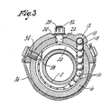
- the channel member 12 communicates with the helical channel, formed by helical grooves 4 and 8, by way of end passages, such as 18, through the wall of the nut body 6 at each end of the channel member 12(see Figure 3).
- Ball deflectors such as 20 ( Figure 3), are provided at each end of the helical channel so as to deflect the balls 10 as they move around the helical channel 4,8.
- Each ball deflector 20 is in the shape of a short helical portion, as illustrated, of generally circular cross-section adapted to extend into the thread formed on the screw 2.
- Each of the ball deflectors has a stem or stud 22 adapted to extend through a radial passage 24 as shown in Figure 3.
- the outer end of each stem 22 is threaded and operates to maintain the channel member 12 in position after a respective threaded castellated self-locking nut 26 or 28 is fastened down.
- the cotter pin 30 or 32 is used to ensure extra security of the self-locking nut 26 or 28 respectively.
- the ball deflector 20 is adapted to engage balls 10 moving anti-clockwise and to cause those balls to move outwardly through end passage 18.
- the balls 10 then traverse the recirculating passage formed by channel member 12 to the other end of the recirculating passage where they are deflected inwards through a corresponding end passage and again enter into engagement with the helical channel formed by the grooves 4 and 8.
- the balls 10 move in the opposite direction in the recirculating passage formed by channel member 12.
- channel member 12 is a steel investment casting.
- the process used is a precision casting process requiring minimum machining.
- items, such as the balls may break and interfere with,or jam the operation of the ball bearing screw and nut assembly. If broken balls jam, they could result in breaking the stud 22 off the ball deflector 20 whereby the ball deflector 20 would slide round. In some instances where this has happened, ball return tubes have been forced out of position and all the balls have been lost from the ball and screw assembly. Since there may be several such assemblies used in an aircraft, this can be a serious problem.
- Grease fittings are also provided, for example 40 and 42, in appropriate recesses as shown in Figure 1.
- wipers or scrapers 44 are provided in the illustrated assembly for aircraft.
Landscapes
- Engineering & Computer Science (AREA)
- General Engineering & Computer Science (AREA)
- Mechanical Engineering (AREA)
- Transmission Devices (AREA)
Applications Claiming Priority (2)
| Application Number | Priority Date | Filing Date | Title |
|---|---|---|---|
| CA516607 | 1986-08-27 | ||
| CA516607 | 1986-08-27 |
Publications (1)
| Publication Number | Publication Date |
|---|---|
| EP0261431A1 true EP0261431A1 (de) | 1988-03-30 |
Family
ID=4133781
Family Applications (1)
| Application Number | Title | Priority Date | Filing Date |
|---|---|---|---|
| EP87112420A Ceased EP0261431A1 (de) | 1986-08-27 | 1987-08-26 | Schraubspindeleinrichtung mit Kugelumlaufmutter |
Country Status (1)
| Country | Link |
|---|---|
| EP (1) | EP0261431A1 (de) |
Cited By (1)
| Publication number | Priority date | Publication date | Assignee | Title |
|---|---|---|---|---|
| US7578211B1 (en) * | 2004-03-29 | 2009-08-25 | Raytheon Company | Leadscrew drive with annular-shell leadscrew |
Citations (6)
| Publication number | Priority date | Publication date | Assignee | Title |
|---|---|---|---|---|
| US2925744A (en) * | 1959-01-29 | 1960-02-23 | Chrysler Corp | Ball bearing recirculating device |
| US3399581A (en) * | 1966-07-25 | 1968-09-03 | Sargent Industries | Ball nut and screw assembly |
| US3661030A (en) * | 1970-05-18 | 1972-05-09 | Precise Services Inc | Ball screw and nut combination |
| FR2204270A5 (de) * | 1972-10-20 | 1974-05-17 | Tech Integrale S | |
| GB1468607A (en) * | 1973-05-16 | 1977-03-30 | Tech Integrale Sa | Screw-and-nut mechanism with ball or roller recirculation |
| DE2715762A1 (de) * | 1976-04-10 | 1977-10-27 | Politechnika Warszawska | Waelzschraubgetriebe mit aeusserem umlauf von waelzelementen |
-
1987
- 1987-08-26 EP EP87112420A patent/EP0261431A1/de not_active Ceased
Patent Citations (6)
| Publication number | Priority date | Publication date | Assignee | Title |
|---|---|---|---|---|
| US2925744A (en) * | 1959-01-29 | 1960-02-23 | Chrysler Corp | Ball bearing recirculating device |
| US3399581A (en) * | 1966-07-25 | 1968-09-03 | Sargent Industries | Ball nut and screw assembly |
| US3661030A (en) * | 1970-05-18 | 1972-05-09 | Precise Services Inc | Ball screw and nut combination |
| FR2204270A5 (de) * | 1972-10-20 | 1974-05-17 | Tech Integrale S | |
| GB1468607A (en) * | 1973-05-16 | 1977-03-30 | Tech Integrale Sa | Screw-and-nut mechanism with ball or roller recirculation |
| DE2715762A1 (de) * | 1976-04-10 | 1977-10-27 | Politechnika Warszawska | Waelzschraubgetriebe mit aeusserem umlauf von waelzelementen |
Cited By (1)
| Publication number | Priority date | Publication date | Assignee | Title |
|---|---|---|---|---|
| US7578211B1 (en) * | 2004-03-29 | 2009-08-25 | Raytheon Company | Leadscrew drive with annular-shell leadscrew |
Similar Documents
| Publication | Publication Date | Title |
|---|---|---|
| US5193409A (en) | Multiple circuit internal ball nut return assembly with radial drop-in insert for ball screw devices | |
| US5622082A (en) | Ball nut and screw assemblies with improved crossovers | |
| US20030106385A1 (en) | Ball groove profile of ball screw | |
| DE19580454C1 (de) | Wälzlagereinheit mit einer Zentrierung und einem Flansch | |
| US2618166A (en) | Screw and nut transmission mechanism | |
| US2674899A (en) | Screw and nut assembly | |
| DE102019216610A1 (de) | Lager mit optischem Sensor und zugehöriger Nut | |
| DE4023636C2 (de) | Armatur zum Absperren einer Strömung | |
| EP3587864B1 (de) | Kugelmutterschmierung | |
| DE19612589A1 (de) | Lagerung | |
| DE102022106949A1 (de) | Lager für ein Wellgetriebe und Wellgetriebe mit einem solchen Lager | |
| US12428135B2 (en) | Actuator systems for flight control surface | |
| EP0261431A1 (de) | Schraubspindeleinrichtung mit Kugelumlaufmutter | |
| DE2207875B2 (de) | Kupplungsausrücklager | |
| US11794802B1 (en) | Steering column actuator assembly travel stop | |
| DE112019004538T5 (de) | Fahrzeugradlagervorrichtung | |
| US5535638A (en) | Antifriction screw drive | |
| DE102017109140B4 (de) | Kugelgewindetrieb | |
| US12209655B1 (en) | Actuator systems for flight control surface | |
| EP4004387B1 (de) | Befestigungselement und fertigungsverfahren | |
| DE3811970A1 (de) | Waelzlageranordnung | |
| US5943910A (en) | Telescopic ball nut and screw linear actuator and method of constucting and using it | |
| EP0239869A1 (de) | Bolzen zum Arretieren einer in einer Führungsbohrung längsverschieblichen Stange | |
| WO2019015710A1 (de) | Gewindemutter für einen kugelgewindetrieb | |
| DE112022001732T5 (de) | Radlagervorrichtung |
Legal Events
| Date | Code | Title | Description |
|---|---|---|---|
| PUAI | Public reference made under article 153(3) epc to a published international application that has entered the european phase |
Free format text: ORIGINAL CODE: 0009012 |
|
| AK | Designated contracting states |
Kind code of ref document: A1 Designated state(s): DE ES FR GB IT NL SE |
|
| 17P | Request for examination filed |
Effective date: 19880930 |
|
| 17Q | First examination report despatched |
Effective date: 19890323 |
|
| STAA | Information on the status of an ep patent application or granted ep patent |
Free format text: STATUS: THE APPLICATION HAS BEEN REFUSED |
|
| 18R | Application refused |
Effective date: 19900303 |
|
| RIN1 | Information on inventor provided before grant (corrected) |
Inventor name: FARNSWORTH, JOHN C.R. |