EP0261462A2 - Brûleur à tube radiant pourvu d'un lit de catalyseur pour four de traitement thermique - Google Patents
Brûleur à tube radiant pourvu d'un lit de catalyseur pour four de traitement thermique Download PDFInfo
- Publication number
- EP0261462A2 EP0261462A2 EP87112805A EP87112805A EP0261462A2 EP 0261462 A2 EP0261462 A2 EP 0261462A2 EP 87112805 A EP87112805 A EP 87112805A EP 87112805 A EP87112805 A EP 87112805A EP 0261462 A2 EP0261462 A2 EP 0261462A2
- Authority
- EP
- European Patent Office
- Prior art keywords
- tube
- burner
- jet
- radiant
- gas
- Prior art date
- Legal status (The legal status is an assumption and is not a legal conclusion. Google has not performed a legal analysis and makes no representation as to the accuracy of the status listed.)
- Granted
Links
Images


Classifications
-
- F—MECHANICAL ENGINEERING; LIGHTING; HEATING; WEAPONS; BLASTING
- F27—FURNACES; KILNS; OVENS; RETORTS
- F27D—DETAILS OR ACCESSORIES OF FURNACES, KILNS, OVENS OR RETORTS, IN SO FAR AS THEY ARE OF KINDS OCCURRING IN MORE THAN ONE KIND OF FURNACE
- F27D99/00—Subject matter not provided for in other groups of this subclass
- F27D99/0001—Heating elements or systems
- F27D99/0033—Heating elements or systems using burners
- F27D99/0035—Heating indirectly through a radiant surface
-
- C—CHEMISTRY; METALLURGY
- C21—METALLURGY OF IRON
- C21D—MODIFYING THE PHYSICAL STRUCTURE OF FERROUS METALS; GENERAL DEVICES FOR HEAT TREATMENT OF FERROUS OR NON-FERROUS METALS OR ALLOYS; MAKING METAL MALLEABLE, e.g. BY DECARBURISATION OR TEMPERING
- C21D1/00—General methods or devices for heat treatment, e.g. annealing, hardening, quenching or tempering
- C21D1/34—Methods of heating
- C21D1/52—Methods of heating with flames
-
- C—CHEMISTRY; METALLURGY
- C21—METALLURGY OF IRON
- C21D—MODIFYING THE PHYSICAL STRUCTURE OF FERROUS METALS; GENERAL DEVICES FOR HEAT TREATMENT OF FERROUS OR NON-FERROUS METALS OR ALLOYS; MAKING METAL MALLEABLE, e.g. BY DECARBURISATION OR TEMPERING
- C21D1/00—General methods or devices for heat treatment, e.g. annealing, hardening, quenching or tempering
- C21D1/74—Methods of treatment in inert gas, controlled atmosphere, vacuum or pulverulent material
- C21D1/76—Adjusting the composition of the atmosphere
- C21D1/763—Adjusting the composition of the atmosphere using a catalyst
Definitions
- the invention relates to a radiant tube burner for furnaces for the heat treatment of metallic workpieces under the action of a treatment gas, which is generated by catalytic conversion of a feed gas, with a jacket tube which has gas outlet openings at its end, a inner tube arranged coaxially at a distance from the jacket tube, in which at least a burner tube and an air supply tube are arranged, and with a catalyst bed which at least partially fills the space between the jacket tube and the inner tube.
- Radiant tube burners of this type are frequently used in heat treatment furnaces which are already equipped with simple radiant tube burners which are used exclusively for heating, one or some of these simple radiant tube burners being replaced by such special radiant tube burners.
- a known, such special jet tube burner in which a protective gas for the heat treatment of metallic workpieces, for example for the, by a catalytic conversion of a natural gas-air mixture Gas carburizing, bright hardening or carbonitriding is produced, has the construction described at the beginning and also has thermal insulation that acts against the furnace interior. This heat insulation is applied to the outside of the radiant tube burner and thereby increases its cross-sectional area. Its purpose is to prevent the protective gas generation from being adversely affected by different furnace temperatures (DE-OS 27 58 024).
- the heat treatment of metallic workpieces under the action of a treatment gas can only be carried out successfully if the composition of the treatment gas supplied to the furnace is optimally adapted to the respective type of heat treatment at any time.
- the treatment gas which may consist essentially of carbon monoxide, hydrogen and nitrogen, for example, by catalytic conversion of a feed gas, for example a natural gas / air mixture, in special jet tube burners of the type described in the introduction, the composition of the treatment gas is essentially determined by the composition of the feed gas and determined by the temperature prevailing in the catalyst bed. Both influencing factors therefore require precise regulation, which has not yet been satisfactorily achieved.
- the invention is therefore based on the object of improving the jet tube burner of the type described at the outset in such a way that precise regulation of the composition of the treatment gas is possible without significant structural outlay.
- At least one burner tube is displaceable in the longitudinal direction of the jet tube burner.
- the displaceability of at least one burner tube according to the invention creates a possibility of regulating the temperature distribution in the catalyst bed and thus the composition of the treatment gas with surprising accuracy.
- the temperature prevailing there and influenced by the fluctuating furnace temperature is measured via a temperature sensor arranged in the catalyst bed and fed to a control unit. If the temperature in the catalyst bed deviates from the target temperature, e.g.
- the burner tube which is stored in a fabric bushing, is pushed forwards or backwards by a motor until the desired temperature is reached.
- the jet tube burner according to the invention can achieve an accuracy of the composition of the treatment gas required in each case, which was not possible with the previously known methods.
- the radiant tube burner according to the invention has only one burner tube, it is advantageous if the burner tube is arranged along the longitudinal axis of the radiant tube burner, the air supply tube coaxially surrounds the burner tube and the space between the inner tube and the Air supply pipe is provided for the discharge of the burner exhaust gas.
- the idea underlying the invention of the displaceability of the burner tubes for the special case of a single burner tube is specified in a particularly simple manner.
- a particularly precise control of the composition of the treatment gas can be achieved with a radiant tube burner according to the invention with a plurality of burner tubes if the burner tubes are arranged on an imaginary cylinder surface coaxially to the longitudinal axis of the radiant tube burner, the air guide tube coaxially surrounds the imaginary cylinder surface at least partially and an exhaust pipe along the longitudinal axis of the Jet burner is arranged within the imaginary cylinder surface.
- the maximum of the thermal energy can always be supplied to the catalyst bed at the point where it is currently needed. This is of particular importance because the catalytic conversion of the feed gas in the catalyst bed is initially exothermic and only becomes endothermic in the further course, i.e. the supply of thermal energy can be concentrated primarily on the endothermic area.
- a further advantageous embodiment of the jet tube burner according to the invention is that the inner tube has bores which connect the interior of the inner tube through the wall of the inner tube with the intermediate space between the jacket tube and the inner tube.
- the composition of the treatment gas can, on the one hand, via the composition of the feed gas and, on the other hand, due to the high temperature of the burner exhaust gas, can be regulated via the temperature.
- the amount of burner exhaust gas to be fed to the feed gas is advantageously controlled via a valve arranged in the exhaust pipe of the jet pipe burner, by means of which the burner exhaust gas can be throttled.
- the holes in the wall of the inner tube either open directly into the catalyst bed or, in the case of jet tube burners with a shortened catalyst bed, into the space between the jacket tube and the inner tube that is not filled with catalyst. In special cases, both arrangements can also be provided.
- a particularly good heat transfer from the burner chamber into the catalyst bed is achieved if the burner tube or the burner tubes have swirl nozzles at their end, since this causes the burner flame and the burner exhaust gas to be swirled strongly by rotation.
- a further advantageous embodiment of the jet tube burner according to the invention is that the jacket tube is at least partially surrounded on the outside by an air-filled space which is circular in cross-section.
- the additional covering of the catalyst bed with an air-filled space acts as thermal insulation against the hot furnace atmosphere.
- this additional space can be designed as part of the air supply to the burner space and thus enables special combustion air preheating.
- the radiant tube burner according to the invention also has significant structural advantages, since it can be installed in a simple manner in all furnaces which are already operated with normal radiant tube burners for heating purposes.
- This advantage is achieved in that a jacket tube of an already existing, simple jet tube burner serving for heating purposes is used as the jacket tube for the jet pipe burner according to the invention. Due to this design of the radiant tube burner according to the invention, which touches on its construction, which is rationally thought through in all variants, it becomes possible to keep an already existing casing tube of one of the simple radiant tube burners of a furnace used for heating as a casing tube and all other parts in the manner of a smaller, complete special radiant tube burner to be installed in the casing pipe. It is therefore not necessary with the radiant tube burner according to the invention to enlarge the openings already present in the furnace wall.
- a jacket tube 4 is installed in the brick wall 1 of a heat treatment furnace via a support tube 2 on the one hand and a holder 3 on the other hand, and forms the outer casing of a jet tube burner according to the invention.
- the casing tube 4 can be a casing tube of a radiant tube burner for heating purposes, as is already available in large numbers in furnaces of this type. This has the advantage that the radiant tube burner according to the invention can be installed in the manner of a small, complete, special radiant tube burner without any particular design effort, in particular without enlarging the passage opening in the wall 1 of the furnace.
- a burner tube 7 is arranged along the longitudinal axis of the jet pipe burner, which has a nozzle 8 at its end.
- the space between the jacket tube 4 and the inner tube 5 is filled with a catalyst bed 9 up to a grid 10 and connected to a feed 11 for the feed gas, from which the treatment gas is generated by catalytic reaction in the catalyst bed 9.
- the space between the casing tube 4 and the inner tube 5 can be completely or partially filled with the catalyst bed 9.
- the catalyst bed 9 can consist of a specific catalyst or of mixtures or layers of different catalysts.
- the treatment gas leaves the catalyst bed 9 through gas outlet openings 12 which are attached to the end of the casing tube 4 and lead into the interior of the furnace.
- the interior of the air supply pipe 6 is with a Air supply 13 and the burner tube 10 connected to a burner gas supply 14.
- the space between the inner tube 5 and the air supply 6 serves as exhaust gas discharge and is therefore connected at its end to an exhaust pipe 15.
- a temperature sensor 16 in which a thermocouple for sensing the temperature in the catalyst bed 9 is slidably accommodated, and an analysis tube 17 with which the composition of the gas outlet openings 12 exits into the furnace chamber Treatment gas can be monitored.
- the burner tube 7 is in a fabric bushing 18 along the longitudinal axis of the jet tube burner, e.g. with the help of a motor, not shown, arranged displaceably, which is indicated in the figure by the dashed lines at 7a.
- a motor not shown
- the heat of the flame burning in the area of the nozzle 8 can be used in a targeted manner at that point of the catalyst bed 9 where it is optimally used with regard to the desired composition of the treatment gas.
- Bores 19 are provided in the wall of the inner tube 5, which connect the intermediate space between the inner tube 5 and the air supply tube 6 with the intermediate space between the inner tube 5 and the jacket tube 4, which is partially filled with the catalyst bed 9.
- Burner exhaust gas can be mixed into the treatment gas through the bores 19 and the composition thereof can thus be specifically changed.
- heat is supplied to both the catalyst bed 9 and the furnace itself, which can reduce the heating costs of the furnace.
- the bores 19 partly open directly into the catalyst bed 9, partly even into the empty space in front of it.
- an exhaust valve 20 with a pressure monitor 21 is provided in the exhaust line 15, which is in operative connection with the analysis tube 17, for example.
- the jet tube burner shown is operated with natural gas, which is also part of the feed gas for the production of the treatment gas.
- the ratio of natural gas to air for the burner is 1:10 to 1:20, while this ratio for the feed gas is precisely regulated between 1: 2.1 to 1: 2.6. If, as provided in accordance with the invention, this regulation takes place via an admixture of burner exhaust gas through the bores 19, a separate regulation of the composition of the feed gas introduced through the feed 11 can be omitted.
- FIG. 2 shows another embodiment of the jet tube burner according to the invention, which differs from that of FIG. 1 essentially in that instead of a single burner tube 7 (FIG. 1), several burner tubes 37 (FIG. 2) are provided, two of which are shown in the figure 2 are shown.
- the burner tubes 37 which are arranged on an imaginary cylinder surface coaxially to the longitudinal axis of the radiant tube burner, according to the invention can each be displaced parallel to the longitudinal axis of the radiant tube burner in the stuffing boxes 48, which is indicated by the dashed lines at 37a.
- the air is supplied via an air supply tube 36 which surrounds the burner tubes 37 to close to the end thereof, while the burner exhaust gas is removed via a separate exhaust pipe 52 along the longitudinal axis the radiant tube burner within the imaginary cylinder surface on which the burner tubes 37 lie, is arranged.
- the nozzles seated on the burner tubes 37 are designed as swirl nozzles 38, which cause a strong swirling of the burner flame and the burner exhaust gas.
- the influencing of the composition of the treatment gas by passing burner exhaust gas through the openings 19 in the inner tube 5 can be varied even further in this embodiment in that some of the openings 19 are provided at a location on the inner tube 5 which is wholly or partly still in terms of flow unused combustion air lies, ie
- hot air can also be added to the feed gas.
- This measure allows the partial pressure of carbon dioxide and water vapor in the catalyst bed 9 to be increased, which leads to a greater catalyst yield and increases the temperature in the endothermic reaction zone.
- the catalyst bed 9 can also be operated at a low furnace temperature.
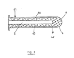
- FIG. 3 A further embodiment of the jet tube burner according to the invention is indicated in FIG. 3, all special components, which are shown and explained in detail in FIGS. 1 and 2, being omitted.
- the casing tube 4 is surrounded by a space 60 with an annular cross section through which air flows from the entry point 61 to the exit point 62.
- This air envelope in space 60 acts on the one hand as thermal insulation from the interior of the furnace and on the other hand, if it is part of the supply for the combustion air, as a preheating space for the latter.
- Another advantage of this embodiment of the jet tube burner according to the invention is that the temperature in the catalyst bed 9 drops because it is cooled by the cold combustion air. This makes the temperature more even over the length and the material stress less. Instead of air, fuel gas can also be passed through the preheating.
Landscapes
- Chemical & Material Sciences (AREA)
- Engineering & Computer Science (AREA)
- Mechanical Engineering (AREA)
- Thermal Sciences (AREA)
- Physics & Mathematics (AREA)
- Crystallography & Structural Chemistry (AREA)
- Materials Engineering (AREA)
- Metallurgy (AREA)
- Organic Chemistry (AREA)
- Chemical Kinetics & Catalysis (AREA)
- General Engineering & Computer Science (AREA)
- Gas Burners (AREA)
- Heat Treatment Of Articles (AREA)
Priority Applications (1)
| Application Number | Priority Date | Filing Date | Title |
|---|---|---|---|
| AT87112805T ATE60366T1 (de) | 1986-09-25 | 1987-09-02 | Strahlrohrbrenner mit katalysatorbett fuer waermebehandlungsoefen. |
Applications Claiming Priority (2)
| Application Number | Priority Date | Filing Date | Title |
|---|---|---|---|
| DE3632577 | 1986-09-25 | ||
| DE19863632577 DE3632577A1 (de) | 1986-09-25 | 1986-09-25 | Strahlrohrbrenner mit katalysatorbett fuer waermebehandlungsoefen |
Publications (3)
| Publication Number | Publication Date |
|---|---|
| EP0261462A2 true EP0261462A2 (fr) | 1988-03-30 |
| EP0261462A3 EP0261462A3 (en) | 1988-07-27 |
| EP0261462B1 EP0261462B1 (fr) | 1991-01-23 |
Family
ID=6310325
Family Applications (1)
| Application Number | Title | Priority Date | Filing Date |
|---|---|---|---|
| EP87112805A Expired - Lifetime EP0261462B1 (fr) | 1986-09-25 | 1987-09-02 | Brûleur à tube radiant pourvu d'un lit de catalyseur pour four de traitement thermique |
Country Status (4)
| Country | Link |
|---|---|
| EP (1) | EP0261462B1 (fr) |
| AT (1) | ATE60366T1 (fr) |
| DE (2) | DE3632577A1 (fr) |
| ES (1) | ES2020979B3 (fr) |
Cited By (4)
| Publication number | Priority date | Publication date | Assignee | Title |
|---|---|---|---|---|
| EP0435033A1 (fr) * | 1989-12-23 | 1991-07-03 | Linde Aktiengesellschaft | Procédé pour la préparation et la distribution de gaz de traitement pour traitements thermiques |
| EP0458183A3 (en) * | 1990-05-19 | 1992-04-01 | Linde Aktiengesellschaft | Method for making available treatment gases for heat treatments |
| EP0695807A1 (fr) * | 1994-08-03 | 1996-02-07 | Linde Aktiengesellschaft | Procédé pour le traitement thermique, notamment carburation, de pièces métalliques |
| FR2791419A1 (fr) * | 1999-03-25 | 2000-09-29 | Sunkiss Aeronautique | Equipement d'emission surfacique d'un rayonnement infra-rouge, du type tunnel, comportant des dispositifs de combustion catalytique |
Families Citing this family (2)
| Publication number | Priority date | Publication date | Assignee | Title |
|---|---|---|---|---|
| DE102008029001B3 (de) | 2008-06-20 | 2009-09-17 | Ipsen International Gmbh | Verfahren und Einrichtung zur Wärmebehandlung von metallischen Werkstoffen |
| DE102009038598B4 (de) | 2009-08-26 | 2017-06-22 | Ipsen International Gmbh | Verfahren und Vorrichtung zur Aufbereitung von Prozessgasen für Wärmebehandlungen von metallischen Werkstoffen/Werkstücken in Industrieöfen |
Family Cites Families (4)
| Publication number | Priority date | Publication date | Assignee | Title |
|---|---|---|---|---|
| FR1231064A (fr) * | 1959-02-23 | 1960-09-26 | Fours Ripoche | Tube radiant pour fours |
| FR2115558A5 (en) * | 1970-11-24 | 1972-07-07 | Bark Semen | Radiant furnace tube - of gas-fired, closed construction - has improved burner to reduce sooting |
| GB1306773A (en) * | 1971-04-14 | 1973-02-14 | Vnii Elektrotermicheskogo Obor | Apparatus for preparing a controlled exothermic atmosphere |
| DD131292A1 (de) * | 1977-03-28 | 1978-06-14 | Arnd Mueller | Einrichtung zur schutzgaserzeugung im ofenraum |
-
1986
- 1986-09-25 DE DE19863632577 patent/DE3632577A1/de not_active Withdrawn
-
1987
- 1987-09-02 DE DE8787112805T patent/DE3767626D1/de not_active Expired - Fee Related
- 1987-09-02 EP EP87112805A patent/EP0261462B1/fr not_active Expired - Lifetime
- 1987-09-02 ES ES87112805T patent/ES2020979B3/es not_active Expired - Lifetime
- 1987-09-02 AT AT87112805T patent/ATE60366T1/de not_active IP Right Cessation
Cited By (8)
| Publication number | Priority date | Publication date | Assignee | Title |
|---|---|---|---|---|
| EP0435033A1 (fr) * | 1989-12-23 | 1991-07-03 | Linde Aktiengesellschaft | Procédé pour la préparation et la distribution de gaz de traitement pour traitements thermiques |
| EP0458183A3 (en) * | 1990-05-19 | 1992-04-01 | Linde Aktiengesellschaft | Method for making available treatment gases for heat treatments |
| US5160380A (en) * | 1990-05-19 | 1992-11-03 | Linde Aktiengesellschaft | Process for improved preparation of treatment gas in heat treatments |
| EP0695807A1 (fr) * | 1994-08-03 | 1996-02-07 | Linde Aktiengesellschaft | Procédé pour le traitement thermique, notamment carburation, de pièces métalliques |
| FR2791419A1 (fr) * | 1999-03-25 | 2000-09-29 | Sunkiss Aeronautique | Equipement d'emission surfacique d'un rayonnement infra-rouge, du type tunnel, comportant des dispositifs de combustion catalytique |
| WO2000058678A1 (fr) * | 1999-03-25 | 2000-10-05 | Sunkiss | Equipement de chauffage par emission surfacique d'un rayonnement infrarouge, du type tunnel |
| JP2002540378A (ja) * | 1999-03-25 | 2002-11-26 | サンキス | 赤外線表面輻射によるトンネル型加熱装置 |
| US6494712B1 (en) | 1999-03-25 | 2002-12-17 | Sunkiss | Tunnel type heating equipment for surface transmission of infrared radiation |
Also Published As
| Publication number | Publication date |
|---|---|
| DE3767626D1 (de) | 1991-02-28 |
| DE3632577A1 (de) | 1988-05-05 |
| ATE60366T1 (de) | 1991-02-15 |
| EP0261462B1 (fr) | 1991-01-23 |
| EP0261462A3 (en) | 1988-07-27 |
| ES2020979B3 (es) | 1991-10-16 |
Similar Documents
| Publication | Publication Date | Title |
|---|---|---|
| DE10217913B4 (de) | Gasturbine mit Brennkammer zur flammenlosen Oxidation | |
| DE2417147C2 (de) | Brennkammeranordnung für Gasturbinen | |
| EP1532400B1 (fr) | Procede et dispositif pour faire bruler un melange combustible-oxydant | |
| DE2940431A1 (de) | Brennkammer mit abgestufter brennstoffeinspritzung und verfahren zum betreiben einer hochtemperaturbrennkammer | |
| DE2513499A1 (de) | Mit waermekonvektion arbeitender reformierofen und mit diesem ofen versehenes system | |
| CH680014A5 (fr) | ||
| CH627536A5 (de) | Verfahren zur durchfuehrung einer kontinuierlichen verbrennung eines kohlenstoffhaltigen brennstoffes. | |
| DE60011425T2 (de) | Sekundär reformierungsverfahren und brenner | |
| EP1209331A2 (fr) | Procédé d'alimentation en combustible et/ou d'énergie thermique dans un courant gazeux | |
| EP2986911A1 (fr) | Brûleur central pour système de brûleur multi-lances multi-combustibles | |
| DE2740537B2 (de) | Brenner für einen Regenerativ-Winderhitzer | |
| EP0261462B1 (fr) | Brûleur à tube radiant pourvu d'un lit de catalyseur pour four de traitement thermique | |
| DE2616085C2 (fr) | ||
| DE19647492A1 (de) | Verfahren und Vorrichtung zur Speisung einer Gasturbine sowohl mit flüssigen wie auch mit gasförmigen Brennstoffen | |
| EP0380192B1 (fr) | Procédé et dispositif pour le chauffage indirect d'un courant de gaz dans un espace de réaction pour une réaction endothermique | |
| DE68914051T2 (de) | Gasturbine. | |
| EP3246558B1 (fr) | Procede de fonctionnement d'un systeme de propulsion de fusee et systeme de propulsion de fusee | |
| DE102014211755A1 (de) | Vergaserkopf und Verfahren für die Partialoxidation von gasförmigen und flüssigen Vergasungsstoffen | |
| DE2712989C2 (de) | Zündofen zur Zündung von Sintermischungen | |
| DE2338147A1 (de) | Rotierender schachtofen mit gekuehltem brennerrohr | |
| DE102022103746A1 (de) | Brennersystem zur Erzeugung von Heißgas | |
| DE1962839C3 (de) | Vorrichtung zur Verbrennung von Abgas | |
| DE2525303C3 (de) | Gasbrenner | |
| DE2355282C3 (de) | Verfahren und Vorrichtung zur Änderung der Eindringtiefe des Windes in einen Hochofen | |
| DE1592955C3 (de) | Verfahren und Vorrichtung zur Herstellung von Ruß |
Legal Events
| Date | Code | Title | Description |
|---|---|---|---|
| PUAI | Public reference made under article 153(3) epc to a published international application that has entered the european phase |
Free format text: ORIGINAL CODE: 0009012 |
|
| AK | Designated contracting states |
Kind code of ref document: A2 Designated state(s): AT DE ES FR GB IT |
|
| PUAL | Search report despatched |
Free format text: ORIGINAL CODE: 0009013 |
|
| AK | Designated contracting states |
Kind code of ref document: A3 Designated state(s): AT DE ES FR GB IT |
|
| 17P | Request for examination filed |
Effective date: 19880927 |
|
| 17Q | First examination report despatched |
Effective date: 19900601 |
|
| ITF | It: translation for a ep patent filed | ||
| GRAA | (expected) grant |
Free format text: ORIGINAL CODE: 0009210 |
|
| AK | Designated contracting states |
Kind code of ref document: B1 Designated state(s): AT DE ES FR GB IT |
|
| REF | Corresponds to: |
Ref document number: 60366 Country of ref document: AT Date of ref document: 19910215 Kind code of ref document: T |
|
| REF | Corresponds to: |
Ref document number: 3767626 Country of ref document: DE Date of ref document: 19910228 |
|
| GBT | Gb: translation of ep patent filed (gb section 77(6)(a)/1977) | ||
| ET | Fr: translation filed | ||
| PLBE | No opposition filed within time limit |
Free format text: ORIGINAL CODE: 0009261 |
|
| STAA | Information on the status of an ep patent application or granted ep patent |
Free format text: STATUS: NO OPPOSITION FILED WITHIN TIME LIMIT |
|
| 26N | No opposition filed | ||
| PGFP | Annual fee paid to national office [announced via postgrant information from national office to epo] |
Ref country code: GB Payment date: 19940823 Year of fee payment: 8 |
|
| PGFP | Annual fee paid to national office [announced via postgrant information from national office to epo] |
Ref country code: FR Payment date: 19940909 Year of fee payment: 8 |
|
| PGFP | Annual fee paid to national office [announced via postgrant information from national office to epo] |
Ref country code: AT Payment date: 19940913 Year of fee payment: 8 |
|
| PGFP | Annual fee paid to national office [announced via postgrant information from national office to epo] |
Ref country code: ES Payment date: 19940930 Year of fee payment: 8 |
|
| PG25 | Lapsed in a contracting state [announced via postgrant information from national office to epo] |
Ref country code: GB Effective date: 19950902 Ref country code: AT Effective date: 19950902 |
|
| PG25 | Lapsed in a contracting state [announced via postgrant information from national office to epo] |
Ref country code: ES Free format text: LAPSE BECAUSE OF EXPIRATION OF PROTECTION Effective date: 19950904 |
|
| GBPC | Gb: european patent ceased through non-payment of renewal fee |
Effective date: 19950902 |
|
| PG25 | Lapsed in a contracting state [announced via postgrant information from national office to epo] |
Ref country code: FR Effective date: 19960531 |
|
| REG | Reference to a national code |
Ref country code: FR Ref legal event code: ST |
|
| PGFP | Annual fee paid to national office [announced via postgrant information from national office to epo] |
Ref country code: DE Payment date: 19980923 Year of fee payment: 12 |
|
| REG | Reference to a national code |
Ref country code: ES Ref legal event code: FD2A Effective date: 19990601 |
|
| PG25 | Lapsed in a contracting state [announced via postgrant information from national office to epo] |
Ref country code: DE Free format text: LAPSE BECAUSE OF NON-PAYMENT OF DUE FEES Effective date: 20000701 |
|
| PG25 | Lapsed in a contracting state [announced via postgrant information from national office to epo] |
Ref country code: IT Free format text: LAPSE BECAUSE OF NON-PAYMENT OF DUE FEES;WARNING: LAPSES OF ITALIAN PATENTS WITH EFFECTIVE DATE BEFORE 2007 MAY HAVE OCCURRED AT ANY TIME BEFORE 2007. THE CORRECT EFFECTIVE DATE MAY BE DIFFERENT FROM THE ONE RECORDED. Effective date: 20050902 |