EP0261468A2 - Aménagement pour centrifuge - Google Patents
Aménagement pour centrifuge Download PDFInfo
- Publication number
- EP0261468A2 EP0261468A2 EP87112853A EP87112853A EP0261468A2 EP 0261468 A2 EP0261468 A2 EP 0261468A2 EP 87112853 A EP87112853 A EP 87112853A EP 87112853 A EP87112853 A EP 87112853A EP 0261468 A2 EP0261468 A2 EP 0261468A2
- Authority
- EP
- European Patent Office
- Prior art keywords
- separation
- arrangement according
- channel
- separation container
- centrifuge
- Prior art date
- Legal status (The legal status is an assumption and is not a legal conclusion. Google has not performed a legal analysis and makes no representation as to the accuracy of the status listed.)
- Granted
Links
- 238000000926 separation method Methods 0.000 claims abstract description 152
- 239000000463 material Substances 0.000 claims abstract description 26
- 239000007788 liquid Substances 0.000 claims description 3
- 238000004519 manufacturing process Methods 0.000 abstract description 6
- 210000002381 plasma Anatomy 0.000 description 9
- 210000001772 blood platelet Anatomy 0.000 description 8
- 238000005119 centrifugation Methods 0.000 description 7
- 239000000306 component Substances 0.000 description 6
- 210000003743 erythrocyte Anatomy 0.000 description 5
- 238000003466 welding Methods 0.000 description 4
- 210000004369 blood Anatomy 0.000 description 3
- 239000008280 blood Substances 0.000 description 3
- 238000007789 sealing Methods 0.000 description 3
- FAPWRFPIFSIZLT-UHFFFAOYSA-M Sodium chloride Chemical compound [Na+].[Cl-] FAPWRFPIFSIZLT-UHFFFAOYSA-M 0.000 description 2
- PPBRXRYQALVLMV-UHFFFAOYSA-N Styrene Chemical compound C=CC1=CC=CC=C1 PPBRXRYQALVLMV-UHFFFAOYSA-N 0.000 description 2
- 230000000694 effects Effects 0.000 description 2
- 238000000605 extraction Methods 0.000 description 2
- 238000003780 insertion Methods 0.000 description 2
- 230000037431 insertion Effects 0.000 description 2
- 239000004800 polyvinyl chloride Substances 0.000 description 2
- 229920000915 polyvinyl chloride Polymers 0.000 description 2
- XLYOFNOQVPJJNP-UHFFFAOYSA-N water Substances O XLYOFNOQVPJJNP-UHFFFAOYSA-N 0.000 description 2
- 230000001133 acceleration Effects 0.000 description 1
- 238000004026 adhesive bonding Methods 0.000 description 1
- 230000002411 adverse Effects 0.000 description 1
- 230000004888 barrier function Effects 0.000 description 1
- 239000012503 blood component Substances 0.000 description 1
- 230000009172 bursting Effects 0.000 description 1
- 238000010276 construction Methods 0.000 description 1
- 230000001419 dependent effect Effects 0.000 description 1
- 239000013013 elastic material Substances 0.000 description 1
- 239000012530 fluid Substances 0.000 description 1
- 238000011010 flushing procedure Methods 0.000 description 1
- 210000000265 leukocyte Anatomy 0.000 description 1
- 238000000034 method Methods 0.000 description 1
- 230000003287 optical effect Effects 0.000 description 1
- 229920003023 plastic Polymers 0.000 description 1
- 239000004033 plastic Substances 0.000 description 1
- 229920000515 polycarbonate Polymers 0.000 description 1
- 239000004417 polycarbonate Substances 0.000 description 1
- 238000003825 pressing Methods 0.000 description 1
- 230000001681 protective effect Effects 0.000 description 1
- 230000009467 reduction Effects 0.000 description 1
Images


Classifications
-
- B—PERFORMING OPERATIONS; TRANSPORTING
- B04—CENTRIFUGAL APPARATUS OR MACHINES FOR CARRYING-OUT PHYSICAL OR CHEMICAL PROCESSES
- B04B—CENTRIFUGES
- B04B5/00—Other centrifuges
- B04B5/04—Radial chamber apparatus for separating predominantly liquid mixtures, e.g. butyrometers
- B04B5/0442—Radial chamber apparatus for separating predominantly liquid mixtures, e.g. butyrometers with means for adding or withdrawing liquid substances during the centrifugation, e.g. continuous centrifugation
-
- B—PERFORMING OPERATIONS; TRANSPORTING
- B04—CENTRIFUGAL APPARATUS OR MACHINES FOR CARRYING-OUT PHYSICAL OR CHEMICAL PROCESSES
- B04B—CENTRIFUGES
- B04B5/00—Other centrifuges
- B04B5/04—Radial chamber apparatus for separating predominantly liquid mixtures, e.g. butyrometers
- B04B5/0407—Radial chamber apparatus for separating predominantly liquid mixtures, e.g. butyrometers for liquids contained in receptacles
- B04B5/0428—Radial chamber apparatus for separating predominantly liquid mixtures, e.g. butyrometers for liquids contained in receptacles with flexible receptacles
Definitions
- the invention relates to a centrifuge arrangement according to the preamble of claim 1.
- a generic centrifuge arrangement is known for example from DE-OS 28 21 055. From this publication a centrifuge arrangement with a centrifuge rotor is known, the middle part of which has a channel closed on three sides. A separation container can be placed in this channel. Since this separation container consists of semi-rigid material, it lies against the walls of the channel during centrifugation due to the high pressures that occur, and is supported on its two side walls and its bottom wall.
- the final shape of the separation channel of the separation container is only created after insertion into the channel present in the central part of the centrifuge rotor.
- this channel can never be dimensioned and designed so precisely that the separation container lies evenly on all sides of the channel during centrifugation, which in turn has a negative effect on the separation performance of the known centrifuge arrangement.
- the dimension of the channel in the centrifuge body is limited, so that only certain dimensioned separation containers can be inserted.
- centrifuge arrangement is known from DE-OS 26 24 154, Fig. 4 there.
- This centrifuge arrangement has a centrifuge rotor which comprises a drive disk, a drive source connected to the drive disk and a separation container.
- the separation container itself has at least one circular separation channel closed on all sides and at least one separation chamber connected to it, which is connected to an outlet channel, while the separation channel is connected to at least one inlet channel. These channels lead from their connections to the separation chamber or the separation channel to the center of the separation container or the drive disk on which the separation container is fixed.
- the separation container consists of flexible, elastic material, such as polyvinyl chloride suitable for medical purposes, and is welded together, for example, from two circular pieces of the same shape. After attaching the inlet and outlet channels to the separation container, the latter is inserted into the drive disk of the centrifuge rotor and fastened to it by means of an additional cover. Furthermore, a hydraulic fluid must be introduced between the separation container and the surface of the centrifuge rotor for pressure equalization and to prevent the separation container from bursting.
- this known centrifuge arrangement has the disadvantage that a relatively high manufacturing outlay has to be carried out for it, since first two pieces of the same shape are made of flexible material, these are precisely connected to one another and then using a hydraulic protective liquid must be attached to the centrifuge rotor.
- the centrifuge arrangement according to the invention enables a completely uniform channel shape of the separation container, which has very small fluctuations in diameter and height. This in turn enables a particularly advantageous, laminar and even flow of the material to be centrifuged during operation, which is always good even when treating a wide variety of media Centrifugation results enabled.
- the separation container can be made to size accurately and in a simple manner and can be inserted extremely easily into the centrifuge rotor. This generally simplifies the handling of the centrifuge arrangement according to the invention, and material and cost reductions of the separation container, which can also be formed as a one-off part, also result from simple and easy construction.
- the separation chamber can, for example, be composed of only two parts, the separation chamber housing and the sealing cover.
- the separation container does not have to be individually balanced, but only in connection with the drive disc, i.e. only once per centrifuge arrangement. Balancing of the one-off part is not necessary, which leads to considerable simplifications in the case of asymmetrical duct arrangements. Furthermore, the separation container does not need its own connection to the drive source, which is very expensive to implement, but this connection is only present once on the drive pulley.
- rigid or semi-rigid material makes it possible to create clear-sighted areas which, for example, allow the creation of window areas for the arrangement of measuring devices, such as light barriers.
- the rigid and semi-rigid material also makes it possible to manufacture a very smooth, transparent surface and thus to obtain a stroboscopic view of the centrifugation process.
- a further advantageous separation can be achieved by accommodating two separating containers which are connected to one another for a two-stage separation on a drive disk.
- the separation container (1) is designed as a self-supporting part made of rigid or semi-rigid material, but the material has a certain flexibility. This has the advantage that the separation container (1) is dimensionally stable on the one hand, but due to its flexibility it can be deformed to a certain extent, in particular its diameter can be reduced, which makes it easier to handle, particularly when assembling it centrifuge arrangement according to the invention considerably simplified.
- the separation container (1) is designed as a circular ring, which, however, is not closed.
- the separation container (1) has two ends (2, 3) arranged opposite one another, which delimit an intermediate space (4). This makes it possible to move the two ends (2, 3) towards one another due to the flexibility of the material of the separation container (1), in that the ends are pressed together until they come to lie on one another.
- the end region (3) can be provided with a suitable handle part (5). Further details of the separation container (1) are explained below with reference to FIG. 4.
- the separation container (1) in Fig. 4 From the top view of the separation container (1) in Fig. 4, its circular ring shape is again indicated. It can also be seen that the separation container (1) in the example has a separation channel (6) which runs almost around the entire circumference of the separation container (1). The representation of the full circular separation channel has been omitted here for reasons of clarity. Furthermore, in the example case, an end region of the separation channel (6), which lies at the end (3) of the separation container (1), is provided with a pipe socket (7) which, in the final assembly state, is connected to an inlet channel for introducing material to be centrifuged by means of a piece of hose . The other end (4) is provided with a pipe socket (8) which, in the final assembly state, is connected to outlet channels from which the centrifuged components are derived.
- a separation chamber (9) is also arranged, which has an enlarged cross section compared to the separation channel (6) and whose height is preferably reduced compared to the height of the separation channel (6), for which purpose an inclined surface (9 ⁇ ) from the upper end region of the separation channel (6) can be provided up to a ceiling area of the separation chamber (9), which is not shown in FIG. 4. If this inclined surface (9 ⁇ ), which is shown in FIG. 1 as a dashed line, is provided, it serves to reduce the layer thickness, for example to attach an optical detector system. However, it is also possible to design the height of the separation chamber (9) in accordance with the height of the separation channel (6), that is to say not to reduce the height.
- the pipe socket (8) has three differently long discharge socket (10, 11, 11 ⁇ ), which extend into different areas of the separation chamber (9), so that it is possible to separate areas of different centrifuged components in the separation chamber (9) through the respective connection piece (10, 11, 11 ⁇ ) by means of hoses.
- the radially shortest nozzle (10) is used in the separation of blood to withdraw the lightest blood component, namely the plasma, while the radially longest nozzle (11 ⁇ ) is used to remove the heaviest component, i.e. the erythrocytes.
- the nozzle (11) which may be located radially approximately in the middle, on the other hand, is used to remove leukocytes or thrombocytes ("buffy coat"). In the case of pure plasma separation, this nozzle can be omitted.
- only one separation channel (6) is provided, however it is also possible to provide a plurality of separation channels which are connected to one another and which can be arranged, for example, concentrically one inside the other.
- the separation channel (6) has a rectangular cross-section, at least in larger partial areas, and comprises a channel floor (12) and fixed channel walls (13) or (vertical) fixed to the channel floor and substantially perpendicular to it. 14).
- the open side remaining accordingly is closed by means of a permanently attached liquid-sealing cover (15).
- the separation chamber (9) also has the walls (13, 14) and the channel floor (12), but the walls (13, 14) extend at a gradually increasing distance from each other, so that the from Fig. 4 in individual apparent form of the separation chamber (9) results.
- the separation chamber (9) is also provided with the cover (15), the shape of which is adapted to the course of the walls (13, 14) delimiting the separation chamber (9).
- a wall (16) is also provided which connects the walls (13, 14) and completely closes the separation chamber (9).
- a corresponding wall (17) is also provided in the end region (3), so that the separation channel (6) is closed on all sides and only via the connecting piece (7) and a recess provided in the wall (14) with the outer region in connection stands.
- the liquid-tight cover (15) is also to be said that it can be larger than the opening of the channel (6), the length of the cover (15) slightly larger than the length of the open channel (6) and its width at no point significantly greater than the distance between the outer surfaces of the channel walls (13, 14) from one another, but greater than the distance of the inner surfaces of the channel walls (13, 14) can be.
- the cover can also consist of several parts which close different sections of the channels.
- the area formed by the channel floor (12) can protrude beyond the side walls (13, 14) of the separation channel and thus form a base area on which several or different channel walls can be arranged in fixed positions relative to one another at certain positions.
- This base area for fixing the position of different channels or channel sections can also be formed between the channel walls, in particular on the open side of the channels, since here the greatest stability is required for the welding process.
- the wall thicknesses of the channel walls (13, 14) and the bottom wall (12) and the cover (15) are in the range from 0.5 to 5 mm and in particular in the range from 1.5 to 3 mm.
- the material used for the separation channel (6) and the separation chamber (9) can be plastic, in particular suitable for medical purposes, preferably as a clear material.
- plastic in particular suitable for medical purposes, preferably as a clear material.
- polycarbonate, PVC or styrene can be used.
- the walls (13, 14) and the bottom wall (12) can form a part to which the cover (15) can be applied, for example by gluing, ultrasonic welding, vibration welding or thermal welding. It is also possible to clamp the cover (15).
- the separation channel is sealed by the cover (15), it being possible for one To provide fixation aid for locking by providing guides.
- the drive disk (18) has a circular base plate (19), which can also be seen in FIG. 3.
- a cylindrical connecting piece (20) is arranged in the center of the base plate (19) and, according to FIG. 3, has a central passage recess (21) and an adjoining recess in the lower region, its diameter enlarged, for connecting a not shown Drive source is used, wherein the recess can be provided with a keyway profile, for example.
- the inlet and outlet hoses which are also not shown, are introduced into the passage recess (21), which lead to the separation chamber or to the separation channel and are closed by means of a lever (22) which is latched in.
- the drive disk (18) has a device (23) on which the separation container (1) is supported via the separation channel (6) or the separation chamber (9), this device (23) fixed to the drive pulley (18), or its base plate (19) is arranged. More precisely, the device (23) has surfaces facing the axis of rotation of the drive pulley (18), which in the example is a circular surface or wall (29) due to the circular design thereof. This wall (29) is substantially lower right on the drive pulley (18) or its base plate (19).
- a groove (24) is also formed in the surface of the base plate (19), which, as can be seen in detail from FIG. 3, adjoins the wall (29) and from there onto the axis of rotation of the drive disk (18 ) extends. 3, the width of the groove (24) is somewhat larger than the width of the separation channel (6), but this is not mandatory.
- the wall (29) extends around the radially outermost edge of the drive disk (18) and encompasses its entire circumference, thus forming a closed ring.
- the wall (29) has at its upper edge a radially inwardly extending projection (25) which also runs around the entire edge and preferably two, reduced in diameter, opposite Has areas (26), which can be seen in detail from Fig. 2.
- the projection (25) forms a ring around the entire circumference of the wall (29) with a smaller inner diameter than the inner diameter of the annular wall (29) and therefore overlaps at least a part of the separation container (1) or its cover (15 ), so that he can prevent the separation container (1) from slipping out in a direction away from the base plate (19).
- Fig. 3 illustrates the state in which the separation container (1) is inserted into the drive pulley (18).
- the separation container (1) has an elasticity due to the use of flexible material, which it does possible to move the ends (2, 3) towards each other, which in turn makes it possible to insert the separation container (1) into the drive disk (18) despite the projection (25).
- the ends (2, 3) are moved towards each other by pressing the handle pieces (5) together, the separation container (1) is inserted and then the ends (2, 3) are released, whereupon they move away from each other again due to the inherent elasticity of the separation container (1) and thus assume the position illustrated in FIG.
- this design leads to the advantage of reducing the material of the separation container (1), since the centrifugal forces which occur when the centrifuge arrangement is actuated can be transmitted to the wall (29) of the drive disc (18) and absorbed by it, so that the separation container (1) itself is relieved to a great extent and consequently it is not necessary to train it in a particularly stable manner.
- the channel shapes no consideration needs to be given to the balancing behavior, since the separation container (1) is only balanced together with the drive disk (18), so that counterweights only have to be attached to the drive disk. To do that To make it easier to insert or remove the separation container (1) and to lock it securely, there are further recesses (27) on the inner surface of the drive disk (18).
- the separation container (1) has corresponding projections (30) at its ends (2, 3). So that the behavior of the separation of the liquid can be observed, an opening (28) can be provided in the base plate (19) of the drive disk (18).
- the separation channel (6) In operation of the centrifuge arrangement according to the invention, in which, according to FIG. 3, the separation container (1) is inserted into the drive disk (18), blood is introduced into the separation channel (6), for example, via the inlet channel which is attached to the nozzle (7).
- erythrocytes for example, collect in the outer region, that is, adjacent to the wall (13), whereas blood plasma collects in the inner region, that is, adjacent to the wall (14).
- erythrocytes for example, collect in the outer region, that is, adjacent to the wall (13)
- blood plasma collects in the inner region, that is, adjacent to the wall (14).
- These two components migrate in connection with the platelets during centrifugation into the separation chamber (9), from which they can be removed separately via the connection piece (8) or the discharge connection piece (10, 11, 11 ⁇ ) according to FIG. 5.
- the separation channel (6) Due to the constant design of the cross section, the separation channel (6) in particular results in a laminar, uniform flow, which is important and
- the centrifuge arrangement according to the invention also has the advantage that it can be easily flushed out, since the channel shape is independent of the filling material and pressure and thus does not coincide after the material to be centrifuged has been removed.
- the expansion of the separation chamber to the outside favors the separation of the components of the material to be centrifuged, it being possible, for example, through an additionally recessed area (27) adjacent to the wall (16) of the separation chamber (9) Introduce saline solution to rinse completely without residue.
- This recessed area is connected to the end of the discharge nozzle (11 ⁇ ), so that in connection with a hose of a hose system, not shown, connected to the nozzle (7, 10, 11, 11 ⁇ ), erythrocytes or saline solution can be discharged.
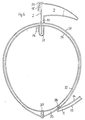
- the separation channel (1) is only formed almost as a semicircular element and contains at one end (2) the separation chamber (9) already described in its design according to FIGS. 4 and 5.
- the nozzle (10) leads the nozzle (10) as a U-shaped channel (31), which has a slope, to an egg-shaped second separation container (32).
- This separation container (32), which lies in the interior of the semicircular element, also has essentially a rectangular cross section and comprises a channel base (33) and fixed channel walls (34) and (35), which are fixedly connected to the channel base and perpendicular to it. The correspondingly remaining open side is closed by means of a permanently attached liquid-sealing lid.
- a connector (36) is provided on the separation container (32) on its inward-facing side and on the opposite side, the outermost point of the separation container (32), there is a further extraction connector (37). This is preferably formed obliquely inwards and downwards.
- the cross section of the separation container (32) can be enlarged in this area in order to obtain a collecting space.
- the supply nozzle (38) is arranged at the end of the separation channel (1) opposite the separation chamber (9).
- These two-stage separation containers (1,32) are arranged in a suitable manner on a drive disk (not shown in more detail).
- the blood is introduced into the separation container (1) via the feed connector (38), erythrocytes, for example, collecting in the outer region, ie adjacent to the wall (13), whereas in the inner region, that is to say adjacent to the wall (14), Bluplasma collects.
- erythrocytes for example, collecting in the outer region, ie adjacent to the wall (13), whereas in the inner region, that is to say adjacent to the wall (14), Bluplasma collects.
- These two components migrate in connection with the platelets into the separation chamber (9) during centrifugation, the erythrocytes being able to be removed via the extraction nozzle (11 ⁇ ).
- the platelet-containing plasma is passed via the discharge nozzle (10) or the U-shaped channel (31) into the egg-shaped second separation container (32).
- the platelets are separated from the blood plasma and, as a result of the centrifugal forces, they now reach the area of the discharge nozzle (37) from which the platelets are derived.
- the remaining plasma water reaches the opposite side of the separation container (32) to the nozzle (36), via which the plasma water is removed from the separation container (32).
- a combination arrangement of the separation container (1) according to FIG. 4 and the egg-shaped second separation container (32) would also be conceivable, whereby these are also by the nozzle (10) and channel (31) are connected, as just described. Only the feed connector (38) would be at the opposite end (3).
Landscapes
- Centrifugal Separators (AREA)
- External Artificial Organs (AREA)
Priority Applications (1)
| Application Number | Priority Date | Filing Date | Title |
|---|---|---|---|
| AT87112853T ATE82874T1 (de) | 1986-09-24 | 1987-09-03 | Zentrifugenanordnung. |
Applications Claiming Priority (2)
| Application Number | Priority Date | Filing Date | Title |
|---|---|---|---|
| DE3632500 | 1986-09-24 | ||
| DE19863632500 DE3632500A1 (de) | 1986-09-24 | 1986-09-24 | Zentrifugenanordnung |
Publications (3)
| Publication Number | Publication Date |
|---|---|
| EP0261468A2 true EP0261468A2 (fr) | 1988-03-30 |
| EP0261468A3 EP0261468A3 (en) | 1989-06-28 |
| EP0261468B1 EP0261468B1 (fr) | 1992-12-02 |
Family
ID=6310273
Family Applications (1)
| Application Number | Title | Priority Date | Filing Date |
|---|---|---|---|
| EP87112853A Expired - Lifetime EP0261468B1 (fr) | 1986-09-24 | 1987-09-03 | Aménagement pour centrifuge |
Country Status (6)
| Country | Link |
|---|---|
| US (1) | US4790807A (fr) |
| EP (1) | EP0261468B1 (fr) |
| JP (1) | JPS63158145A (fr) |
| AT (1) | ATE82874T1 (fr) |
| DE (2) | DE3632500A1 (fr) |
| ES (1) | ES2037043T3 (fr) |
Cited By (2)
| Publication number | Priority date | Publication date | Assignee | Title |
|---|---|---|---|---|
| EP0363120A3 (fr) * | 1988-10-07 | 1991-01-23 | Baxter International Inc. | Procédé et dispositif de traitement centrifuge de liquides |
| RU2161853C2 (ru) * | 1995-07-11 | 2001-01-10 | Кари Мартти Уллакко | Способ создания силы и движения путем управления ориентацией двойниковых зон материала и его применение |
Families Citing this family (18)
| Publication number | Priority date | Publication date | Assignee | Title |
|---|---|---|---|---|
| US5370802A (en) * | 1987-01-30 | 1994-12-06 | Baxter International Inc. | Enhanced yield platelet collection systems and methods |
| US5656163A (en) | 1987-01-30 | 1997-08-12 | Baxter International Inc. | Chamber for use in a rotating field to separate blood components |
| US5792372A (en) * | 1987-01-30 | 1998-08-11 | Baxter International, Inc. | Enhanced yield collection systems and methods for obtaining concentrated platelets from platelet-rich plasma |
| US4936820A (en) * | 1988-10-07 | 1990-06-26 | Baxter International Inc. | High volume centrifugal fluid processing system and method for cultured cell suspensions and the like |
| US5078671A (en) * | 1988-10-07 | 1992-01-07 | Baxter International Inc. | Centrifugal fluid processing system and method |
| AU652888B2 (en) * | 1991-12-23 | 1994-09-08 | Baxter International Inc. | Centrifugal processing system with direct access drawer |
| US5804079A (en) | 1991-12-23 | 1998-09-08 | Baxter International Inc. | Systems and methods for reducing the number of leukocytes in cellular products like platelets harvested for therapeutic purposes |
| US6007725A (en) | 1991-12-23 | 1999-12-28 | Baxter International Inc. | Systems and methods for on line collection of cellular blood components that assure donor comfort |
| EP0572656B1 (fr) * | 1991-12-23 | 1997-11-05 | Baxter International Inc. | Centrifugeuse a bol et bobine separables permettant d'acceder a la chambre de separation |
| US5549834A (en) | 1991-12-23 | 1996-08-27 | Baxter International Inc. | Systems and methods for reducing the number of leukocytes in cellular products like platelets harvested for therapeutic purposes |
| US5427695A (en) * | 1993-07-26 | 1995-06-27 | Baxter International Inc. | Systems and methods for on line collecting and resuspending cellular-rich blood products like platelet concentrate |
| US5525218A (en) * | 1993-10-29 | 1996-06-11 | Baxter International Inc. | Centrifuge with separable bowl and spool elements providing access to the separation chamber |
| DE19841835C2 (de) * | 1998-09-12 | 2003-05-28 | Fresenius Ag | Zentrifugenkammer für einen Zellseparator |
| WO2002062482A2 (fr) | 2000-11-02 | 2002-08-15 | Gambro, Inc. | Dispositifs de separation de fluides, systemes et / ou procedes reposant sur l'utilisation d'une configuration a entrainement par pression fluidique et / ou equilibree |
| US6890291B2 (en) | 2001-06-25 | 2005-05-10 | Mission Medical, Inc. | Integrated automatic blood collection and processing unit |
| US7037428B1 (en) | 2002-04-19 | 2006-05-02 | Mission Medical, Inc. | Integrated automatic blood processing unit |
| CN103454192B (zh) * | 2003-07-02 | 2016-08-24 | 泰尔茂比司特公司 | 一种用于提取端口中细胞分离室光学表面的光学单元 |
| JP2013538119A (ja) * | 2010-08-09 | 2013-10-10 | チャールズ,マーホ | 分離、センサ、及び計量分配制御システムを備える、血液遠心分離器 |
Family Cites Families (11)
| Publication number | Priority date | Publication date | Assignee | Title |
|---|---|---|---|---|
| DE2624154A1 (de) * | 1975-11-13 | 1977-05-26 | Ibm | Fluessigkeitsbehaelter |
| US4430072A (en) * | 1977-06-03 | 1984-02-07 | International Business Machines Corporation | Centrifuge assembly |
| US4094461A (en) * | 1977-06-27 | 1978-06-13 | International Business Machines Corporation | Centrifuge collecting chamber |
| US4387848A (en) * | 1977-10-03 | 1983-06-14 | International Business Machines Corporation | Centrifuge assembly |
| US4344560A (en) * | 1979-11-02 | 1982-08-17 | Asahi Kasei Kogyo Kabushiki Kaisha | Container, apparatus and method for separating platelets |
| DE2948177A1 (de) * | 1979-11-30 | 1981-06-04 | Dr. Eduard Fresenius Chemisch-Pharmazeutische Industrie Kg Apparatebau Kg, 6380 Bad Homburg | Separator fuer eine ultrazentrifuge |
| US4284498A (en) * | 1980-02-29 | 1981-08-18 | E. I. Du Pont De Nemours And Company | Apparatus for field flow fractionation |
| US4447221A (en) * | 1982-06-15 | 1984-05-08 | International Business Machines Corporation | Continuous flow centrifuge assembly |
| JPS5935267A (ja) * | 1982-08-20 | 1984-02-25 | Matsushita Electric Ind Co Ltd | マルチマイクロプロセツサ |
| JPS6146270A (ja) * | 1984-08-09 | 1986-03-06 | Jeol Ltd | 回転ジヨイント |
| US4708712A (en) * | 1986-03-28 | 1987-11-24 | Cobe Laboratories, Inc. | Continuous-loop centrifugal separator |
-
1986
- 1986-09-24 DE DE19863632500 patent/DE3632500A1/de not_active Withdrawn
-
1987
- 1987-09-03 ES ES198787112853T patent/ES2037043T3/es not_active Expired - Lifetime
- 1987-09-03 EP EP87112853A patent/EP0261468B1/fr not_active Expired - Lifetime
- 1987-09-03 AT AT87112853T patent/ATE82874T1/de not_active IP Right Cessation
- 1987-09-03 DE DE8787112853T patent/DE3782902D1/de not_active Expired - Lifetime
- 1987-09-23 US US07/100,236 patent/US4790807A/en not_active Expired - Lifetime
- 1987-09-24 JP JP62239906A patent/JPS63158145A/ja active Pending
Cited By (2)
| Publication number | Priority date | Publication date | Assignee | Title |
|---|---|---|---|---|
| EP0363120A3 (fr) * | 1988-10-07 | 1991-01-23 | Baxter International Inc. | Procédé et dispositif de traitement centrifuge de liquides |
| RU2161853C2 (ru) * | 1995-07-11 | 2001-01-10 | Кари Мартти Уллакко | Способ создания силы и движения путем управления ориентацией двойниковых зон материала и его применение |
Also Published As
| Publication number | Publication date |
|---|---|
| ATE82874T1 (de) | 1992-12-15 |
| EP0261468B1 (fr) | 1992-12-02 |
| US4790807A (en) | 1988-12-13 |
| DE3632500A1 (de) | 1988-04-07 |
| EP0261468A3 (en) | 1989-06-28 |
| ES2037043T3 (es) | 1993-06-16 |
| JPS63158145A (ja) | 1988-07-01 |
| DE3782902D1 (de) | 1993-01-14 |
Similar Documents
| Publication | Publication Date | Title |
|---|---|---|
| EP0261468B1 (fr) | Aménagement pour centrifuge | |
| DE69718148T2 (de) | Yerfahren zur zellseparation, speziell für thrombozyten, sowie hierfür geeigneter beutelsatz | |
| DE19615702C1 (de) | Labor-Zentrifuge | |
| EP0646380B1 (fr) | Séparateur d'air | |
| DE2262856C3 (de) | Flexibler Einsatzbehälter für eine Zentrifuge | |
| DE3879686T2 (de) | Rotor fuer eine zentrifuge. | |
| DE2901907C2 (fr) | ||
| DE3879777T2 (de) | Waerme- und stoffaustauscher. | |
| DE2821055A1 (de) | Zentrifugenanordnung | |
| EP0844015A2 (fr) | Dispositif de séparation ayant une membrane de fibre creuse | |
| WO2009021257A1 (fr) | Dispositif médical de séparation | |
| DE2835362B2 (de) | Vorrichtung zur Konditionierung einer Flüssigkeit in Analysezellen | |
| CH627953A5 (de) | Sammelkammer fuer zentrifuge. | |
| EP1144095A2 (fr) | Dispositif de concentration et/ou de purification de macromolecules en solution et procede de fabrication d'un tel dispositif | |
| DE3050758C2 (de) | Trennelement | |
| DE2640030C2 (fr) | ||
| EP0730086B1 (fr) | Séparateur cyclone pour la ventilation de carter d'un moteur à combustion interne avec une soupape de ventilation | |
| DE2553044C3 (de) | Zentrifuge zum Trennen von Probenflüssigkeiten | |
| DE2953260C2 (fr) | ||
| DE3202330C2 (de) | Im wesentlichen symmetrisch aufgebautes zweiteiliges Filtergehäuse aus Kunststoff | |
| DE60035268T2 (de) | Zentrifugenrotor mit Reaktionsantrieb | |
| DE3523223C2 (fr) | ||
| EP2542325A1 (fr) | Séparateur de brouillard d'huile avec au moins un filtre centrifuge | |
| DE4118501C2 (fr) | ||
| DE3634631C2 (de) | Zentrifuge zur Behandlung von Flüssigkeiten |
Legal Events
| Date | Code | Title | Description |
|---|---|---|---|
| PUAI | Public reference made under article 153(3) epc to a published international application that has entered the european phase |
Free format text: ORIGINAL CODE: 0009012 |
|
| AK | Designated contracting states |
Kind code of ref document: A2 Designated state(s): AT CH DE ES FR GB IT LI NL |
|
| PUAL | Search report despatched |
Free format text: ORIGINAL CODE: 0009013 |
|
| AK | Designated contracting states |
Kind code of ref document: A3 Designated state(s): AT CH DE ES FR GB IT LI NL |
|
| 17P | Request for examination filed |
Effective date: 19890714 |
|
| 17Q | First examination report despatched |
Effective date: 19900806 |
|
| GRAA | (expected) grant |
Free format text: ORIGINAL CODE: 0009210 |
|
| AK | Designated contracting states |
Kind code of ref document: B1 Designated state(s): AT CH DE ES FR GB IT LI NL |
|
| PG25 | Lapsed in a contracting state [announced via postgrant information from national office to epo] |
Ref country code: IT Free format text: LAPSE BECAUSE OF FAILURE TO SUBMIT A TRANSLATION OF THE DESCRIPTION OR TO PAY THE FEE WITHIN THE PRE;WARNING: LAPSES OF ITALIAN PATENTS WITH EFFECTIVE DATE BEFORE 2007 MAY HAVE OCCURRED AT ANY TIME BEFORE 2007. THE CORRECT EFFECTIVE DATE MAY BE DIFFERENT FROM THE ONE RECORDED.SCRIBED TIME-LIMIT Effective date: 19921202 |
|
| REF | Corresponds to: |
Ref document number: 82874 Country of ref document: AT Date of ref document: 19921215 Kind code of ref document: T |
|
| REF | Corresponds to: |
Ref document number: 3782902 Country of ref document: DE Date of ref document: 19930114 |
|
| ET | Fr: translation filed | ||
| GBT | Gb: translation of ep patent filed (gb section 77(6)(a)/1977) |
Effective date: 19930219 |
|
| REG | Reference to a national code |
Ref country code: ES Ref legal event code: FG2A Ref document number: 2037043 Country of ref document: ES Kind code of ref document: T3 |
|
| PLBE | No opposition filed within time limit |
Free format text: ORIGINAL CODE: 0009261 |
|
| STAA | Information on the status of an ep patent application or granted ep patent |
Free format text: STATUS: NO OPPOSITION FILED WITHIN TIME LIMIT |
|
| 26N | No opposition filed | ||
| PGFP | Annual fee paid to national office [announced via postgrant information from national office to epo] |
Ref country code: CH Payment date: 20010824 Year of fee payment: 15 |
|
| PGFP | Annual fee paid to national office [announced via postgrant information from national office to epo] |
Ref country code: ES Payment date: 20010829 Year of fee payment: 15 |
|
| REG | Reference to a national code |
Ref country code: GB Ref legal event code: IF02 |
|
| PG25 | Lapsed in a contracting state [announced via postgrant information from national office to epo] |
Ref country code: ES Free format text: LAPSE BECAUSE OF NON-PAYMENT OF DUE FEES Effective date: 20020904 |
|
| PGFP | Annual fee paid to national office [announced via postgrant information from national office to epo] |
Ref country code: AT Payment date: 20020919 Year of fee payment: 16 |
|
| PG25 | Lapsed in a contracting state [announced via postgrant information from national office to epo] |
Ref country code: CH Free format text: LAPSE BECAUSE OF NON-PAYMENT OF DUE FEES Effective date: 20020930 Ref country code: LI Free format text: LAPSE BECAUSE OF NON-PAYMENT OF DUE FEES Effective date: 20020930 |
|
| REG | Reference to a national code |
Ref country code: CH Ref legal event code: PL |
|
| PG25 | Lapsed in a contracting state [announced via postgrant information from national office to epo] |
Ref country code: AT Free format text: LAPSE BECAUSE OF NON-PAYMENT OF DUE FEES Effective date: 20030903 |
|
| REG | Reference to a national code |
Ref country code: ES Ref legal event code: FD2A Effective date: 20031011 |
|
| PGFP | Annual fee paid to national office [announced via postgrant information from national office to epo] |
Ref country code: NL Payment date: 20060918 Year of fee payment: 20 |
|
| PGFP | Annual fee paid to national office [announced via postgrant information from national office to epo] |
Ref country code: FR Payment date: 20060922 Year of fee payment: 20 Ref country code: GB Payment date: 20060922 Year of fee payment: 20 |
|
| PGFP | Annual fee paid to national office [announced via postgrant information from national office to epo] |
Ref country code: DE Payment date: 20061124 Year of fee payment: 20 |
|
| REG | Reference to a national code |
Ref country code: GB Ref legal event code: PE20 |
|
| NLV7 | Nl: ceased due to reaching the maximum lifetime of a patent |
Effective date: 20070903 |
|
| PG25 | Lapsed in a contracting state [announced via postgrant information from national office to epo] |
Ref country code: GB Free format text: LAPSE BECAUSE OF EXPIRATION OF PROTECTION Effective date: 20070902 |
|
| PG25 | Lapsed in a contracting state [announced via postgrant information from national office to epo] |
Ref country code: NL Free format text: LAPSE BECAUSE OF EXPIRATION OF PROTECTION Effective date: 20070903 |