EP0261532A1 - Eckverbinder für Hohlprofile - Google Patents
Eckverbinder für Hohlprofile Download PDFInfo
- Publication number
- EP0261532A1 EP0261532A1 EP87113373A EP87113373A EP0261532A1 EP 0261532 A1 EP0261532 A1 EP 0261532A1 EP 87113373 A EP87113373 A EP 87113373A EP 87113373 A EP87113373 A EP 87113373A EP 0261532 A1 EP0261532 A1 EP 0261532A1
- Authority
- EP
- European Patent Office
- Prior art keywords
- profile
- sections
- groove
- corner connector
- angle
- Prior art date
- Legal status (The legal status is an assumption and is not a legal conclusion. Google has not performed a legal analysis and makes no representation as to the accuracy of the status listed.)
- Granted
Links
- 125000006850 spacer group Chemical group 0.000 claims description 8
- 229910052751 metal Inorganic materials 0.000 claims description 7
- 239000002184 metal Substances 0.000 claims description 7
- 229910001234 light alloy Inorganic materials 0.000 abstract 1
- 210000002105 tongue Anatomy 0.000 description 24
- 230000000295 complement effect Effects 0.000 description 6
- 238000010276 construction Methods 0.000 description 5
- 238000004519 manufacturing process Methods 0.000 description 3
- 238000004026 adhesive bonding Methods 0.000 description 2
- 239000011521 glass Substances 0.000 description 2
- 230000001154 acute effect Effects 0.000 description 1
- 239000000853 adhesive Substances 0.000 description 1
- 230000001070 adhesive effect Effects 0.000 description 1
- 229910052782 aluminium Inorganic materials 0.000 description 1
- XAGFODPZIPBFFR-UHFFFAOYSA-N aluminium Chemical compound [Al] XAGFODPZIPBFFR-UHFFFAOYSA-N 0.000 description 1
- 238000002788 crimping Methods 0.000 description 1
- 238000005553 drilling Methods 0.000 description 1
- 239000000463 material Substances 0.000 description 1
- 229910001092 metal group alloy Inorganic materials 0.000 description 1
- 238000010120 permanent mold casting Methods 0.000 description 1
- 230000000717 retained effect Effects 0.000 description 1
- 238000000926 separation method Methods 0.000 description 1
- 230000035939 shock Effects 0.000 description 1
- 230000003068 static effect Effects 0.000 description 1
- 238000003860 storage Methods 0.000 description 1
- 230000007704 transition Effects 0.000 description 1
Images



Classifications
-
- E—FIXED CONSTRUCTIONS
- E06—DOORS, WINDOWS, SHUTTERS, OR ROLLER BLINDS IN GENERAL; LADDERS
- E06B—FIXED OR MOVABLE CLOSURES FOR OPENINGS IN BUILDINGS, VEHICLES, FENCES OR LIKE ENCLOSURES IN GENERAL, e.g. DOORS, WINDOWS, BLINDS, GATES
- E06B3/00—Window sashes, door leaves, or like elements for closing wall or like openings; Layout of fixed or moving closures, e.g. windows in wall or like openings; Features of rigidly-mounted outer frames relating to the mounting of wing frames
- E06B3/96—Corner joints or edge joints for windows, doors, or the like frames or wings
- E06B3/964—Corner joints or edge joints for windows, doors, or the like frames or wings using separate connection pieces, e.g. T-connection pieces
- E06B3/9644—L-shaped corner pieces having two articulated or flexible joined legs; Corner joints with variable angle
-
- E—FIXED CONSTRUCTIONS
- E06—DOORS, WINDOWS, SHUTTERS, OR ROLLER BLINDS IN GENERAL; LADDERS
- E06B—FIXED OR MOVABLE CLOSURES FOR OPENINGS IN BUILDINGS, VEHICLES, FENCES OR LIKE ENCLOSURES IN GENERAL, e.g. DOORS, WINDOWS, BLINDS, GATES
- E06B3/00—Window sashes, door leaves, or like elements for closing wall or like openings; Layout of fixed or moving closures, e.g. windows in wall or like openings; Features of rigidly-mounted outer frames relating to the mounting of wing frames
- E06B3/96—Corner joints or edge joints for windows, doors, or the like frames or wings
- E06B3/964—Corner joints or edge joints for windows, doors, or the like frames or wings using separate connection pieces, e.g. T-connection pieces
- E06B3/9645—Mitre joints
- E06B3/9646—Mitre joints using two similar connecting pieces each connected with one or the frame members and drawn together at the joint
-
- F—MECHANICAL ENGINEERING; LIGHTING; HEATING; WEAPONS; BLASTING
- F16—ENGINEERING ELEMENTS AND UNITS; GENERAL MEASURES FOR PRODUCING AND MAINTAINING EFFECTIVE FUNCTIONING OF MACHINES OR INSTALLATIONS; THERMAL INSULATION IN GENERAL
- F16B—DEVICES FOR FASTENING OR SECURING CONSTRUCTIONAL ELEMENTS OR MACHINE PARTS TOGETHER, e.g. NAILS, BOLTS, CIRCLIPS, CLAMPS, CLIPS OR WEDGES; JOINTS OR JOINTING
- F16B7/00—Connections of rods or tubes, e.g. of non-circular section, mutually, including resilient connections
- F16B7/04—Clamping or clipping connections
-
- F—MECHANICAL ENGINEERING; LIGHTING; HEATING; WEAPONS; BLASTING
- F16—ENGINEERING ELEMENTS AND UNITS; GENERAL MEASURES FOR PRODUCING AND MAINTAINING EFFECTIVE FUNCTIONING OF MACHINES OR INSTALLATIONS; THERMAL INSULATION IN GENERAL
- F16B—DEVICES FOR FASTENING OR SECURING CONSTRUCTIONAL ELEMENTS OR MACHINE PARTS TOGETHER, e.g. NAILS, BOLTS, CIRCLIPS, CLAMPS, CLIPS OR WEDGES; JOINTS OR JOINTING
- F16B7/00—Connections of rods or tubes, e.g. of non-circular section, mutually, including resilient connections
- F16B7/04—Clamping or clipping connections
- F16B7/044—Clamping or clipping connections for rods or tubes being in angled relationship
- F16B7/0446—Clamping or clipping connections for rods or tubes being in angled relationship for tubes using the innerside thereof
Definitions
- the invention relates to a corner connector with two legs which are at an angle other than 180 degrees and can be inserted into hollow profiles with a cavity circumscribed by a rectangle.
- corner angles For the production of corner connections on miter-cut hollow profiles, a large number of "corner angles" made in permanent mold casting are available, provided that they are smaller profile cross-sections and 90-degree corner connections, as are predominantly used in window and door construction. However, such corner angles do not allow corner connections to be made at an angle other than 90 degrees or even butt joints, i.e. the straight line up of such hollow profiles.
- the invention is therefore based on the object 'of specifying a corner connector of the type described at the outset, with which corner connections of almost any degree of angle can be produced which can withstand a high load in the vertical and horizontal directions.
- Such a corner connector can easily be produced from extruded profiles of corresponding cross-section by plane separating cuts which run perpendicular to a plane of symmetry in which the cross-sectional axis of the profile also lies, but which at the same time run at a corresponding angle to the longitudinal axis of the profile.
- the profile sections have such an equal length that the distances between the end faces produced by the separating cuts (always seen in the normal direction to the end faces) correspond to the clear height of the hollow profile, so that the relevant profile sections, hereinafter referred to as "sections", are just in the cavity of the associated hollow profile can be inserted.
- the abutting cavities of the two hollow profiles are always completely filled in cross-section, i.e. Particularly in the area of the miter joint, good profile guidance and thus an absolutely closed gap is achieved. This makes the connection more stable against lateral forces (due to wind pressure).
- the subject of the invention enables the connection of hollow profiles with almost any height dimensions, without the need for special connecting elements.
- These additional tongue-and-groove connections cannot "open” either, since they lie within the hollow profile that has been pushed on with small tolerances and to which they are additionally glued and / or screwed.
- box profiles is understood in addition to box-shaped profiles which are closed on all sides and also those which are open on one side (C-profiles) and box profiles which have additional profile projections on one or more sides, for example those into which windows and other facade elements are inserted can.
- C-profiles box profiles which have additional profile projections on one or more sides, for example those into which windows and other facade elements are inserted can.
- Such profiles are described, for example, in the book “Building with aluminum", 1983, pages 110 and 111.
- the spring starting from its cylindrical surface, is preferably connected to the rest of the profile via a web with a trapezoidal cross section.
- the groove arranged on the opposite side then has a complementary shape.
- the profile has a minimum wall thickness of 10 mm along the cross-sectional axis A-A and mirror-symmetrical to this.
- a web of appropriate wall thickness is formed, which is used to drill holes and threads for fastening screws at any intervals.
- the screw axes generally do not run parallel to the longitudinal profile axis.
- no prefabricated screw channels can be provided for this type of attachment.
- the specified minimum wall thickness creates the required freedom of design. In particular, this allows the screws or the screw heads to be moved to a location that is not visible when the profile frame is viewed from the side.
- a particularly advantageous embodiment of the subject matter of the invention is characterized in that the tongue and groove> are connected to one another by a web having the minimum wall thickness, from which flanges in the area of the tongue and groove originate, the surface parts of which face the tongue or open into the groove represent abutment surfaces described above for the creation of a further profile section.
- the flanges represent the lever arms for the support described above, and the abutting surfaces are preferably perpendicular to the cross-sectional axis A-A.
- the surface parts of the flanges which point outward from the cross-sectional axis AA each have a spacing B which corresponds to the clear dimension of the width of the cavity in the profile.
- the flanges fill the whole at least in places Internal cross section of the cavities of the hollow profiles to be connected, in particular in the immediate vicinity of the miter joint, so that excellent guidance of the hollow profiles in the miter joint is ensured.
- spacer ribs are arranged between the flanges in the middle of the web, and if the surface parts of the flanges and the spacer ribs pointing outwards from the cross-sectional axis AA on each side of the web are in a common plane Ei or E2 ends that run parallel to the cross-sectional axis AA.
- the legs of the corner connector can be glued over a large area to the long side walls of the hollow profiles.
- the adhesive bond is promoted further 'when the outwardly facing, in the planes E, and E2 surfaces of the flanges and the spacer ribs are provided with a micro-profiling.
- This micro-profiling is a triangular rib, which is separated from one another by such grooves, the depth of the corrugation being between 0.2 and 0.4 mm and the flank angle being 90 degrees.
- the corner connector described above makes it possible to produce corner connections in which hollow profiles can be aligned with one another at a wide variety of angles between 90 degrees and almost 180 degrees. This is made possible by the fact that the two flat end faces of each profile section produced by a separating cut run at an angle ⁇ of almost 90 degrees to 45 degrees to the longitudinal axis of the profile.
- the subject matter of the invention is preferably suitable for producing corner connections in which the hollow profiles enclose angles between 100 degrees and 160 degrees. This is made possible by the fact that the end faces of the profile sections extend at an angle ⁇ of 80 to 50 degrees to the longitudinal axis of the profile.
- a light metal extruded profile 1 which has a long cross-sectional axis A-A and is mirror-symmetrical to this.
- the longitudinal axis of the profile runs perpendicular to the plane of the drawing, so that a cross-sectional axis A-A and the longitudinal axis of the profile define a plane of symmetry which also runs perpendicular to the plane of the drawing.
- the groove 2 and the tongue 3 are delimited on most of their circumference by cylindrical surfaces 4 and 5. Starting from its cylindrical surface 5, the spring 3 is connected to the remaining part of the profile via a web 6 with a trapezoidal cross section.
- the tongue and groove are complementary to one another, and the trapezoidal web 6 corresponds to an opening 7 of the groove 2 which is also trapezoidal in cross section. It goes without saying that all transitions are well rounded.
- tongue and groove are only connected by a web 10, which for the reasons given above has a minimum wall thickness of 10 mm.
- a pair of flanges 11 are arranged in the area of the tongue 3, while a pair of flanges 12 are provided in the area of the groove 2.
- the surface parts of the flanges 11 facing the tongue 3 form the abutting surfaces 8, while the surface parts of the abutting surfaces 9 opening into the groove 2 are formed by the flanges 12. It can be seen that the abutting surfaces 8 and 9 each run perpendicular to the cross-sectional axis A-A.
- a pair of spacer ribs 13 is provided in a mirror-symmetrical arrangement.
- the surface parts of the flanges 11 and 12 and the spacing ribs 13 which point outward from the cross-sectional axis AA lie on each side of the web 10 in a common plane E or E2, which run parallel to the cross-sectional axis AA, so that the abutting surfaces 8 and 9 and the levels E and E2 outline a rectangle, the intangible parts of which are shown in dash-dot lines.
- This rectangle has the width "B", which corresponds to the inside width of the hollow profiles to be connected.
- the outward-facing surface parts of the flanges 11 and 12 and the spacing ribs 13 lying in the planes Ei and E2 are provided with a micro-profiling "M", by means of which the bonding with the respectively pushed-on hollow profiles is improved.
- screw channels 14 are arranged in the spacer ribs 13 in a symmetrical arrangement on both sides of the cross-sectional axis AA, which, however, can only be used if the end faces of the individual profile sections run perpendicular to the profile longitudinal axis, that is to say if the end faces coexist the profile cross-section are identical.
- a butt connector for the straight-line connection of two hollow profiles can be produced from two profiles according to FIG. 1, the narrow walls of the hollow profile running perpendicular to the axes of the screw channels 14.
- a template can be used to drill the hollow profile exactly above the screw channels 14, so that a reliable screw connection between the profile sections and the hollow profiles can be produced in the manner indicated.
- the joint of the hollow profiles is then exactly in the plane of the abutting surfaces 8 and 9.
- each groove base 15 is formed by the web 10.
- an undercut 16 into which a further fastening element (not shown here) can be inserted, which has a complementary, T-shaped cross section.
- Figure 2 shows a junction of two profile sections S, and S 2 , which form a tongue and groove connection 16.
- the axis of the spring 3 runs just as perpendicular to the plane of the drawing as the flanges 11 and 12 or the abutting surfaces 8 and 9 between them (FIG. 1).
- the axis of the tongue and groove connection 16 can be thought of as a hinge axis, and it can be seen that the flanges 11 and 12 give the connection its strength when, for example, a torque acting on the connection 16 about the "hinge axis" introduces.
- a hollow profile 17 or 18 is pushed onto each of the two sections Si and S 2 , the vertical wall surfaces of which are shown in cross-section and hatched, while the horizontally or inclined (narrower) wall surfaces 17a and 18a are shown in plan view.
- the shock or Miter joint CC in which the two hollow profiles 17 and 18 abut one another, also runs perpendicular to the plane of the drawing, so that the joint in question lies in the same plane as the abutting surfaces 8 and 9 (FIG. 1).
- the flanges 11 and 12 completely fill the cross section of the hollow profiles 17 and 18.
- the hollow profile 17 also prevents the outer part (groove 2) of the tongue-and-groove connection 16 from widening as a result of very large forces, as shown in FIG.
- the spring 3 of the section S 2 protrudes into the cavity of the hollow profile 17, so that it is reliably prevented in this way by the hollow profile 17 from being pushed out of the groove.
- FIG. 3 shows (using previous reference numerals) a top view of the profile 1 in the direction of the arrow 111 in FIG. 1.
- the plane of symmetry of the profile (cross-sectional axis AA) runs parallel to the plane of the drawing. In this position, the profile is held on a base when it is broken down into individual sections Si to S 4 .
- the overlap D With a large height of the hollow profile and / or an acute miter angle, the overlap D becomes increasingly smaller.
- two (or more) sections can be lined up in a straight line using their tongue and groove connections 16, as a result of which the dimension D of the overlap is multiplied accordingly.
- FIG. 4 now shows the manner in which the two sections S 1 and S 2 from FIG. 3 are to be combined with one another after the section S 1 has been folded over "in order to obtain a corner angle".
- the springs 3 are each directed to the right, the grooves 2 to the left. It can be seen from the dashed lines that first the spring 3 of the left section Si protrudes a short distance 3a from the upper end face 19 of the section S 2 . This piece is then simply cut off. After the sections S 1 and S 2 have been connected , they are fixed relative to one another, which can be done by gluing, screwing or crimping. It can be seen that when the two sections S. and S 2 are assembled according to FIG.
- the end faces 19 and 20 of the two sections intersect in pairs in the plane in which the abutting surfaces 8 and 9 of the two sections are in contact (See also Figure 2, line CC).
- the end surfaces 19 and 20 form a kind of roof surface with a ridge line at the location of the contacting abutting surfaces.
- the hollow profiles 17 and 18 can then simply be pushed onto a corner angle produced in this way and connected to the corner angle in the manner specified above.
- FIG. 4 Fastening examples with screw connections are also shown in FIG. 4:
- the screw axes ai, a 2 and a 3 which are always perpendicular to the associated surface, have the distances di, d 2 and d 3 from the miter joint (line CC). These distances are always the same, regardless of the angles a, ß and . This is important with regard to the storage of drilling templates.
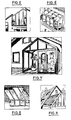
- Figures 5 to 9 show some examples of applications for corner brackets from the light metal extruded profile according to the invention.
- Figure 5 shows a detail in the gable wall of a house.
- This frame construction shows two miter corners in the upper area, which are equipped with such corner connectors.
- FIG. 6 shows a glass veranda with a large number of recurring miter-cut frame parts. In each of the mitred corners there is a corner bracket produced according to the invention. Glass verandas of this type can also be referred to as "solar extensions" with a suitable design.
- FIG. 7 shows a stem made of a glazed frame construction, which also has corner angles of the type according to the invention at its miter corners, which are present several times.
- Figure 8 shows a roof section with a glazed frame construction in the manner of a studio window. Profiles according to the invention are also used here on the forward-facing miter corners.
- Figure 9 shows an attached greenhouse, in the supporting frame profiles at the mitred corners are also provided according to the invention light metal extruded sections.
- the scope of application of the subject matter of the invention is far from exhausted with the exemplary embodiments shown.
- the tongues 3 and the grooves have complementary T-shaped cross sections and a corresponding spatial position.
- tongues and grooves are arranged several times (three times). As far as the reference numerals refer to the same parts or parts with the same function, they have been retained.
- the corner connectors according to the invention allow a wide range of screw fastenings with respect to the hollow profiles: the screw connections can be carried out optionally or simultaneously on the outside and / or inside of the miter corner and / or on the flat sides of the miter corner.
Landscapes
- Engineering & Computer Science (AREA)
- General Engineering & Computer Science (AREA)
- Mechanical Engineering (AREA)
- Civil Engineering (AREA)
- Structural Engineering (AREA)
- Mutual Connection Of Rods And Tubes (AREA)
- Blow-Moulding Or Thermoforming Of Plastics Or The Like (AREA)
- Mirrors, Picture Frames, Photograph Stands, And Related Fastening Devices (AREA)
Abstract
Description
- Die Erfindung betrifft einen Eckverbinder mit zwei unter einem von 180 Grad verschiedenen Winkel zueinander stehenden, in Hohlprofile mit von einem Rechteck umschriebenen Hohlraum einschiebbaren Schenkeln.
- Für die Herstellung von Eckverbindungen an auf Gehrung geschnittenen Hohlprofilen steht heute eine Vielzahl von im Kokillenguß hergestellten "Eckwinkeln" zur Verfügung, sofern es sich um kleinere Profilquerschnitte sowie um 90-Grad-Eckverbindungen handelt, wie sie im Fenster-und Türenbau überwiegend vorkommen. Derartige Eckwinkel erlauben es jedoch nicht, Eckverbindungen mit einem von 90 Grad abweichenden Winkel herzustellen oder gar Stoßverbindungen, d.h. die geradlinige Aneinanderreihung derartiger Hohlprofile.
- Für die Herstellung von Eckverbindungen mit einem von 90 Grad abweichenden Eckwinkel gibt es verstellbare Winkel, bei denen an die beiden Schenkel kreisscheibenförmige Platten angeformt sind, die in Bezug auf beide Schenkel abwechselnd ineinandergreifen und durch Schrauben gegeneinander verspannbar sind. Abgesehen davon, daß die statische Festigkeit derartiger "Gelenkwinkel" verhältnismäßig gering ist, verursacht auch die Ausrichtung der an der Gehrungsfuge spiegelsymmetrisch zusammenstossenden, identischen Hohlprofile Schwierigkeiten, weil nämlich wegen der im wesentlichen zylindrischen Außenform der Gelenkstelle ausgerechnet im Bereich der Gehrungsfuge jegliche Führung oder Abstützung für die Hohlprofile fehlt. Außerdem füllen die beiden Schenkel die rechteckigen Hohlräume, in die sie eingesteckt werden, nicht vollständig aus, so daß eine umständliche Befestigung durch Schrauben vorgenommen werden muß, deren Köpfe zudem auch noch von weitem sichtbar sind. Vor allem die Querstabilität derartiger "Gelenkwinkel" (gegen Winddruck) läßt zu wünschen übrig.
- Der Erfindung liegt daher die Aufgabe' zugrunde, einen Eckverbinder der eingangs beschriebenen Gattung anzugeben, mit dem Eckverbindungen nahezu beliebiger Winkelgrade herstellbar sind, die einer hohen Belastung in vertikaler und horizontaler Richtung standhalten.
- Die Lösung der gestellten Aufgabe erfolgt bei dem eingangs angegebenen Eckverbinder erfindungsgemäß dadurch, daß
- a) der Eckverbinder aus mindestens zwei an sich bebekannten Leichtmetall-Strangprofil-Abschnitten mit einer langen Querschnittsachse zusammengesetzt ist, bei denen an in Richtung der langen Querschnittsachse gegenüberliegenden, parallel zur Profillängsachse verlaufenden Stoßflächen auf der einen Seite mindestens eine hinterschnittene Nut und auf der anderen Seite mindestens eine in eine Nut gleicher Abmessungen unter Berührung an den Stoßflächen formschlüssig einführbare Feder angeordnet sind, und daß außerdem
- b) die Profilabschnitte zwei parallele, durch ebene Trennschnitte erzeigte Endflächen aufweisen, die unter einem von 90 Grad verschiedenen Winkel "ß" zur Profillängsachse verlaufen und wobei mindestens zwei Profilabschnitte .mit gleichem Winkel "ß" mittels der Nut des einen und der Feder des jeweils anderen Profilabschnitts "auf Umschlag" ineinander eingesetzt sind, derart, daß die Endflächen beider Profilabschnitte sich unter einem Winkel "2ß" paarweise' in einer Ebene - schneiden, in der die sich berührenden Stoßflächen der beiden Profilabschnitte liegen, derart, daß die ineinander eingesetzten Profilabschnitte die Schenkel des Eckverbinders sind.
- Ein derartiger Eckverbinder läßt sich leicht aus Strangprofilen entsprechenden Querschnitts durch ebene Trennschnitte herstellen, die senkrecht zu einer Symmetrieebene verlaufen, in der auch die Querschnittsachse des Profils liegt, die aber gleichzeitig unter einem entsprechenden Winkel zur Profillängsachse verlaufen. Die Profilabschnitte haben eine solche gleiche Länge, daß die Abstände zwischen den durch die Trennschnitte erzeugten Endflächen (immer in Normalenrichtung zu den Endflächen gesehen) der lichten Höhe des Hohlprofils entsprechen, so daß die betreffenden Profilabschnitte, nachfolgend kurz "Abschnitte" genannt, gerade eben in den Hohlraum des zugehörigen Hohlprofils einschiebbar sind. Es hängt dann nur von dem weiter oben beschriebenen Winkel für die Ausführung des Trennschnitts ab, welcher Gehrungswinkel zwischen den in der Gehrungsfuge aneinanderstossenden Hohlprofilen herstellbar ist. Die geometrischen Überlegungen für die Wahl des Winkels, unter dem die einzelnen Trennschnitte auszuführen sind, werden in der Detailbeschreibung näher erläutert.
- Es ist dann zur Herstellung des Eckverbinders lediglich erforderlich, in die Nut eines ersten Abschnitts die Feder eines "auf Umschlag gelegten" zweiten Abschnitts einzuschieben, so daß eine Feder-Nut-Verbindung entsteht, die auch als "Schwalbenschwanzführung" bezeichnet werden kann. Lediglich ein kleines Teilstück der Feder des ersten Abschnitts, das aus der Endfläche des zweiten Abschnitts auf einer Seite herausragt, muß noch abgetrennt werden.
- Es ist also lediglich erforderlich, ein Leichtmetall-Strangprofil mit dem erforderlichen Profilquerschnitt nach Festlegung eines vorgegebenen Trennwinkels in Abschnitte gleicher Länge zu unterteilen, um durch einfaches Zusammenschieben jeweils zweier, relativ zueinander "auf Umschlag gelegter" Abschnitte einen Eckverbinder herzustellen, der den erforderlichen Gehrungswinkel aufweist. Da ein solcher Eckwinkel auch bereits die exakte Lage der späteren Gehrungsfuge zwischen den Hohlprofilen festlegt (worauf weiter unten noch näher hingewiesen wird), werden für die relative Festlegung der beiden Abschnitte zueinander auch keine umständlichen Befestigungsmittel benötigt, da die Feder-Nut-Verbindung durch das übergeschobene Hohlprofil in axialer Richtung untrennbar, d.h. formschlüssig festgelegt wird. Eine zusätzliche Befestigung durch Stifte oder Schrauben oder durch Verkleben hat alsdann im Prinzip nur noch die Funktion einer Montagehilfe.
- Dabei sind die aneinanderstossenden Hohlräume der beiden Hohlprofile vom Querschnitt her stets voll ausgefüllt, d.h. insbesondere im Bereich der Gehrungsfuge wird eine gute Profilführung und damit ein absolut geschlossener Spalt erreicht. Damit wird die Verbindung auch gegenüber Querkräften (durch Winddruck) stabiler.
- Der Erfindungsgegenstand ermöglicht die Verbindung von Hohlprofilen mit nahezu beliebigen Höhenabmessungen, ohne daß es hierzu besonderer Verbindungselemente bedürfte. Bei der Verbindung von Hohlprofilen mit besonders großen Höhenabmessungen kann es zweckmäßig sein, an jedem Ende der bereits zu einem Eckverbinder zusammengesetzten Abschnitte noch ein oder mehrere identische Abschnitte geradlinig anzusetzen, so daß die durch die Trennschnitte erzeugten Endflächen der Profile innerhalb der gleichen Schenkel miteinander fluchten. Dies ist deswegen möglich, weil sich an den Enden der beiden Schenkel stets am Ende des einen Schenkels eine Feder und am Ende des anderen Schenkels eine Nut befindet. Auch diese zusätzlichen Feder-Nut-Verbindungen können nicht "aufgehen", da sie innerhalb des mit geringen Toleranzen aufgeschobenen Hohlprofils liegen, mit dem sie zusätzlich verklebt und/oder verschraubt werden.
- Unter dem Ausdruck "Hohlprofile" werden neben allseitig geschlossenen kastenförmigen Profilen auch solche verstanden, die einseitig offen sind (C-Profile) und Kastenprofile, die auf einer oder mehreren Seiten noch zusätzliche Profilvorsprünge aufweisen, beispielsweise solche, in die Fenster und andere Fassadenelemente eingesetzt werden können. Derartige Profile sind beispielhaft in dem Buch "Bauen mit Aluminium", 1983, Seiten 110 und 111, beschrieben.
- Es ist dabei besonders vorteilhaft, wenn Nut und Feder auf dem größten Teil ihres Umfangs von Zylinderflächen begrenzt sind. Auf diese Weise läßt sich eine sehr hohe Passgenauigkeit erzielen. Dabei ist vorzugsweise die Feder, ausgehend von ihrer Zylinderfläche, über einen Steg mit trapezförmigem Querschnitt mit dem übrigen Teil des Profils verbunden. Die auf der gegenüberliegenden Seite angeordnete Nut hat alsdann eine komplementäre Form.
- Auf die vorstehend angegebene Weise wird eine hohe Gestaltfestigkeit der Feder-Nut-Verbindung gegen Querkräfte erzielt, da diese Kräfte an den Stoßflächen aufgefangen werden, die in Bezug auf die gemeinsame Achse der Feder-Nut-Verbindung gewissermassen Hebelarme darstellen.
- Schließlich ist es von Vorteil, wenn das Profil entlang der Querschnittsachse A-A und spiegelsymmetrisch zu dieser eine Mindeswandstärke von 10 mm aufweist. Hierdurch wird ein Steg entsprechender Wandstärke gebildet, der zum Einbringen von Bohrungen und Gewinden für Befestigungsschrauben in beliebigen Abständen dient. Wegen der unter einem von 90 Grad abweichenden Winkel zur Profillängsachse verlaufenden Endflächen der einzelnen Profilabschnitte und der Notwendigkeit, die Schrauben in Normalenrichtung zu den schrägen Enflächen einzubringen, verlaufen die Schraubenachsen in aller Regel nicht parallel zur Profillängsachse. Infolgedessen können für diese Arte der Befestigung keine vorgefertigten Schraubenkanäle vorgesehen werden. Die angegebene Mindestwandstärke schafft aber die erforderliche Gestaltungsfreiheit. Insbesondere können dadurch die Schrauben bzw. die Schraubenköpfe an eine Stelle verlegt werden, die bei einer Seitenansicht des Profilrahmens nicht sichtbar ist.
- Eine besonders vorteilhafte Ausführungsform des Erfindungsgegenstandes ist dadurch gekennzeichnet, daß Feder und Nut>durch einen die Mindestwandstärke aufweisenden Steg miteinander verbunden sind, von dem im Bereich der Feder und der Nut paarweise Flansche ausgehen, deren der Feder zugewandte bzw. in die Nut einmündende Oberflächenteile die weiter oben beschriebenen Stoßflächen für die Anlage eines jeweils weiteren Profilabschnitts darstellen. Die Flanschen stellen dabei die Hebelarme für die weiter oben beschriebene Abstützung dar, und die Stoßflächen verlaufen bevorzugt senkrecht zur Querschnittsachse A-A.
- Die von der Querschnittsachse A-A jeweils nach außen weisenden Oberflächenteile der Flansche haben dabei ganz besonders zweckmäßigerweise einen Abstand B, der dem lichten Maß der Breite des im Profil vorhandenen Hohlraums entspricht. Auf diese Weise füllen die Flansche wenigstens stellenweise den gesamten Innenquerschnitt der Hohlräume der zu verbindenden Hohlprofile aus, und zwar insbesondere in unmittelbarer Nähe der Gehrungsfuge, so daß eine ausgezeichnete Führung der Hohlprofile in der Gehrungsfuge gewährleistet ist.
- Es ist dabei weiterhin ganz besonders zweckmäßig, wenn zwischen den Flanschen in der Mitte des Steges Distanzrippen angeordnet sind, und wenn die jeweils von der Querschnittsachse A-A nach außen weisenden Oberflächenteile der Flansche und der Distanzrippen auf jeder Seite des Steges in je einer gemeinsamen Ebene Ei bzw. E2 enden, die parallel zur Querschnittsachse A-A verlaufen.
- Auf die vorstehend angegebene Weise lassen sich die Schenkel des Eckverbinders großflächig mit den langen Seitenwänden der Hohlprofile verkleben. Die Klebeverbindung wird dadurch weiter ' begünstigt, wenn die nach außen weisenden, in den Ebenen E, und E2 liegenden Oberflächen der Flanschen und der Distanzrippen mit einer Mikroprofilierung versehen sind. Bei dieser Mikroprofilierung handelt es sich um dreieckförmige Rippen, die durch ebensolche Nuten voneinander getrennt sind, wobei die Tiefe der Riffelung zwischen 0,2 und 0,4 mm liegen kann und der Flankenwinkel 90 Grad beträgt.
- Der vorstehend beschriebene Eckverbinder ermöglicht die Herstellung von Eckverbindungen, bei denen Hohlprofile unter den unterschiedlichsten Winkeln zwischen 90 Grad und fast 180 Grad zueinander ausgerichtet sein können. Dies wird dadurch ermöglicht, daß die beiden, durch einen Trennschnitt erzeugten ebenen Endflächen eines jeden Profilabschnitts unter einem Winkel β von fast 90 Grad bis 45 Grad zur Profillängsachse verlaufen. Bevorzugt eignet sich der Erfindungsgegenstand jedoch zur Herstellung von Eckverbindungen, bei denen die Hohlprofile Winkel zwischen 100 Grad und 160 Grad einschliessen. Dies wird dadurch ermöglicht, daß die Endflächen der Profilabschnitte unter einem Winkel β von 80 bis 50 Grad zur Profillängsachse verlaufen.
- Weitere vorteilhafte Ausgestaltungen und Verwendungen des Erfindungsgegenstandes werden einschließlich der damit verbundenen Vorteile in der nachfolgenden Detailbeschreibung näher erläutert.
- Ein Ausführungsbeispiel des Erfindungsgegenstandes wird nachfolgend anhand der Figuren 1 bis 10 näher erläutert.
- Es zeigen:
- Figur 1 einen Querschnitt durch ein Leichtmetall-Strangprofil für die Herstellung eines Eckverbinders,
- Figur 2 einen teilweisen Querschnitt durch eine Verbindungsstelle zweier Profile nach Figur 1,
- Figur 3 eine Seitenansicht des Profils nach Figur 1 in Richtung des Pfeils 111,
- Figur 4 einen Eckverbinder, hergestellt unter Verwendung zweier Abschnitte S1 und S2 aus Figur 3,
- Figuren 5 bis 9 Anwendungsbeispiele von Eckverbindern nach Figur 4 mit unterschiedlichen Eckwinkeln, und
- Figur 10 einen teilweisen Querschnitt durch ein anderes Ausführungsbeispiel einer Verbindungsstelle zweier Profile in einer analogen Darstellung wie in Figur 2.
- In Figur 1 ist ein Leichtmetall-Strangprofil 1 dargestellt, das eine lange Querschnittsachse A-A besitzt und zu dieser spiegelsymmetrisch ausgebildet ist. Die Profillängsachse verläuft senkrecht zur Zeichenebene, so daß durch die Querschnittsachse A-A und die Profillängsachse eine Symmetrieebene definiert wird, die gleichfalls senkrecht zur Zeichenebene verläuft. An den parallel zur Profillängsachse verlaufenden, in Richtung der Querschnittsachse A-A gegenüberliegenden Schmalseiten befindet sich auf der einen Seite eine hinterschnittene Nut 2 und auf der anderen Seite eine Feder 3, die in eine Nut gleicher Abmessungen wie die Nut 2 einführbar ist. Die Nut 2 und die Feder 3 sind auf dem größten Teil ihres Umfangs von Zylinderflächen 4 und 5 begrenzt. Die Feder 3 ist, ausgehend von ihrer Zylinderfläche 5, über einen Steg 6 mit trapezförmigem Querschnitt mit dem übrigen Teil des Profils verbunden. Feder und Nut sind komplementär zueinander ausgebildet, und dem trapezförmigen Steg 6 entspricht eine gleichfalls im Querschnitt trapezförmige Öffnung 7 der Nut 2. Es versteht sich, daß alle Übergänge gut abgerundet sind.
- In Bezug auf die Querschnittsachse A-A befinden sich beiderseits der Feder 3 Stoßflächen 8 und beiderseits der Nut 2 Stoßflächen 9, auf die im Zusammenhang mit Figur 2 noch näher eingegangen wird.
- Es wäre theoretisch möglich, den gesamten, zwischen den Stoßflächen 8 und 9 liegenden Raum mit der betreffenden Leichtmetall-Legierung auszufüllen. Aus Gewichtsgründen und zur Materialersparnis sind Feder und Nut jedoch nur durch einen Steg 10 verbunden, der aus den weiter oben angegebenen Gründen eine Mindestwandstärke von 10 mm aufweist. Im Bereich der Feder 3 ist ein Paar von Flanschen 11 angeordnet, während im Bereich der Nut 2 ein Paar von Flanschen 12 vorgesehen ist. Die der Feder 3 zugewandten Oberflächenteile der Flanschen 11 bilden die Stoßflächen 8, während die in die Nut 2 einmündenden Oberflächenteile der Stoßflächen 9 durchdie Flanschen 12 gebildet werden. Es ist zu erkennen, daß die Stoßflächen 8 und 9 jeweils senkrecht zur Querschnittsachse A-A verlaufen.
- Weiterhin ist in der Mitte des Steges 10, d.h. zwischen den Flanschen 11 und 12, in spiegelsymmetrischer Anordnung ein Paar von Distanzrippen 13 vorgesehen. Die jeweils von der Querschnittsachse A-A nach außen weisenden Oberflächenteile der Flanschen 11 und 12 und der Distanzrippen 13 liegen auf jeder Seite des Steges 10 in je einer gemeinsamen Ebene E, bzw. E2, die parallel zur Querschnittsachse A-A verlaufen, so daß die Stoßflächen 8 und 9 sowie die Ebenen E, und E2 ein Rechteck umreissen, dessen immaterielle Teile strichpunktiert dargestellt sind. Dieses Rechteck hat die Breite "B", die der lichten Innenbreite der zu verbindenden Hohlprofile entspricht. Die nach außen weisenden, in den Ebenen Ei und E2 liegenden Oberflächenteile der Flanschen 11 und 12 und der Distanzrippen 13 sind mit einer Mikroprofilierung "M" versehen, durch die die Verklebung mit dem jeweils aufgeschobenen Hohlprofilen verbessert wird.
- Wie aus Figur 1 weiterhin ersichtlich ist, sind in den Distanzrippen 13 in symmetrischer Anordnung beiderseits der Querschnittsachse A-A Schraubkanäle 14 angeordnet, die allerdings nur dann zum Einsatz kommen können, wenn die Endflächen der einzelnen Profilabschnitte senkrecht zur Profillängsachse verlaufen, d.h., wenn die Endflächen mit dem Profilquerschnitt identisch sind. In diesem Falle läßt sich aus zwei Profilen gemäß Figur 1 ein Stoß-Verbindungsstück für die geradlinige Verbindung von zwei Hohlprofilen herstellen, wobei die - schmalen Wände des Hohlprofils senkrecht zu den Achsen der Schraubkanäle 14 verlaufen. In diesem Fall läßt sich durch eine Schablone das Hohlprofil exakt über den Schraubkanälen 14 anbohren, so daß auf die angegebene Weise eine zuverlässige Schraubverbindung zwischen den Profilabschnitten und den Hohlprofilen herstellbar ist. Die Stoßstelle der Hohlprofile liegt dann exakt in der Ebene der Stoßflächen 8 bzw. 9.
- Zwischen den Flanschen 11 und den Distanzrippen 13 befinden sich weitere Längsnuten, deren Nutengründe 15 durch den Steg 10 gebildet werden. An beiden Enden eines jeden Nutengrundes 15 befindet sich je eine Hinterschneidung 16, in die ein weiteres, hier nicht gezeigtes, Befestigungselement eingeschoben werden kann, das einen komplementären, T-förmigen Querschnitt besitzt.
- Figur 2 zeigt eine Verbindungsstelle zweier Profilabschnitte S, und S2, die eine Feder-Nut-Verbindung 16 bilden. Die Achse der Feder 3 verläuft dabei ebenso senkrecht zur Zeichenebene wie die Flanschen 11 und 12 bzw. die zwischen Ihnen vorhandenen Stoßflächen 8 und 9 (Figur 1). Man kann sich die Achse der Feder-Nut-Verbindung 16 als eine Gelenkachse vorstellen, und es ist erkennbar, daß die Flanschen 11 und 12 der Verbindung ihre Festigkeit verleihen, wenn man sich beispielsweise ein auf die Verbindung 16 einwirkendes Drehmoment um die "Gelenkachse" vorstellt. Auf jeden der beiden Abschnitte Si und S2 ist ein Hohlprofil 17 bzw. 18 aufgeschoben, deren vertikale Wandflächen im Schnitt und schraffiert dargestellt sind, während die horizontal oder geneigt verlaufenden (schmaleren) Wandflächen 17a bzw. 18a in der Draufsicht gezeigt sind. Die Stoß-bzw. Gehrungsfuge C-C, in der die beiden Hohlprofile 17 und 18 aneinanderstossen, verläuft gleichfalls senkrecht zur Zeichenebene, so daß die betreffende Fuge in der gleichen Ebene liegt wie die Stoßflächen 8 und 9 (Figur 1).
- Es ist insbesondere Figur 2 zu entnehmen, daß die Flanschen 11 und 12 den Querschnitt der Hohlprofile 17 und 18 vollständig ausfüllen. Dadurch werden nicht nur die genannten Hohlprofile im Bereich der Gehrungsfuge zuverlässig geführt und exakt aufeinander ausgerichtet, sondern das Hohlprofil 17 verhindert gemäß Figur 2 auch eine Aufweitung des äußeren Teils (Nut 2) der Feder-Nut-Verbindung 16 durch sehr große Kräfte. Es ist weiterhin zu erkennen, daß die Feder 3 des Abschnitts S2 in den Hohlraum des Hohlprofils 17 hineinragt, so daß sie auf diese Weise durch das Hohlprofil 17 an einem Herausschieben aus der Nut zuverlässig gehindert wird.
- In der Draufsicht auf die Verbindungsstelle in Figur 2 existiert im Bereich der Linie C-C eine Art "Dachfirst", d.h. die beiden oberen Endflächen der Abschnitte Si und S2 haben in Bezug auf die Gehrungsfuge C-C ein spiegelsymmetrisches Gefälle (siehe auch Figur 4).
- Figur 3 zeigt (unter Verwendung bisheriger Bezugszeichen) eine Draufsicht auf das Profil 1 in Richtung des Pfeils 111 in Figur 1. Hierbei verläuft die Symmetrieebene des Profils (Querschnittsachse A-A) parallel zur Zeichenebene. In dieser Lage wird das Profil auf einer Unterlage gehalten, wenn es in einzelne Abschnitte Si bis S4 zerlegt wird.
- Die parallelen Trennschnitte bzw. Endflächen der einzelnen Abschnitte verlaufen infolgedessen stets senkrecht zu der genannten Symmetrieebene, aber gleichzeitig unter einem Winkel "ß" zur Profillängsachse. Der Komplementärwinkel zum Profilquerschnitt Q-Q ist infolgedessen "a". Auf diese Weise entstehen in der Draufsicht Profilabschnitte mit rhombusförmigen Umrißlinien, deren Höhe (gemessen in Richtung der gestrichelten Linien) dem inneren lichten Höhenmaß des aufzuschiebenden Hohlprofils entspricht. Der Winkel"ß"ist je nach dem geforderten Gehrungswinkel zwischen 90 Grad und 45 Grad (gegebenenfalls auch darunter) frei wählbar. Es ist allerdings darauf zu achten, daß das Maß D für die Überlappung der Endflächen der Abschnitte (gemessen zwischen den gestrichelten Linien) ausreichend groß ist. Bei großer Höhe des Hohlprofils und/oder spitzem Gehrungswinkel wird die Überlappung D zunehmend kleiner. In diesem Fall können, wie bereits weiter oben ausgeführt wurde, zwei (oder mehrere) Abschnitte unter Verwendung ihrer Feder-Nut-Verbindungen 16 geradlinig aneinander gereiht werden, wodurch sich das Maß D der Überlappung entsprechend vervielfacht.
- Figur 4 zeigt nun, in welcher Weise die beiden Abschnitte S1 und S2 aus Figur 3 nach Herumlegen des Abschnitts S1 "auf Umschlag" miteinander zu vereinigen sind, um einen Eckwinkel zu erhalten. Die Federn 3 sind dabei jeweils nach rechts gerichtet, die Nuten 2 nach links. Es ist anhand der gestrichelten Linien erkennbar, daß zunächst die Feder 3 des linken Abschnitts Si um ein kurzes Stück 3a aus der oberen Endfläche 19 des Abschnitts S2 herausragt. Dieses Stück wird alsdann einfach abgetrennt. Nach dem Verbinden der Abschnitte S1 und S2 werden diese relativ zueinander festgelegt, was durch Verkleben, eine Schraub-oder Quetschverbindung erfolgen kann. Es ist zu erkennen, daß sich in dem gemäß Figur 4 zusammengesetzten Zustand der beiden Abschnitte S. und S2 die Endflächen 19 bzw. 20 der beiden Abschnitte paarweise in derjenigen Ebene schneiden, in der die sich berührenden Stoßflächen 8 und 9 der beiden Abschnitte liegen (siehe hierzu auch Figur 2, Linie C-C). Die Endflächen 19 und 20 bilden hierbei eine Art Dachfläche mit einer Firstlinie an der Stelle der sich berührenden Stoßflächen. Der dazwischen eingeschlossene Winkel "ist der sogenannte Gehrungswinkel, und zwar ist
 = 2 x ß, und insgesamt gilt 2 x α +
 = 180 Grad. Daraus ergibt sich auch, daß die jeweils zusammengehörigen Endflächen 19 und 20 der beiden Abschnitte S1 und S2 bei einer von 90 Grad abweichenden Lage dieser Endflächen zur Profillängsachse in Ebenen liegen, die spiegelsymmetrisch zu derjenigen Ebene verlaufen, in der sich die Stoßflächen 8 und 9 der Abschnitte Si und S2 berühren.
- Auf einen solchermaßen hergestellten Eckwinkel lassen sich dann die Hohlprofile 17 und 18 einfach aufschieben und in der weiter oben angegebenen Weise mit dem Eckwinkel verbinden.
- Befestigungsbeispiele mit Schraubverbindungen sind in Fig. 4 gleichfalls gezeigt: Die stets senkrecht zur zugehörigen Oberfläche ausgerichteten Schraubenachsen ai , a2 und a3 haben die Abstände di , d2 und d3 von der Gehrungsfuge (Linie C-C). Diese Abstände sind stets gleich, und zwar unabhängig von den Winkeln a , ß und. Dies ist wichtig im Hinblick auf die Vorratshaltung von Bohrschablonen.

- Die Figuren 5 bis 9 zeigen einige Anwendungsbeispiele für Eckwinkel aus dem erfindungsgemäßen Leichtmetall-Strangprofil. So zeigt Figur 5 einen Ausschnitt in der Giebelwand eines Hauses. In dem Ausschnitt befindet sich eine Rahmenkonstruktion mit Verglasung, hinter der sich ein Dachgarten befindet. Diese Rahmenkonstruktion zeigt im oberen Bereich zwei Gehrungsecken, die mit derartigen Eckverbindern ausgerüstet sind, Figur 6 zeigt eine Glasveranda mit einer Vielzahl von wiederkehrenden, auf Gehrung geschnittenen Rahmenteilen. In jeder der Gehrungsecken befindet sich ein erfindungsgemäß hergestellter Eckwinkel. Derartige Glasveranden können bei geeigneter Gestaltung auch als "Solaranbauten" bezeichnet werden.
- Figur 7 zeigt einen Vorbau aus einer verglasten Rahmenkonstruktion, die an ihren mehrfach vorhandenen Gehrungsecken gleichfalls Eckwinkel der erfindungsgemäßen Art besitzt. Figur 8 zeigt einen Dachausschnitt mit einer verglasten Rahmenkonstruktion nach Art eines Atelierfensters. Auch hier werden an den nach vorn weisenden Gehrungsecken erfindungsgemäße Profile verwendet. Figur 9 zeigt ein angebautes Gewächshaus, in dessen tragenden Rahmenprofilen an den Gehrungsecken gleichfalls erfindungsgemäße Leichtmetall-Strangprofilabschnitte vorgesehen sind. Mit den dargestellten Ausführungsbeispielen ist jedoch die Anwendungsbreite des Erfindungsgegenstandes bei weitem nicht erschöpft.
- Es ist natürlich auch möglich, die Anzahl der komplementären Federn und Nuten an beiden Schmalseiten des Profilquerschnitts zu vervielfachen, um die Gestaltfestigkeit noch weiter zu erhöhen.
- Bei der Variante der Feder-Nut-Verbindung 16 nach Fig. 10 haben die Federn 3 und die Nuten komplementäre T-förmige Querschnitte und eine entsprechende räumliche Lage. Außerdem sind Federn und Nuten jeweils mehrfach (dreifach) angeordnet. Soweit die Bezugszeichen gleiche Teile oder Teile mit gleicher Funktion betreffen, wurden sie beibehalten.
- Die erfindungsgemäßen Eckverbinder lassen eine große Variationsbreite von Schraubbefestigungen gegenüber den Hohlprofilen zu: Die Verschraubungen können wahlweise oder gleichzeitig auf der Außen-und/oder Innenseite der Gehrungsecke und/oder auf den Flachseiten der Gehrungsecke erfolgen.
Claims (7)
Priority Applications (1)
| Application Number | Priority Date | Filing Date | Title |
|---|---|---|---|
| AT87113373T ATE61087T1 (de) | 1986-09-22 | 1987-09-12 | Eckverbinder fuer hohlprofile. |
Applications Claiming Priority (2)
| Application Number | Priority Date | Filing Date | Title |
|---|---|---|---|
| DE19863632154 DE3632154A1 (de) | 1986-09-22 | 1986-09-22 | Leichtmetall-strangprofil, insbesondere fuer die herstellung von eck- und stossverbindungen |
| DE3632154 | 1986-09-22 |
Publications (2)
| Publication Number | Publication Date |
|---|---|
| EP0261532A1 true EP0261532A1 (de) | 1988-03-30 |
| EP0261532B1 EP0261532B1 (de) | 1991-02-27 |
Family
ID=6310074
Family Applications (1)
| Application Number | Title | Priority Date | Filing Date |
|---|---|---|---|
| EP87113373A Expired - Lifetime EP0261532B1 (de) | 1986-09-22 | 1987-09-12 | Eckverbinder für Hohlprofile |
Country Status (3)
| Country | Link |
|---|---|
| EP (1) | EP0261532B1 (de) |
| AT (1) | ATE61087T1 (de) |
| DE (2) | DE3632154A1 (de) |
Cited By (1)
| Publication number | Priority date | Publication date | Assignee | Title |
|---|---|---|---|---|
| AT411094B (de) * | 2001-09-03 | 2003-09-25 | Vinzenz Harrer | Steckverbindung |
Families Citing this family (4)
| Publication number | Priority date | Publication date | Assignee | Title |
|---|---|---|---|---|
| DE4136499A1 (de) * | 1991-11-06 | 1993-05-13 | Schueco Int Kg | Eckverbinder fuer hohlprofile eines fensters, einer tuer, einer fassade oder dergleichen |
| DE9206625U1 (de) * | 1992-05-15 | 1993-09-16 | Niemann, Hans Dieter, 50169 Kerpen | Verbindung für winklig aneinanderstoßende Hohlprofilstäbe |
| DE4225917C2 (de) * | 1992-08-05 | 1996-04-11 | Thyssen Polymer Gmbh | Rahmen-Verbundsystem |
| DE4316063C1 (de) * | 1993-05-13 | 1994-08-18 | Gerd Philippi | Pyramidenförmiges Dachgerüst für ein Glasdach |
Citations (5)
| Publication number | Priority date | Publication date | Assignee | Title |
|---|---|---|---|---|
| US3099051A (en) * | 1960-05-31 | 1963-07-30 | Case Jamb Inc | Corner reinforcing and adjusting means for frames |
| DE1904908A1 (de) * | 1968-01-31 | 1969-10-02 | Skipp Kenneth Valentine | Verbindungsstuecke fuer Profilteile od.dgl.und Verfahren zur Herstellung derselben |
| DE1943342A1 (de) * | 1969-08-26 | 1971-03-04 | Kabel Metallwerke Ghh | Anordnung zur Verbindung winklig aneinanderstossender Hohlprofile,z.B. Handlaeufe eines Gelaenders aus Leichtmetall |
| DE2600785A1 (de) * | 1975-01-10 | 1976-07-15 | Adolf Damgaard | Verkleidungen fuer tuer- oder fensteroeffnungen |
| EP0126410A2 (de) * | 1983-05-21 | 1984-11-28 | Edwin Röder | Riegel-Stielverbindung durch ein zweiteiliges Verbindungselement |
Family Cites Families (3)
| Publication number | Priority date | Publication date | Assignee | Title |
|---|---|---|---|---|
| CH345256A (de) * | 1956-08-20 | 1960-03-15 | Menziken Aluminium Ag | Profilleiste, eingerichtet zum Anfügen an eine andere gleiche Leiste |
| DE1919273U (de) * | 1964-12-15 | 1965-07-08 | Gustav Siegbert | Brettartiger hohlstab als bauelement aus kunststoff. |
| DE3412004C2 (de) * | 1984-03-31 | 1987-02-12 | Wieland-Werke Ag, 7900 Ulm | Eck- oder Stoßverbindung von Hohlprofilen für Fenster, Türen, Fassaden od. dgl. |
-
1986
- 1986-09-22 DE DE19863632154 patent/DE3632154A1/de active Granted
-
1987
- 1987-09-12 EP EP87113373A patent/EP0261532B1/de not_active Expired - Lifetime
- 1987-09-12 DE DE8787113373T patent/DE3768188D1/de not_active Expired - Lifetime
- 1987-09-12 AT AT87113373T patent/ATE61087T1/de not_active IP Right Cessation
Patent Citations (5)
| Publication number | Priority date | Publication date | Assignee | Title |
|---|---|---|---|---|
| US3099051A (en) * | 1960-05-31 | 1963-07-30 | Case Jamb Inc | Corner reinforcing and adjusting means for frames |
| DE1904908A1 (de) * | 1968-01-31 | 1969-10-02 | Skipp Kenneth Valentine | Verbindungsstuecke fuer Profilteile od.dgl.und Verfahren zur Herstellung derselben |
| DE1943342A1 (de) * | 1969-08-26 | 1971-03-04 | Kabel Metallwerke Ghh | Anordnung zur Verbindung winklig aneinanderstossender Hohlprofile,z.B. Handlaeufe eines Gelaenders aus Leichtmetall |
| DE2600785A1 (de) * | 1975-01-10 | 1976-07-15 | Adolf Damgaard | Verkleidungen fuer tuer- oder fensteroeffnungen |
| EP0126410A2 (de) * | 1983-05-21 | 1984-11-28 | Edwin Röder | Riegel-Stielverbindung durch ein zweiteiliges Verbindungselement |
Cited By (1)
| Publication number | Priority date | Publication date | Assignee | Title |
|---|---|---|---|---|
| AT411094B (de) * | 2001-09-03 | 2003-09-25 | Vinzenz Harrer | Steckverbindung |
Also Published As
| Publication number | Publication date |
|---|---|
| ATE61087T1 (de) | 1991-03-15 |
| DE3632154A1 (de) | 1988-04-07 |
| EP0261532B1 (de) | 1991-02-27 |
| DE3768188D1 (de) | 1991-04-04 |
| DE3632154C2 (de) | 1990-02-08 |
Similar Documents
| Publication | Publication Date | Title |
|---|---|---|
| DE3920353A1 (de) | Geruest fuer einen schaltschrank aus mehrfach abgewinkelten profilelementen mit einseitig offenem hohlprofil | |
| EP0526873A1 (de) | Profilverbindung, insbesondere für Aluminium-Leichtbau | |
| DE3415344A1 (de) | Schnellbaugerippe, insbesondere aus stahl als tragende konstruktion fuer decken- und wandplatten eines gebaeudes | |
| EP0825322B1 (de) | Gehrungseckverbindung für aus Hohlprofilstäben zusammengesetzte Rahmenteile | |
| DE2313041A1 (de) | Mit einem gleichartigen zu einem geschlossenen kastenprofil zusammensteckbares profil | |
| DE3621408C2 (de) | ||
| DE9406655U1 (de) | Verbindungsstück für winklig aneinanderstoßende Hohlprofilstäbe | |
| DE3728247C1 (de) | Verbundprofil fuer Rahmenschenkel oder Sprossen | |
| DE9116873U1 (de) | Verbindungsvorrichtung für eine Sprossenkreuzkonstruktion | |
| EP0058376B1 (de) | Verbindung für ineinandergreifende Metall- oder Kunststoffprofile | |
| DE9409382U1 (de) | Fassadenkonstruktion für Gebäude | |
| EP0261532B1 (de) | Eckverbinder für Hohlprofile | |
| DE2615891C2 (de) | ||
| DE2609388B2 (de) | Stabilisierungs- und Ausrichtelement für Gehrungsstöße zwischen zwei Bauprofilen | |
| EP1643049A2 (de) | Tragprofilkonstruktion | |
| EP0799945A1 (de) | Pfosten-Sprossen-Konstruktion | |
| DE3241424A1 (de) | Verbindungseinrichtung | |
| WO1986005667A1 (fr) | Materiau profile creux pour chassis et cadres | |
| EP0111185A2 (de) | Rahmen, insbesondere für eine Duschtrennwand | |
| EP0540982B1 (de) | Eckverbinder für Hohlprofile eines Fensters, einer Tür, einer Fassade od.dgl. | |
| DE2654590C2 (de) | Gestell für elektrische Schaltanlagen | |
| DE60000604T2 (de) | Endverschlusskappe für Rolladenkasten | |
| EP0304830A2 (de) | Rahmen aus miteinander verbundenen Tragprofilabschnitten aus Holz, Kunststoff oder einem Verbundwerkstoff | |
| DE3625645C1 (en) | Wall structural element | |
| DE8617042U1 (de) | Anschluß eines Riegels an einen Pfosten einer Rahmen-Konstruktion |
Legal Events
| Date | Code | Title | Description |
|---|---|---|---|
| PUAI | Public reference made under article 153(3) epc to a published international application that has entered the european phase |
Free format text: ORIGINAL CODE: 0009012 |
|
| AK | Designated contracting states |
Kind code of ref document: A1 Designated state(s): AT BE CH DE FR IT LI LU NL |
|
| 17P | Request for examination filed |
Effective date: 19880827 |
|
| 17Q | First examination report despatched |
Effective date: 19890216 |
|
| GRAA | (expected) grant |
Free format text: ORIGINAL CODE: 0009210 |
|
| ITF | It: translation for a ep patent filed | ||
| AK | Designated contracting states |
Kind code of ref document: B1 Designated state(s): AT BE CH DE FR IT LI LU NL |
|
| REF | Corresponds to: |
Ref document number: 61087 Country of ref document: AT Date of ref document: 19910315 Kind code of ref document: T |
|
| REF | Corresponds to: |
Ref document number: 3768188 Country of ref document: DE Date of ref document: 19910404 |
|
| ET | Fr: translation filed | ||
| PLBI | Opposition filed |
Free format text: ORIGINAL CODE: 0009260 |
|
| PLBI | Opposition filed |
Free format text: ORIGINAL CODE: 0009260 |
|
| 26 | Opposition filed |
Opponent name: W. HARTMANN & CO (GMBH & CO), Effective date: 19911105 |
|
| 26 | Opposition filed |
Opponent name: SCHUECO INTERNATIONAL GMBH & CO. Effective date: 19911123 Opponent name: W. HARTMANN & CO (GMBH & CO), Effective date: 19911105 |
|
| NLR1 | Nl: opposition has been filed with the epo |
Opponent name: W. HARTMANN & CO (GMBH & CO) |
|
| NLR1 | Nl: opposition has been filed with the epo |
Opponent name: SCH CO INTERNATIONAL GMBH & CO |
|
| EPTA | Lu: last paid annual fee | ||
| PLBN | Opposition rejected |
Free format text: ORIGINAL CODE: 0009273 |
|
| STAA | Information on the status of an ep patent application or granted ep patent |
Free format text: STATUS: OPPOSITION REJECTED |
|
| 27O | Opposition rejected |
Effective date: 19950413 |
|
| NLR2 | Nl: decision of opposition | ||
| PGFP | Annual fee paid to national office [announced via postgrant information from national office to epo] |
Ref country code: AT Payment date: 20040830 Year of fee payment: 18 |
|
| PG25 | Lapsed in a contracting state [announced via postgrant information from national office to epo] |
Ref country code: IT Free format text: LAPSE BECAUSE OF NON-PAYMENT OF DUE FEES Effective date: 20050912 Ref country code: AT Free format text: LAPSE BECAUSE OF NON-PAYMENT OF DUE FEES Effective date: 20050912 |
|
| APAH | Appeal reference modified |
Free format text: ORIGINAL CODE: EPIDOSCREFNO |
|
| PGFP | Annual fee paid to national office [announced via postgrant information from national office to epo] |
Ref country code: DE Payment date: 20051019 Year of fee payment: 19 |
|
| PGFP | Annual fee paid to national office [announced via postgrant information from national office to epo] |
Ref country code: FR Payment date: 20051020 Year of fee payment: 19 |
|
| PGFP | Annual fee paid to national office [announced via postgrant information from national office to epo] |
Ref country code: CH Payment date: 20051024 Year of fee payment: 19 Ref country code: BE Payment date: 20051024 Year of fee payment: 19 |
|
| PGFP | Annual fee paid to national office [announced via postgrant information from national office to epo] |
Ref country code: NL Payment date: 20051025 Year of fee payment: 19 Ref country code: LU Payment date: 20051025 Year of fee payment: 19 |
|
| PG25 | Lapsed in a contracting state [announced via postgrant information from national office to epo] |
Ref country code: LI Free format text: LAPSE BECAUSE OF NON-PAYMENT OF DUE FEES Effective date: 20060930 Ref country code: CH Free format text: LAPSE BECAUSE OF NON-PAYMENT OF DUE FEES Effective date: 20060930 Ref country code: BE Free format text: LAPSE BECAUSE OF NON-PAYMENT OF DUE FEES Effective date: 20060930 |
|
| PG25 | Lapsed in a contracting state [announced via postgrant information from national office to epo] |
Ref country code: NL Free format text: LAPSE BECAUSE OF NON-PAYMENT OF DUE FEES Effective date: 20070401 |
|
| PG25 | Lapsed in a contracting state [announced via postgrant information from national office to epo] |
Ref country code: DE Free format text: LAPSE BECAUSE OF NON-PAYMENT OF DUE FEES Effective date: 20070403 |
|
| REG | Reference to a national code |
Ref country code: CH Ref legal event code: PL |
|
| NLV4 | Nl: lapsed or anulled due to non-payment of the annual fee |
Effective date: 20070401 |
|
| REG | Reference to a national code |
Ref country code: FR Ref legal event code: ST Effective date: 20070531 |
|
| BERE | Be: lapsed |
Owner name: *KRAUS SIEGFRIED Effective date: 20060930 |
|
| PG25 | Lapsed in a contracting state [announced via postgrant information from national office to epo] |
Ref country code: FR Free format text: LAPSE BECAUSE OF NON-PAYMENT OF DUE FEES Effective date: 20061002 |
|
| PG25 | Lapsed in a contracting state [announced via postgrant information from national office to epo] |
Ref country code: LU Free format text: LAPSE BECAUSE OF NON-PAYMENT OF DUE FEES Effective date: 20060912 |