EP0261635A1 - Machine électrique tournante supraconductrice et son isolement thermique - Google Patents
Machine électrique tournante supraconductrice et son isolement thermique Download PDFInfo
- Publication number
- EP0261635A1 EP0261635A1 EP87113818A EP87113818A EP0261635A1 EP 0261635 A1 EP0261635 A1 EP 0261635A1 EP 87113818 A EP87113818 A EP 87113818A EP 87113818 A EP87113818 A EP 87113818A EP 0261635 A1 EP0261635 A1 EP 0261635A1
- Authority
- EP
- European Patent Office
- Prior art keywords
- stator
- rotor
- cryogenic
- enclosure
- air gap
- Prior art date
- Legal status (The legal status is an assumption and is not a legal conclusion. Google has not performed a legal analysis and makes no representation as to the accuracy of the status listed.)
- Granted
Links
- 238000009413 insulation Methods 0.000 title claims abstract description 13
- 238000004804 winding Methods 0.000 claims abstract description 9
- 239000001307 helium Substances 0.000 claims description 13
- 229910052734 helium Inorganic materials 0.000 claims description 13
- SWQJXJOGLNCZEY-UHFFFAOYSA-N helium atom Chemical compound [He] SWQJXJOGLNCZEY-UHFFFAOYSA-N 0.000 claims description 13
- 239000004020 conductor Substances 0.000 claims description 5
- 239000007789 gas Substances 0.000 claims description 4
- 239000000463 material Substances 0.000 claims description 4
- 238000002955 isolation Methods 0.000 claims description 2
- 238000007789 sealing Methods 0.000 abstract description 4
- 238000005192 partition Methods 0.000 description 6
- 230000003471 anti-radiation Effects 0.000 description 2
- 239000007788 liquid Substances 0.000 description 2
- 238000000034 method Methods 0.000 description 2
- 230000036961 partial effect Effects 0.000 description 2
- 239000000843 powder Substances 0.000 description 2
- 230000002829 reductive effect Effects 0.000 description 2
- 238000000926 separation method Methods 0.000 description 2
- 230000003068 static effect Effects 0.000 description 2
- 238000004891 communication Methods 0.000 description 1
- 238000009833 condensation Methods 0.000 description 1
- 230000005494 condensation Effects 0.000 description 1
- 238000013016 damping Methods 0.000 description 1
- 239000000835 fiber Substances 0.000 description 1
- 239000002657 fibrous material Substances 0.000 description 1
- 230000004907 flux Effects 0.000 description 1
- 239000006260 foam Substances 0.000 description 1
- 239000006261 foam material Substances 0.000 description 1
- 238000010438 heat treatment Methods 0.000 description 1
- 239000011810 insulating material Substances 0.000 description 1
- 230000000670 limiting effect Effects 0.000 description 1
- 230000004048 modification Effects 0.000 description 1
- 238000012986 modification Methods 0.000 description 1
- 238000010992 reflux Methods 0.000 description 1
- 230000000717 retained effect Effects 0.000 description 1
Images
Classifications
-
- H—ELECTRICITY
- H02—GENERATION; CONVERSION OR DISTRIBUTION OF ELECTRIC POWER
- H02K—DYNAMO-ELECTRIC MACHINES
- H02K55/00—Dynamo-electric machines having windings operating at cryogenic temperatures
- H02K55/02—Dynamo-electric machines having windings operating at cryogenic temperatures of the synchronous type
- H02K55/04—Dynamo-electric machines having windings operating at cryogenic temperatures of the synchronous type with rotating field windings
-
- Y—GENERAL TAGGING OF NEW TECHNOLOGICAL DEVELOPMENTS; GENERAL TAGGING OF CROSS-SECTIONAL TECHNOLOGIES SPANNING OVER SEVERAL SECTIONS OF THE IPC; TECHNICAL SUBJECTS COVERED BY FORMER USPC CROSS-REFERENCE ART COLLECTIONS [XRACs] AND DIGESTS
- Y02—TECHNOLOGIES OR APPLICATIONS FOR MITIGATION OR ADAPTATION AGAINST CLIMATE CHANGE
- Y02E—REDUCTION OF GREENHOUSE GAS [GHG] EMISSIONS, RELATED TO ENERGY GENERATION, TRANSMISSION OR DISTRIBUTION
- Y02E40/00—Technologies for an efficient electrical power generation, transmission or distribution
- Y02E40/60—Superconducting electric elements or equipment; Power systems integrating superconducting elements or equipment
Definitions
- the present invention relates to rotary electrical machines having a superconductive stator and rotor.
- the windings of the stator and the rotor are arranged in separate cryogenic chambers thermally insulated and separated by a volume of air gap under vacuum to reduce thermal gains as much as possible.
- Maintaining a high vacuum in the air gap requires rotating seals with excellent sealing which are very difficult to achieve in practice.
- the present invention aims to avoid the aforementioned difficulty by retaining a simple structure for the rotating machine.
- the rotary electrical machine according to the invention has a stator and a rotor with superconductive windings arranged in separate cryogenic chambers for the rotor and the stator, themselves placed in thermal isolation chambers separated by a low airgap volume. pressure which considerably simplifies the dynamic sealing problems encountered hitherto.
- the thermal insulation enclosure enclosing the stator cryogenic enclosure is separated from the airgap volume by a tubular partition fixed at the end to two static end flanges of the machine by means tolerating an axial expansion such as a joint. piston.
- This tubular partition can be waterproof, the thermal insulation enclosure of the stator being entirely under empty, or not waterproof, the thermal insulation enclosure of the stator then having an interior chamber containing the cryogenic enclosure, filled with a powder, fiber or foam material reducing the axial thermal conductivity, and an exterior vacuum chamber.
- the airgap volume can be delimited, on the rotor side, by a drum supporting a double archimedes screw tending when the rotor turns, to reflux the gases filling the airgap volume, towards the ends of the machine to evacuate them from the space separating the stator and rotor cryogenic chambers and limiting the heat input. It is advantageously filled with helium vapors at a pressure of 1 to 10 Pascals.
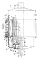
- the machine represented in FIG. 1 comprises three-phase stator windings 1 made of superconductive material and rotor windings 2 also superconductive. From the stator, three-phase conductors 1A leave towards a supply or an external use depending on whether the machine considered is used as a motor or an alternator.
- the rotor is carried by a rotating shaft 3. Its windings are connected to an external power supply by conductors 2A. Its periphery is separated from the stator by a volum e of air gap 4.
- a magnetic ring 5 made of laminated sheets preventing the magnetic flux from leaving the machine.
- the stator windings are arranged in a cryogenic enclosure 6 filled with 4.2 K helium, itself surrounded by a vacuum thermal insulation enclosure 7 in which is placed an antiradiation heat shield 8 formed for example of sheets reflective separated by insulating veils.
- Liquid helium is introduced into the stator cryogenic enclosure 6 through a conduit 9 and the helium vapors formed are evacuated through a conduit 10.
- the rotor windings are arranged in a cryogenic enclosure 11, itself surrounded by a vacuum thermal insulation enclosure 12.
- the helium circulates in the rotor cryogenic enclosure 11 in the liquid state, above its pressure critical, for example under 3.104 Pascals at 4.7 K and is introduced by a conduit 13 then evacuated after heating by a conduit 14 passing through the rotating shaft 3 and leaving the machine by a rotating connector for example of the Johnston type.
- stator and the rotor of the machine are contained in an envelope 15 provided with end plates 16, 17 on which are fixed bearings 18 supporting the shaft 3 of the rotor.
- the stator cryogenic enclosure 6 is fixed on one side to one of the end flanges 16 by means of a support tube 19 made of a material with low thermal conductivity and on the other side to the periphery of the envelope by to a system of columns not shown, damping vibrations.
- the vacuum thermal insulation enclosure 7 of the cryogenic stator enclosure 6 is connected by a conduit 20 to an external source of vacuum and is separated from the air gap volume 4 by a very thin sealed tube 21 dimensioned only to withstand the pressure of the air gap volume 4 and fixed at the end in a leaktight manner to the end flanges 16, 17 by means allowing axial expansion such as the piston seal which will be described later with reference to FIG. 4.
- the rotor cryogenic enclosure 11 is fixed inside a drum 22 delimiting the thermal insulation enclosure 12 which is under sealed vacuum.
- the air gap volume 4 is delimited, on the stator side, by the sealed tube 21 and, on the rotor side, by the rotating drum 22, and connected by a line 23 to a vacuum pump making it possible to maintain it under a low pressure of the order from 1 to 10 Pascals.
- annular chamber 24 filled with gaseous helium at a pressure slightly higher than atmospheric pressure by means of a supply pipe 25, 26 and sealed at the level of axis 3, of the rotor by two successive rotating joints 27, 28.
- the rotary joint 28 separating the air gap volume 4 from an intermediate chamber 24 is an oil seal holding to a low vacuum, followed by cold traps with oil vapors 29, 30 supplied by the stator and rotor cryogenic chambers 6 , 11.
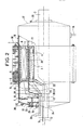
- FIG. 2 represents a variant of the machine represented in FIG. 1, which differs therefrom by the method of attachment of the stator cryogenic enclosure 6.
- the unmodified elements have retained their indexing in FIG. 1.
- the modification consists in supporting the stator cryogenic enclosure 6 directly by the sealed tube 21 ⁇ which defines the air gap volume 4 on the stator side.
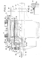
- FIG. 3 shows another variant of the machine represented in FIG. 1, which differs therefrom by the configuration of the thermal insulation enclosure of the stator cryogenic enclosure and by the method of attachment of the latter cryogenic enclosure.
- the unmodified elements have kept their indexing in FIG.
- the thermal insulation enclosure of the stator cryogenic enclosure 6 is divided into two concentric annular chambers 7 ⁇ and 7 ⁇ by a sealed tubular partition 40 fixed at the end to the two end flanges 16 and 17 of the envelope. 15 of the machine, the stator cryogenic enclosure 6 being supported, as in the previous variant by the tube 21 ⁇ delimiting the air gap volume 4 on the stator side.
- the inner concentric chamber 7 ⁇ which encloses the static cryogenic enclosure 6, is in communication with the airgap volume 4 by orifices 41 drilled through the wall of the separation tube 21 ⁇ , in the vicinity of its ends and is filled with '' a thermal insulating material in powder, fibers or foam avoiding thermal contributions by axial conduction through low pressure helium vapors.
- the outer concentric chamber 7 ⁇ is a vacuum chamber which encloses the anti-radiation thermal screen 8 and which avoids thermal contributions from outside the machine. It is connected by a 20 ⁇ conduit to a vacuum pump. Its structure is simplified by the fact that it is not crossed by electrical conductors or helium conduits since it is outside the cryogenic enclosure of the stator.
- the tubes 21 21 ⁇ , 21 ⁇ delimiting the air gap volume 4 as well as the tubular partition 40 are fixed at the end to an end flange 17 by example of the casing 15 so as to allow axial expansion by, for example, the use of a piston seal as shown in FIG. 4 for the tube 21.
- one of the end flanges 17 of the machine casing is provided internally with a circular edge 45 in which the end of the tube 21 fits with a slight clearance.
- An annular seal 46 disposed in a lateral groove 47 at the end of the circular edge 45 obstructs the clearance between the edge and the end of the tube when it is necessary to make a seal as in the case of tubes 21 and 21 ⁇ as well as the tubular partition 40 while flexible braids 48 made of a material that is a good conductor of heat connect the end flange 17 at the end of the tube 21 to ensure equalization of the temperatures and maintain the seal 46 at a sufficient temperature so that it retains its full effectiveness.
Landscapes
- Engineering & Computer Science (AREA)
- Power Engineering (AREA)
- Motor Or Generator Cooling System (AREA)
- Superconductive Dynamoelectric Machines (AREA)
- Superconductors And Manufacturing Methods Therefor (AREA)
- Inorganic Insulating Materials (AREA)
Abstract
Description
- La présente invention concerne des machines électriques tournantes ayant un stator et un rotor supraconducteurs.
- Dans ce genre de machine, les enroulements du stator et du rotor sont disposés dans des enceintes cryogéniques distinctes isolées thermiquement et séparées par un volume d'entrefer sous vide pour réduire au maximum les apports thermiques.
- Le maintien d'un vide poussé dans l'entrefer nécessite des joints tournants d'une excellente étanchéité très difficiles à réaliser en pratique.
- Pour tourner cette difficulté, il est connu par la demande de brevet français n o 2 372 535 de compléter les joints tournants, placés au voisinage des paliers supportant le rotor, par un système de pompe à vide formé de deux jeux concentriques de viroles à orifices, emboîtés l'un dans l'autre et solidaire l'un de la partie fixe, l'autre de la partie tournante du moteur. Cette disposition permet de réduire les performances d'étanchéité demandées au joints tournants en les plaçant en aval d'une pompe assurant le vide le plus poussé mais au prix d'une augmentation importante de la complexité de la structure de la machine au voisinage de ses paliers.
- La présente invention a pour but d'éviter la difficulté précitée en conservant une structure simple pour la machine tournante.
- La machine électrique tournante selon l'invention a un stator et un rotor à enroulements supraconducteurs disposés dans des enceintes cryogéniques distinctes pour le rotor et le stator, elles-mêmes placées dans des enceintes d'isolement thermique séparées par un volume d'entrefer à basse pression ce qui simplifie considérablement les problèmes d'étanchéité dynamique rencontrés jusqu'alors.
- L'enceinte d'isolement thermique renfermant l'enceinte cryogénique statorique est séparée du volume d'entrefer par une cloison tubulaire fixée en bout à deux flasques statiques d'extrémité de la machine grâce à des moyens tolérant une dilatation axiale tels qu'un joint à piston. Cette cloison tubulaire peut être étanche, l'enceinte d'isolement thermique du stator étant entièrement sous vide, ou non étanche, l'enceinte d'isolement thermique du stator présentant alors une chambre intérieure renfermant l'enceinte cryogénique, remplie d'un matériau en poudre, fibres ou mousse réduisant la conductibilité thermique axiale, et une chambre extérieure sous vide.
- Le volume d'entrefer peut être délimité, côté rotor, par un tambour supportant une double vis d'archimède tendant lorsque le rotor tourne, à refluer les gaz remplissant le volume d'entrefer, vers les extrémités de la machine pour les évacuer de l'espace séparant les enceintes cryogéniques statorique et rotorique et limiter les apports thermiques. Il est avantageusement rempli de vapeurs d'hélium à une pression de 1 à 10 Pascals.
- D'autres caractéristiques et avantages de l'invention ressortiront de la description ci-après d'exemples de réalisation. Cette description sera faite en regard du dessin dans lequel :
- - les figures 1, 2 et 3 sont des vues longitudinales, en coupe partielle, de machines selon l'invention et
- - la figure 4 est une coupe longitudinale partielle d'un élément de structure des machines représentée aux figures précédentes.
- La machine représentée à la figure 1 comporte des enroulements statoriques triphasés 1 en matériau supraconducteur et des enroulements rotoriques 2 également supraconducteurs. Du stator partent des conducteurs triphasés 1A vers une alimentation ou une utilisation extérieure selon que la machine considérée est utilisée en moteur ou en alternateur. Le rotor est porté par un arbre tournant 3. Ses enroulements sont reliés à une alimentation extérieure par des conducteurs 2A. Sa périphérie est séparée du stator par un volum e d'entrefer 4. Autour du stator est disposée une couronne magnétique 5 en tôles feuilletées enpêchant le flux magnétique de sortir de la machine.
- Les enroulements statoriques sont disposés dans une enceinte cryogénique 6 remplie d'hélium à 4,2 K, elle-même entourée d'une enceinte d'isolement thermique sous vide 7 dans laquelle est placé un écran thermique antiradiatif 8 formé par exemple de feuilles réfléchissantes séparées par des voiles isolants. L'hélium liquide est introduit dans l'enceinte cryogénique statorique 6 par un conduit 9 et les vapeurs d'hélium formées sont évacuées par un conduit 10.
- Les enroulements rotoriques sont disposés dans une enceinte cryogénique 11, elle-même entourée d'une enceinte d'isolement thermique sous vide 12. L'hélium circule dans l'enceinte cryogénique rotorique 11 à l'état liquide, au-dessus de sa pression critique, par exemple sous 3.10⁴ Pascals à 4,7 K et est introduit par un conduit 13 puis évacué après réchauffement par un conduit 14 passant dans l'arbre tournant 3 et sortant de la machine par un raccord tournant par exemple du type Johnston.
- L'ensemble des éléments du stator et du rotor de la machine sont contenus dans une enveloppe 15 pourvue de flasques d'extrémité 16, 17 sur lesquels sont fixés des paliers 18 supportant l'arbre 3 du rotor.
- L'enceinte cryogénique statorique 6 est fixée par un côté à l'un des flasques d'extrémité 16 au moyen d'un tube support 19 en un matériau à faible conductivité thermique et par l'autre côté à la périphérie de l'enveloppe grâce à un système de colonnettes non représenté, amortissant les vibrations.
- L'enceinte d'isolement thermique sous vide 7 de l'enceinte cryogénique statorique 6 est reliée par un conduit 20 à une source extérieure de vide et est séparée du volume d'entrefer 4 par un tube étanche 21 très mince dimensionné uniquement pour résister à la pression du volume d'entrefer 4 et fixé en bout de manière étanche aux flasques d'extrémités 16, 17 par des moyens permettant la dilatation axiale tels que le joint à piston qui sera décrit ultérieurement en regard de la figure 4.
- L'enceinte cryogénique rotorique 11 est fixée à l'intérieur d'un tambour 22 délimitant l'enceinte d'isolement thermique 12 qui est sous vide scellé.
- Le volume d'entrefer 4 est délimité, côté stator, par le tube étanche 21 et, côté rotor, par le tambour tournant 22, et relié par une conduite 23 à une pompe à vide permettant de le maintenir sous une faible pressin de l'ordre de 1 à 10 Pascals.
- Il est séparé de l'atmosphère ambiante, à chaque extrémité de l'axe 3 du rotor, par une chambre annulaire intermédiaire 24 remplie d'hélium gazeux à une pression légèrement supérieure à la pression atmosphérique grâce à une conduite d'amenée 25, 26 et rendu étanche au niveau de l'axe 3, du rotor par deux joints tournants successifs 27, 28.
- Le joint tournant 28 séparant le volume d'entrefer 4 d'une chambre intermédiaire 24 est un joint à huile tenant à un vide peu poussé, suivi de pièges froids à vapeurs d'huile 29, 30 alimentés par les enceintes cryogéniques statorique et rotorique 6, 11.
- Le remplissage du volume d'entrefer 4 par de l'hélium gazeux évite toute condensation sur la partie du tambour 22 en contact avec l'enceinte cryogénique rotorique 11. Les apports caloriques à ce niveau, engendrés par les pertes par frottement dues à la présence des vapeurs d'hélium dans le volume d'entrefer 4 sont diminués de deux manières d'une part, grâce à un filet 31 gravé en relief sur le tambour tournant 22 selon une double vis d'archimède qui tend à entraîner le gaz d'hélium vers les extrémités du volume d'entrefer 4 et d'autre part, grâce à des points froids 32, 33 placés de part et d'autre des enceintes cryogéniques statorique 6 et rotorique 11, à l'extérieur du tube 21 et à l'intérieur du tambour tournant 22.
- La figure 2 représente une variante de la machine représentée à la figure 1, qui en diffère par le mode de fixation de l'enceinte cryogénique statorique 6. Sur cette figure 2, les éléments non modifiés ont conservé leur indexation de la figure 1.
- La modification consiste à faire supporter l'enceinte cryogénique statorique 6 directement par le tube étanche 21ʹ qui délimite le volume d'entrefer 4 côté stator. Cela permet de supprimer le tube support spécial qui fixait l'un des côtés de l'enceinte statorique 6 à un flasque d'extrémité 16 de la machine ainsi que le système de fixation à colonnettes solidarisant l'autre côté de l'enceinte cryogénique statorique 6 avec la périphérie de l'enveloppe 15 de la machine. En éliminant ces pièces, on diminue les apports thermiques à l'enceinte cryogénique statorique 6 en provenance de l'extérieur avec, en contrepartie, une protection moindre à l'encontre des apports thermiques par conduction gazeuse dans le volume d'entrefer 4 et la nécessité de renforcer le tube étanche 21.
- La figure 3 représente une autre variante de la machine représentée à la figure 1, qui en diffère par la configuration de l'enceinte d'isolement thermique de l'enceinte cryogénique statorique et par le mode de fixation de cette dernière enceinte cryogénique. Comme précédemment, les éléments non modifiés ont conservé leur indexation de la figure 1.
- Dans cette variante, l'enceinte d'isolement thermique de l'enceinte cryogénique statorique 6 est partagée en deux chambres annulaires concentriques 7ʹ et 7ʺ par une cloison tubulaire étanche 40 fixée en bout aux deux flasque d'extrémité 16 et 17 de l'enveloppe 15 de la machine, l'enceinte cryogénique statorique 6 étant supportée, comme dans la variante précédente par le tube 21ʺ délimitant le volume d'entrefer 4 côté stator.
- La chambre concentrique intérieure 7ʹ, qui renferme l'enceinte cryogénique statique 6, est en communication avec le volume d'entrefer 4 par des orifices 41 percés au travers de la paroi du tube de séparation 21ʺ, au voisinage de ses extrémités et est remplie d'un matériau isolant thermique en poudre, fibres ou mousse évitant les apports thermiques par conduction axiale au travers des vapeurs d'hélium basse pression.
- La chambre concentrique extérieure 7ʺ est une chambre sous vide qui renferme l'écran thermique antiradiatif 8 et qui évite les apports thermiques de l'extérieur de la machine. Elle est reliée par un conduit 20ʹ à une pompe à vide. Sa structure est simplifiée du fait qu'elle n'est pas traversée par des conducteurs électriques ou des conduits d'hélium puisqu'elle est extérieure à l'enceinte cryogénique du stator.
- Des points froids 32 et 32ʹ alimentés par l'enceinte cryogénique statorique 4 et placés de part et d'autre de cette dernière, dans la chambre concentrique intérieure 7ʹ, contre la cloison tubulaire 40 et le tube de séparation 21ʺ, récupèrent l'enthalpie des vapeurs d'hélium basse pression issues de l'enceinte cryogénique statorique 6, par un système non représenté sur la figure.
- Dans les machines qui viennent d'être décrites, les tubes 21 21ʹ, 21ʺ délimitant le volume d'entrefer 4 ainsi que la cloison tubulaire 40 sont fixés en bout à un flasque d'extrémité 17 par exemple de l'enveloppe 15 de manière à permettre une dilatation axiale grâce par exemple à l'emploi d'un joint à piston comme représenté à la figure 4 pour le tube 21.
- Comme cela est visible sur la figure 4, l'un des flasques d'extrémité 17 de l'enveloppe de la machine est pourvu intérieurement d'une arête circulaire 45 dans laquelle s'emboîte avec un léger jeu l'extrémité du tube 21. Un joint annulaire 46 disposé dans une gorge latérale 47 à l'extrémité de l'arête circulaire 45 obstrue le jeu entre l'arête et l'extrémité du tube lorsqu'il est nécessaire de réaliser une étanchéité comme dans le cas des tubes 21 et 21ʹ ainsi que de la cloison tubulaire 40 tandis que des tresses souples 48 en matériau en bon conducteur de la chaleur relient le flasque d'extrémité 17 au bout du tu be 21 pour assurer une égalisation des températures et maintenir le joint 46 à une température suffisante pour qu'il conserve sa pleine efficacité.
Claims (6)
Priority Applications (1)
| Application Number | Priority Date | Filing Date | Title |
|---|---|---|---|
| AT87113818T ATE73587T1 (de) | 1986-09-25 | 1987-09-22 | Supraleitende elektrische drehmaschine und ihre thermische isolierung. |
Applications Claiming Priority (2)
| Application Number | Priority Date | Filing Date | Title |
|---|---|---|---|
| FR8613406 | 1986-09-25 | ||
| FR8613406A FR2605158B1 (fr) | 1986-09-25 | 1986-09-25 | Machine electrique tournante supraconductrice et son isolement thermique |
Publications (2)
| Publication Number | Publication Date |
|---|---|
| EP0261635A1 true EP0261635A1 (fr) | 1988-03-30 |
| EP0261635B1 EP0261635B1 (fr) | 1992-03-11 |
Family
ID=9339266
Family Applications (1)
| Application Number | Title | Priority Date | Filing Date |
|---|---|---|---|
| EP87113818A Expired - Lifetime EP0261635B1 (fr) | 1986-09-25 | 1987-09-22 | Machine électrique tournante supraconductrice et son isolement thermique |
Country Status (7)
| Country | Link |
|---|---|
| US (1) | US4808864A (fr) |
| EP (1) | EP0261635B1 (fr) |
| AT (1) | ATE73587T1 (fr) |
| DE (1) | DE3777296D1 (fr) |
| ES (1) | ES2030029T3 (fr) |
| FR (1) | FR2605158B1 (fr) |
| GR (1) | GR3004691T3 (fr) |
Cited By (2)
| Publication number | Priority date | Publication date | Assignee | Title |
|---|---|---|---|---|
| EP0508936A1 (fr) * | 1991-04-08 | 1992-10-14 | Emerson Electric Co. | Moteur supraconducteur à flux capturé et méthode de sa mise en oeuvre |
| WO1997034361A1 (fr) * | 1996-03-14 | 1997-09-18 | Gutt Hans Joachim | Utilisation multiple de supraconducteurs a haute temperature dans des moteurs electriques |
Families Citing this family (18)
| Publication number | Priority date | Publication date | Assignee | Title |
|---|---|---|---|---|
| WO1994023911A1 (fr) * | 1993-04-16 | 1994-10-27 | Brooks Automation, Inc. | Dispositif de transfert a bras articule |
| US5532532A (en) * | 1993-09-17 | 1996-07-02 | Martin Marietta Energy Systems, Inc. | Hermetically sealed superconducting magnet motor |
| US6347522B1 (en) | 2000-01-11 | 2002-02-19 | American Superconductor Corporation | Cooling system for HTS machines |
| US6597082B1 (en) * | 2000-08-04 | 2003-07-22 | American Superconductor Corporation | HTS superconducting rotating machine |
| US6794792B2 (en) * | 2002-11-13 | 2004-09-21 | General Electric Company | Cold structural enclosure for multi-pole rotor having super-conducting field coil windings. |
| DE20318389U1 (de) * | 2003-11-27 | 2004-02-26 | Nexans | Magnetische Lagerung |
| US7466046B2 (en) * | 2006-07-05 | 2008-12-16 | General Electric Company | Methods and apparatus for operating an electric machine |
| US7821164B2 (en) * | 2007-02-15 | 2010-10-26 | General Electric Company | Method and apparatus for a superconducting generator driven by wind turbine |
| US20090229291A1 (en) * | 2008-03-11 | 2009-09-17 | American Superconductor Corporation | Cooling System in a Rotating Reference Frame |
| US8084909B2 (en) * | 2009-04-09 | 2011-12-27 | Goodzeit Carl L | Dual armature motor/generator with flux linkage |
| US7843094B2 (en) * | 2009-04-09 | 2010-11-30 | Goodzeit Carl L | Dual armature motor/generator with flux linkage between dual armatures and a superconducting field coil |
| JP5440063B2 (ja) * | 2009-09-17 | 2014-03-12 | アイシン精機株式会社 | 超電導回転電機 |
| US8436499B2 (en) * | 2011-04-27 | 2013-05-07 | General Electric Company | Electrical machine with superconducting armature coils and other components |
| US8338979B2 (en) * | 2011-06-30 | 2012-12-25 | General Electric Company | Method and apparatus for a superconducting direct current generator driven by a wind turbine |
| AR083135A1 (es) * | 2011-10-05 | 2013-02-06 | Ind Metalurgicas Pescarmona S A I C Y F | Generador eolico sincronico |
| DE102011056008A1 (de) | 2011-12-02 | 2013-06-06 | Oswald Elektromotoren Gmbh | Elektrische Maschine |
| US10079534B2 (en) * | 2015-03-18 | 2018-09-18 | Kato Engineering Inc. | Superconducting electrical machine with rotor and stator having separate cryostats |
| CN112189299B (zh) * | 2018-06-01 | 2023-10-31 | 通用电气公司 | 超导发电机中的部分低温屏蔽组件及其组装方法 |
Citations (5)
| Publication number | Priority date | Publication date | Assignee | Title |
|---|---|---|---|---|
| GB1050521A (fr) * | ||||
| US3577024A (en) * | 1968-10-01 | 1971-05-04 | Tokyo Shibaura Electric Co | Liquid-cooled dynamoelectric machines |
| GB1282412A (en) * | 1968-08-09 | 1972-07-19 | English Electric Co Ltd | Dynamo electric machines |
| FR2235518A1 (fr) * | 1973-06-27 | 1975-01-24 | Kraftwerk Union Ag | |
| FR2372535A1 (fr) * | 1976-11-30 | 1978-06-23 | Sp K Bjur |
Family Cites Families (12)
| Publication number | Priority date | Publication date | Assignee | Title |
|---|---|---|---|---|
| US3015960A (en) * | 1948-12-20 | 1962-01-09 | Northrop Corp | Superconductive resonant circuit and accelerometer |
| GB1305251A (fr) * | 1970-04-03 | 1973-01-31 | ||
| GB1351601A (en) * | 1970-04-09 | 1974-05-01 | Int Research & Dev Co Ltd | Superconducting dynamo-electric machines |
| US4017755A (en) * | 1972-06-15 | 1977-04-12 | Westinghouse Electric Corporation | Fluid-cooled rotating member with improved coolant exhaust structure suitable for superconducting dynamoelectric machinery |
| US3816780A (en) * | 1972-08-18 | 1974-06-11 | Massachusetts Inst Technology | Rotor structure for supercooled field winding |
| US4058746A (en) * | 1973-01-29 | 1977-11-15 | Westinghouse Electric Corporation | Dynamoelectric machinery utilizing superconductive windings |
| DE2339772C3 (de) * | 1973-08-06 | 1979-10-04 | Kraftwerk Union Ag, 4330 Muelheim | Anordnung zur Befestigung einer supraleitenden Erregerwicklung im Läufer eines Turbogenerators |
| US3891875A (en) * | 1973-10-16 | 1975-06-24 | Gen Electric | Superconducting rotor |
| US4174483A (en) * | 1976-11-30 | 1979-11-13 | Filippov Iosif F | Cryogenically cooled electrical machine |
| US4117357A (en) * | 1977-04-15 | 1978-09-26 | Electric Power Research Institute, Inc. | Flexible coupling for rotor elements of a superconducting generator |
| US4291997A (en) * | 1978-02-17 | 1981-09-29 | General Electric Company | Flexible support for superconducting machine rotor |
| US4352033A (en) * | 1980-07-22 | 1982-09-28 | Antonov Jury F | Contactless superconducting synchronous electrical machine |
-
1986
- 1986-09-25 FR FR8613406A patent/FR2605158B1/fr not_active Expired - Fee Related
-
1987
- 1987-09-21 US US07/098,835 patent/US4808864A/en not_active Expired - Fee Related
- 1987-09-22 AT AT87113818T patent/ATE73587T1/de active
- 1987-09-22 ES ES198787113818T patent/ES2030029T3/es not_active Expired - Lifetime
- 1987-09-22 EP EP87113818A patent/EP0261635B1/fr not_active Expired - Lifetime
- 1987-09-22 DE DE8787113818T patent/DE3777296D1/de not_active Expired - Fee Related
-
1992
- 1992-05-26 GR GR920401025T patent/GR3004691T3/el unknown
Patent Citations (5)
| Publication number | Priority date | Publication date | Assignee | Title |
|---|---|---|---|---|
| GB1050521A (fr) * | ||||
| GB1282412A (en) * | 1968-08-09 | 1972-07-19 | English Electric Co Ltd | Dynamo electric machines |
| US3577024A (en) * | 1968-10-01 | 1971-05-04 | Tokyo Shibaura Electric Co | Liquid-cooled dynamoelectric machines |
| FR2235518A1 (fr) * | 1973-06-27 | 1975-01-24 | Kraftwerk Union Ag | |
| FR2372535A1 (fr) * | 1976-11-30 | 1978-06-23 | Sp K Bjur |
Cited By (2)
| Publication number | Priority date | Publication date | Assignee | Title |
|---|---|---|---|---|
| EP0508936A1 (fr) * | 1991-04-08 | 1992-10-14 | Emerson Electric Co. | Moteur supraconducteur à flux capturé et méthode de sa mise en oeuvre |
| WO1997034361A1 (fr) * | 1996-03-14 | 1997-09-18 | Gutt Hans Joachim | Utilisation multiple de supraconducteurs a haute temperature dans des moteurs electriques |
Also Published As
| Publication number | Publication date |
|---|---|
| GR3004691T3 (fr) | 1993-04-28 |
| DE3777296D1 (de) | 1992-04-16 |
| EP0261635B1 (fr) | 1992-03-11 |
| ATE73587T1 (de) | 1992-03-15 |
| FR2605158A1 (fr) | 1988-04-15 |
| FR2605158B1 (fr) | 1993-08-20 |
| US4808864A (en) | 1989-02-28 |
| ES2030029T3 (es) | 1992-10-16 |
Similar Documents
| Publication | Publication Date | Title |
|---|---|---|
| EP0261635B1 (fr) | Machine électrique tournante supraconductrice et son isolement thermique | |
| EP0221404B1 (fr) | Machine synchrone à enroulements supraconducteurs | |
| JP3940471B2 (ja) | 超伝導装置 | |
| JP3840182B2 (ja) | 高Tc超伝導材料を使用して回転軸を支承する磁気軸受 | |
| EP0628723B1 (fr) | Pompe liquide cryogénique intégrée amovible et autorefroidie | |
| US3745389A (en) | Supercooled dynamo electric machines | |
| EP0566478B1 (fr) | Carter haute pression pour turbine à vapeur | |
| BE539440A (fr) | ||
| US4152609A (en) | Rotor member for superconducting generator | |
| FR2505932A1 (fr) | Turbine perfectionnee de puissance a gaz " dont le rotor est supporte en porte a faux par une structure independante, a l'aide de montants fixes en dehors de l'espace de la turbine | |
| US4727724A (en) | Crysosorption pump for the rotor of an electric machine having a superconducting exciter winding | |
| CH694878A5 (fr) | Cryostat pour transformateur supraconducteur. | |
| US20030052555A1 (en) | Vacuum coupling of rotating superconducting rotor | |
| EP3833872B1 (fr) | Turbomachine à étages multiples | |
| EP2004977B8 (fr) | Convertisseur thermo-acoustique et générateur d'énergie électrique comprenant un convertisseur thermo-acoustique. | |
| JPS62181667A (ja) | 超伝導三相巻線をもつ電気機械用固定子 | |
| CN214840074U (zh) | 一种高真空维持的液氦杜瓦 | |
| FR2741940A1 (fr) | Refroidisseur a moteur lineaire | |
| US6921992B2 (en) | Machine with a superconducting winding arranged in a winding carrier and means for holding said winding carrier | |
| KR101946079B1 (ko) | 고정자에 대해 회전 가능하고 하나 이상의 초전도 권선을 구비한 회전자를 포함하는 초전도 동기 전동기 | |
| JPS6194558A (ja) | 超電導回転電機 | |
| RU2117210C1 (ru) | Теплоизолированный криогенный бак | |
| RU2047813C1 (ru) | Криогенный резервуар | |
| EP0791998A1 (fr) | Amenée de courant haute tension mixte | |
| EP3379172B1 (fr) | Installation cryogénique comprenant un circulateur |
Legal Events
| Date | Code | Title | Description |
|---|---|---|---|
| PUAI | Public reference made under article 153(3) epc to a published international application that has entered the european phase |
Free format text: ORIGINAL CODE: 0009012 |
|
| AK | Designated contracting states |
Kind code of ref document: A1 Designated state(s): AT BE CH DE ES FR GB GR IT LI LU NL SE |
|
| 17P | Request for examination filed |
Effective date: 19880929 |
|
| RAP1 | Party data changed (applicant data changed or rights of an application transferred) |
Owner name: GEC ALSTHOM SA |
|
| 17Q | First examination report despatched |
Effective date: 19901005 |
|
| GRAA | (expected) grant |
Free format text: ORIGINAL CODE: 0009210 |
|
| AK | Designated contracting states |
Kind code of ref document: B1 Designated state(s): AT BE CH DE ES FR GB GR IT LI LU NL SE |
|
| REF | Corresponds to: |
Ref document number: 73587 Country of ref document: AT Date of ref document: 19920315 Kind code of ref document: T |
|
| REF | Corresponds to: |
Ref document number: 3777296 Country of ref document: DE Date of ref document: 19920416 |
|
| GBT | Gb: translation of ep patent filed (gb section 77(6)(a)/1977) | ||
| ITF | It: translation for a ep patent filed | ||
| REG | Reference to a national code |
Ref country code: ES Ref legal event code: FG2A Ref document number: 2030029 Country of ref document: ES Kind code of ref document: T3 |
|
| PLBE | No opposition filed within time limit |
Free format text: ORIGINAL CODE: 0009261 |
|
| STAA | Information on the status of an ep patent application or granted ep patent |
Free format text: STATUS: NO OPPOSITION FILED WITHIN TIME LIMIT |
|
| REG | Reference to a national code |
Ref country code: GR Ref legal event code: FG4A Free format text: 3004691 |
|
| 26N | No opposition filed | ||
| EPTA | Lu: last paid annual fee | ||
| EAL | Se: european patent in force in sweden |
Ref document number: 87113818.6 |
|
| PGFP | Annual fee paid to national office [announced via postgrant information from national office to epo] |
Ref country code: CH Payment date: 19960822 Year of fee payment: 10 |
|
| PGFP | Annual fee paid to national office [announced via postgrant information from national office to epo] |
Ref country code: FR Payment date: 19960912 Year of fee payment: 10 |
|
| PGFP | Annual fee paid to national office [announced via postgrant information from national office to epo] |
Ref country code: AT Payment date: 19960930 Year of fee payment: 10 |
|
| PGFP | Annual fee paid to national office [announced via postgrant information from national office to epo] |
Ref country code: GB Payment date: 19970811 Year of fee payment: 11 |
|
| PGFP | Annual fee paid to national office [announced via postgrant information from national office to epo] |
Ref country code: SE Payment date: 19970820 Year of fee payment: 11 |
|
| PGFP | Annual fee paid to national office [announced via postgrant information from national office to epo] |
Ref country code: NL Payment date: 19970821 Year of fee payment: 11 Ref country code: DE Payment date: 19970821 Year of fee payment: 11 |
|
| PGFP | Annual fee paid to national office [announced via postgrant information from national office to epo] |
Ref country code: BE Payment date: 19970828 Year of fee payment: 11 |
|
| PGFP | Annual fee paid to national office [announced via postgrant information from national office to epo] |
Ref country code: LU Payment date: 19970904 Year of fee payment: 11 |
|
| PGFP | Annual fee paid to national office [announced via postgrant information from national office to epo] |
Ref country code: GR Payment date: 19970909 Year of fee payment: 11 |
|
| PG25 | Lapsed in a contracting state [announced via postgrant information from national office to epo] |
Ref country code: AT Free format text: LAPSE BECAUSE OF NON-PAYMENT OF DUE FEES Effective date: 19970922 |
|
| PGFP | Annual fee paid to national office [announced via postgrant information from national office to epo] |
Ref country code: ES Payment date: 19970926 Year of fee payment: 11 |
|
| PG25 | Lapsed in a contracting state [announced via postgrant information from national office to epo] |
Ref country code: LI Free format text: LAPSE BECAUSE OF NON-PAYMENT OF DUE FEES Effective date: 19970930 Ref country code: FR Free format text: THE PATENT HAS BEEN ANNULLED BY A DECISION OF A NATIONAL AUTHORITY Effective date: 19970930 Ref country code: CH Free format text: LAPSE BECAUSE OF NON-PAYMENT OF DUE FEES Effective date: 19970930 |
|
| PG25 | Lapsed in a contracting state [announced via postgrant information from national office to epo] |
Ref country code: NL Free format text: LAPSE BECAUSE OF NON-PAYMENT OF DUE FEES Effective date: 19980401 |
|
| REG | Reference to a national code |
Ref country code: CH Ref legal event code: PL |
|
| NLV4 | Nl: lapsed or anulled due to non-payment of the annual fee |
Effective date: 19980401 |
|
| REG | Reference to a national code |
Ref country code: FR Ref legal event code: ST |
|
| PG25 | Lapsed in a contracting state [announced via postgrant information from national office to epo] |
Ref country code: LU Free format text: LAPSE BECAUSE OF NON-PAYMENT OF DUE FEES Effective date: 19980922 Ref country code: GB Free format text: LAPSE BECAUSE OF NON-PAYMENT OF DUE FEES Effective date: 19980922 |
|
| PG25 | Lapsed in a contracting state [announced via postgrant information from national office to epo] |
Ref country code: SE Free format text: LAPSE BECAUSE OF NON-PAYMENT OF DUE FEES Effective date: 19980923 Ref country code: ES Free format text: LAPSE BECAUSE OF EXPIRATION OF PROTECTION Effective date: 19980923 |
|
| PG25 | Lapsed in a contracting state [announced via postgrant information from national office to epo] |
Ref country code: GR Free format text: LAPSE BECAUSE OF NON-PAYMENT OF DUE FEES Effective date: 19980930 Ref country code: BE Free format text: LAPSE BECAUSE OF NON-PAYMENT OF DUE FEES Effective date: 19980930 |
|
| BERE | Be: lapsed |
Owner name: S.A. GEC ALSTHOM Effective date: 19980930 |
|
| GBPC | Gb: european patent ceased through non-payment of renewal fee |
Effective date: 19980922 |
|
| EUG | Se: european patent has lapsed |
Ref document number: 87113818.6 |
|
| PG25 | Lapsed in a contracting state [announced via postgrant information from national office to epo] |
Ref country code: DE Free format text: LAPSE BECAUSE OF NON-PAYMENT OF DUE FEES Effective date: 19990701 |
|
| REG | Reference to a national code |
Ref country code: ES Ref legal event code: FD2A Effective date: 20010201 |
|
| PG25 | Lapsed in a contracting state [announced via postgrant information from national office to epo] |
Ref country code: IT Free format text: LAPSE BECAUSE OF NON-PAYMENT OF DUE FEES Effective date: 20050922 |