EP0261784B1 - Flüssigkeitsspender - Google Patents
Flüssigkeitsspender Download PDFInfo
- Publication number
- EP0261784B1 EP0261784B1 EP87307214A EP87307214A EP0261784B1 EP 0261784 B1 EP0261784 B1 EP 0261784B1 EP 87307214 A EP87307214 A EP 87307214A EP 87307214 A EP87307214 A EP 87307214A EP 0261784 B1 EP0261784 B1 EP 0261784B1
- Authority
- EP
- European Patent Office
- Prior art keywords
- passage
- valve
- housing
- fluid
- upstream
- Prior art date
- Legal status (The legal status is an assumption and is not a legal conclusion. Google has not performed a legal analysis and makes no representation as to the accuracy of the status listed.)
- Expired - Lifetime
Links
- 239000012530 fluid Substances 0.000 title claims description 72
- 238000011144 upstream manufacturing Methods 0.000 claims description 44
- 238000004891 communication Methods 0.000 claims description 6
- 230000008878 coupling Effects 0.000 claims description 6
- 238000010168 coupling process Methods 0.000 claims description 6
- 238000005859 coupling reaction Methods 0.000 claims description 6
- 230000000903 blocking effect Effects 0.000 claims description 3
- 239000000344 soap Substances 0.000 description 37
- XLYOFNOQVPJJNP-UHFFFAOYSA-N water Substances O XLYOFNOQVPJJNP-UHFFFAOYSA-N 0.000 description 12
- 239000000126 substance Substances 0.000 description 9
- 239000007788 liquid Substances 0.000 description 8
- 238000004519 manufacturing process Methods 0.000 description 6
- 239000000463 material Substances 0.000 description 6
- 239000004033 plastic Substances 0.000 description 4
- 238000010276 construction Methods 0.000 description 2
- 239000003599 detergent Substances 0.000 description 2
- 230000000694 effects Effects 0.000 description 2
- 238000002347 injection Methods 0.000 description 2
- 239000007924 injection Substances 0.000 description 2
- 238000004140 cleaning Methods 0.000 description 1
- 238000001746 injection moulding Methods 0.000 description 1
- 239000002917 insecticide Substances 0.000 description 1
- 239000006193 liquid solution Substances 0.000 description 1
- 238000000465 moulding Methods 0.000 description 1
- 238000007789 sealing Methods 0.000 description 1
- 239000001993 wax Substances 0.000 description 1
Images


Classifications
-
- E—FIXED CONSTRUCTIONS
- E03—WATER SUPPLY; SEWERAGE
- E03C—DOMESTIC PLUMBING INSTALLATIONS FOR FRESH WATER OR WASTE WATER; SINKS
- E03C1/00—Domestic plumbing installations for fresh water or waste water; Sinks
- E03C1/02—Plumbing installations for fresh water
- E03C1/04—Water-basin installations specially adapted to wash-basins or baths
- E03C1/046—Adding soap, disinfectant, or the like in the supply line or at the water outlet
-
- B—PERFORMING OPERATIONS; TRANSPORTING
- B05—SPRAYING OR ATOMISING IN GENERAL; APPLYING FLUENT MATERIALS TO SURFACES, IN GENERAL
- B05B—SPRAYING APPARATUS; ATOMISING APPARATUS; NOZZLES
- B05B7/00—Spraying apparatus for discharge of liquids or other fluent materials from two or more sources, e.g. of liquid and air, of powder and gas
- B05B7/24—Spraying apparatus for discharge of liquids or other fluent materials from two or more sources, e.g. of liquid and air, of powder and gas with means, e.g. a container, for supplying liquid or other fluent material to a discharge device
- B05B7/26—Apparatus in which liquids or other fluent materials from different sources are brought together before entering the discharge device
- B05B7/28—Apparatus in which liquids or other fluent materials from different sources are brought together before entering the discharge device in which one liquid or other fluent material is fed or drawn through an orifice into a stream of a carrying fluid
Definitions
- the present invention relates to fluid dispensers for example to high pressure dispensers for introducing a fluid, such as soap, from a reservoir into a main stream of fluid passing through the dispenser.
- a fluid such as soap
- Dispensers which introduce and dispense in a main stream of high pressure fluid a second fluid, such as soap or detergent, or other chemicals mixed in a liquid solution.
- US Patent Specification No. 4 369 921 discloses a liquid dispenser having a housing supporting and chemical content jar and a rotary control valve.
- the rotary control valve is located in a main through passage in the housing.
- the valve is selectively positionable in three positions. In a first position it allows the free flow of liquid through the main passage. In this position chemical in the chemical jar is drawn by venturi action into the liquid flowing through the passageway. In a second position it blocks all liquid flowing through the through passage and in the third position is also blocks liquid flowing through the passage but also diverts the liquid to the chemical content jar so as to disolve or dilute any chemical freshly introduced into jar.
- all liquid dispensed by the dispenser contains a proportion of the chemical in the chemical content jar and a control is provided for varying the proportion of chemical to the liquid flowing through the valve.
- Soap dispensers are commonly used for introducing soap into a stream of water which is dispensed by a nozzle or is used to drive a water wheel in a rotary scrub brush.
- the devices in the above patents involve a housing, a ball valve rotatable in the housing and a main passage through the housing and the ball valve.
- An auxiliary passage extends from an upstream portion of the main passage through the housing, to a secondary fluid reservoir at the bottom of the housing, then through the housing, back to a downstream portion of the main passage.
- a disc held on the end of the ball valve by a fragile plastic clip closes and opens the openings to the reservoir in the auxiliary passage.
- O-rings two in all, are required; one placed around each of the openings so that the valve member can close off the auxiliary passage. Also, due to the fragileness of the clip, repeated or improper use of the clip may break it. Additionally, two O-rings are required; one above and one below the main passage, for sealing between the top ball valve and the housing in which it rotates.
- a fluid dispenser for a source of high-pressure fluid and a further fluid comprising: a housing having a first side and a second side the second side comprising means for coupling to a container forming a fluid reservoir for a said further fluid; a valve cavity formed through the housing from the first side to the second side; a cylindrical valve rotatably mounted in the valve cavity; a main passage formed through the housing and the valve substantially transverse to the valve cavity; means for coupling an upstream portion of the main passage to a high-pressure fluid source; an exposed control knob located at the first side of the housing and connected to the cylindrical valve for holding the valve in position with respect to the housing at the first side and for rotating the cylindrical valve; an "O"-ring for forming a fluid seal between the housing and the cylindrical valve towards the housing first side with respect to the main passage; an auxiliary passage extending from an upstream position in the main flow passage to the reservoir and back to a downstream position in the main passage with respect to the upstream position characterised by
- the present invention allows the grooves within the reservoir to be closed off without the need for gaskets or O-rings as discussed in US Patents 3,447,753 and 3,770,205.
- grooves are placed down the valve cavity between the cylindrical valve and housing to allow the openings to the reservoir to be positioned at the minimum radial distance from the centre of rotation of the cylindrical valve and closely adjacent the outer edge of the valve cavity.
- the force required on the cylindrical valve to ensure a good, tight seal between the bottom side of the housing and the valve member is minimised.
- the closing of the auxiliary passage may be accomplished by the valve member sliding against the bottom surface of the housing itself, without the need for O-rings.
- This construction also minimises the structural strength needed and therefore the amount of material needed for the valve member. Additionally, structural strength is enhanced by moulding the cylindrical valve and valve member as an integral plastic part without the need for clips.
- the fluid dispenser has a housing having a top side and a bottom side.
- the bottom side is for a coupling to a container forming a fluid reservoir.
- a valve cavity extends through the housing from top to bottom sides.
- the cylindrical valve is insertable into the valve cavity from the bottom side.
- a valve member is formed integrally as a unit with the cylindrical valve and extends outwardly beyond the valve cavity into closely spaced opposed relation with the housing bottom side.
- a main passage extends through the housing and cylindrical valve substantially transverse to the valve cavity. Means is provided for coupling the upstream portion of the main passage to a high pressure fluid source.
- An exposed control knob is connected to the cylindrical valve at the top side of the housing for manually rotating the cylindrical valve and for securing the cylindrical valve, relative to the housing, so that the substantially opposed relation between the housing bottom side and valve member is maintained.
- a groove is provided around the cylindrical valve in the valve cavity.
- An O-ring is provided in the groove forming a fluid seal between the housing and cylindrical valve toward the housing top side from the main passage.
- An auxiliary passageway extends from the upstream main flow passage, through the reservoir, to the downstream flow passage.
- the first, second and third rotational positions discussed above block the flow of high pressure fluid through the main passage, passes the high pressure fluid through the cylindrical valve and in addition shunts a secondary flow of high pressure fluid through the auxiliary passage including the reservoir and passes the high pressure fluid through the main passage while blocking the secondary flow of fluid through the auxiliary passage block by the valve member.
- the auxiliary passageway comprises an upstream passage extending through the housing in a direction transverse to the main passageway, through a passage in the valve member into the soap reservoir; and a downstream passage extending from the soap reservoir through another passage in the valve member, through a passage in the housing, transverse to and ending in the downstream main passageway downstream of the valve cavity.
- the alternate embodiment with the addition of O-rings around the upstream and downstream passages through the main housing has the advantage of requiring less exacting tolerances for valve and housing construction. Additionally, because the auxiliary passageway is less complicated, manufacture of the ball valve is easier.
- the number of parts can be minimised and performance improved over the prior devices.
- the total number of parts can be reduced to only three injection moulded parts and a total assembly of eight parts as compared with four and ten, respectively, in the above prior art devices.
- placing an O-ring in a groove around the cylindrical valve above the main passage allows the O-ring to rotate with the O-ring reducing the frictional forces between the knob and O-ring which otherwise occur if the O-ring did not rotate with the knob. Also, placing an O-ring around the main passage at the upstream side of the cylindrical valve, between the housing and cylindrical valve, reduce pressure build-up in the reservoir when the valve is turned off.
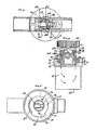
- soap dispenser 10 has a handle in the form of a conduit 12 connectable to the discharge end of a standard hose (e.g. garden hose), which provides a high pressure flow of water or fluid through the soap dispenser.
- a male threaded connector (not shown) on the hose is connected to an internal threaded connector 14 at the left end of conduit 12.
- the right end 16 of the conduit 12 is slipped into and locked by detentes on the intake end 28 of housing 18, which is detachably connected to a reservoir 20.
- Conduit 12 leads to the intake end of a main passageway 22 which extends through the housing 18 and a cylindrical valve 24, located in the valve cavity 26 portion of the housing.
- the passageway 22 will not extend through the housing and cylindrical valve 24 unless the cylindrical valve 24 is properly positioned.
- An O-ring 31, made of rubber or like material, is positioned at the end portion 16 of the conduit 12, and ensures against leakage of water between the intake tube 28 and the conduit 12.
- the discharge end 30 of the main passageway 23 is sized to snugly receive the extension of an intake tube (not shown) of a water wheel driven, rotary scrub brush.
- the discharge end 30 has external threads 33 for threading into internal threads of a connector (not shown).
- the housing has a ring-shaped flange 32 at its underside, for connection to a co ntainer 20, which together form a reservoir for a fluid or other material to be dispensed.
- the container 20 will be connected in such a manner as to ensure easy disconnection, as for refilling in the "off" position, and a leakproof fit when connected to the flange 32.
- the container has external threads 38 to receive internal threads 39 on the flange 32, at the bottom side of the housing 18.
- the container 20 is moulded to receive and hold an O-ring 19 of rubber or like material, and ensures against leakage of water between the container and flange 32 when the container 20 is fastened to the flange 32.
- a control knob 40 enables an operator of the soap dispenser 10 to directly effect the positioning of the cylindrical valve and thus control the main passageway 52, through the cylindrical valve (Fig. 1), and an auxiliary passageway 65 (Fig. 4).
- the control knob 40 is a circular disc-member which has conveniently placed on the top side markings which indicate "off", “soap” and “rinse” positions, as illustrated in Fig. 2.
- the control knob 40 is mounted in any conventional manner to the top side of the cylindrical valve 24.
- a standard screw 42 is used to secure the control knob 40 to the top end of the cylindrical valve.
- the control knob 40 is preferably large in diameter and extends past the edge of the housing 18, in order for the operator to get better leverage and grip for positioning the control knob 40 and cylindrical valve.
- a detente is provided in the upper part of the housing, below the control knob, to provide a slight resistance in the "off" position, for a mechanical indication of the "off" position.
- high pressure fluid such as water flows through the main passageway 22, which extends through the upstream portion of the housing 18, to an orifice 46 leading into the valve cavity 26.
- This cavity is cylindrical in shape, and contains the cylindrical valve 24.
- O-ring 50 preferably made of rubber or like material, seals tightly against and conforms to the outer side of the cylinrical valve in the valve cavity. The O-ring 50 helps to seal off intake water from the valve cavity 26 and the main passageway 22, when the cylindrical valve 24 is in the "off" position.
- the main passageway 22 extends diametrically through a central portion 52 of the cylindrical valve 24, so that the main passageway 22 allows flow therethrough when the control knob 40 is in either the "rinse” position (Figs. 1, 3) or the “soap” position (Figs. 6, 7).
- an upstream portion 54 of the main passageway 52, through the cylindrical valve has a large diameter; for example, of 3/8 inch, and a downstream portion 56, for example, of 1/4 inch. Accordingly, in Fig. 6, when the control knob is rotated 180° to the "rinse" position, the upstream portion 54 and downstream portion 56 are reserved.
- the cylindrical valve 24 has a smooth, cylindrical, wall surface 43, which is about the same size as, but slightly smaller than, the cylindrical-shaped valve cavity 26 and freely rotates within cylindrical valve cavity 26.
- a substantially watertight seal is formed between the O-ring 50 and the surface of the cylindrical shaped valve.
- the cylindrical valve 24 has two orifices 64 and 66 at the ends of two passageways 58 and 60 that extend from the upstream and downstream portions 54 and 56, respectively, of the main passageway 52 through the cylindrical valve 24.
- a disc-shaped valve member 63 extends from the cylindrical valve outwardly beyond the valve cavity 26 abutting with the flat side 41 of the housing.
- the valve member together with the cylindrical portion 49 of the cylindrical valve 24 are integrally moulded together as a unit, so that, when the control knob 40 is rotated, the valve member 63 rotates as well.
- Provided through the valve member 63 are two ports 74 and 76 which control passage of fluid through the auxiliary passageway 65 extending from the main passageway 52 (Fig. 3).
- the auxiliary passage 65 includes grooves 68 and 67 extending longitudinally along the wall surface 43 of the valve cavity 26, radial grooves 72 and 70 on the bottom side 41 of the housing and upstream and downstream passages 58 and 60.
- Rotation of the valve member 63 and the control knob 40 are limited by a circular stop wall 80 protruding from the bottom side of the housing 41.
- the circular stop wall 80 circumferentially surrounds the valve member 63 for, preferably, 90°.
- the valve member 63 is provided with an abutment 81 extending diametrically beyond the stop wall 80, and circumferentially around the valve member for, preferably, 90°. Together, the abutment and stop wall limit rotation of the valve member and cylindrical valve to only 180° rotations from the "soap" and "rinse" positions.
- valve member 63 In the "soap" position (Figs. 3, 4 and 6), the two ports 74 and 76 register with two reservoir grooves 70 and 72, respectively, of the auxiliary passageway 65 at the bottom of the housing 41.
- the top side of valve member 63 is forced up against the bottom side 41 of the housing 41 by a spring in the form of a wavy washer 61 located between the bottom surface of the control knob 40 and the top side of the housing 26.
- valve orifices 64 and 66 align with upstream housing groove 68 and a downstream housing groove 67, respectively (Fig. 4). These grooves are located between the valve cavity 26 and the cylindrical valve. Preferably, the grooves are moulded entirely within the wall surface 48 of the valve cavity 26. Each groove extends down to separate openings or reservoir grooves 70 and 72, respectively, in the surface of the bottom side 41 of the housing 18 (Fig. 5).
- the control knob is in the "soap" position, the upstream and downstream portions of main passageway 52 through the cylindrical valve 24 are remotely connected to the reservoir 20 by the auxiliary passageway 65.
- the present invention allows the opening or reservoir grooves 70 and 72 into the reservoir 20 to be closed off without the need for gaskets or O-rings to be attached to the grooves.
- grooves 68 and 67 are placed down the surface of the valve cavity to allow the grooves 70 and 72 to the reservoir 20 to be positioned at the minimum radial distance from the centre of rotation of the cylindrical valve and closely adjacent the outer edge of the valve cavity.
- O-ring 47 is positioned in a groove in the cylindrical valve between the top end of the cylindrical valve and the knob 40.
- pressure in the main passage will tend to lift the knob and cylindrical valve and enhance the seal between the upper surface of disc 63 and the bottom surface 41. In this way, the seal between the openings or grooves 70 and 72 are enhanced.
- the positionng of the O-ring 47 between the knob and cylindrical valve has a significant advantage over placing the O-ring in a groove at the top side of the housing.
- the control knob 40 would have difficulty sliding against the O-ring when the O-ring is under pressure.
- the O-ring is placed in a groove at the top side of the cylindrical valve so that the control knob, the cylindrical valve and the O-ring rotate together, even under pressure.
- the control knob When the control knob is turned to the "soap" position, the high pressure in the upstream portion 54 of the cylindrical valve 52 and low pressure at the downstream portion 56 are effective to shunt a stream of water through the auxiliary passageway 65.
- the diverted water leaves the main passageway 22 at an upstream high pressure location and re-enters the main passageway 23 at a downstream low pressure location.
- the diverted fluid flows in the auxiliary passage 65 through passage 58, port 64, housing groove 68, reservoir groove 72 and through port 76 to the reservoir 20 in the auxiliary passage 65 through port 74, reservoir groove 70, housing groove 67, port 66, passageway 60 and into the downstream portion 56 of the cylindrical valve 24.
- the soap dispenser may be used with or without soap. If depletion of the reservoir occurs, the reservoir can be refilled with soap by turning the control knob 40 to the "off" position, disconnecting the reservoir from the housing, refilling it with soap, and reconnecting it back into the housing.
- the invention is also expected to be useful with other materials such as waxes detergents or insecticides and the like.
- the housing including its cavity, passages, grooves, control knob detentes assembly, detentes and the cylindrical valve, including its valve member, passages, ports, splines and O-ring grooves, control knob including its spline, and container are all individually injection moulded as a unit to form individual, easily assembled, plastic parts, as described.
- Assembly is achieved by placing O-rings 50 and 47 in their respective grooves in the housing and cylindrical valve 24, by inserting the cylindrical valve 24 with O-ring 47 through the valve cavity from the bottom side 41, until the valve member surface 63 abuts the bottom side 41, by placing the wavy spring washer 61 around the cylindrical valve 24 on the top of the housing 18, by inserting the control knob 40 on the top end of the cylindrical valve 74, and wavy spring washer 61, by theading the screws through the control knob 40 into the upper end of the cylindrical valve 24, and by connecting the container 20 with O-ring 19 into the bottom side of the housing 18.
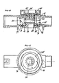
- Figs. 10 and 11 depict an alternative embodiment of the invention. Identical reference numerals indicate identical elements disclosed in Figs. 1-9. New reference numerals are used to indicate additional components.
- this embodiment invention also has a cylindricl valve 24 ⁇ insertable from the bottom side into the valve cavity 26 for mounting and rotation in the valve cavity.
- the cylindrical valve has a valve member of disc 63 ⁇ extending outwardly beyond the valve cavity into closely spaced opposed relation with the housing bottom side at 110.
- the exposed control knob 40 is again connected to the cylindrical valve at the top side of the housing for manually rotating the cylindrical valve and for securing a cylindrical valve, in and relative to the housing, so that the substantially opposed relation between the housing bottom side and the valve member is maintained.
- the auxiliary passageway extends from an upstream position in the main flow passage, through the reservoir, to the main flow passage at a position which is downstream from the upstream position.
- the first rotational position of the central knob causes the cylindrical valve to block the flow of fluid through the main passageway of the housing
- a second rotation position of the control knob and cylindrical valve provides communication of the fluid through the main passage of both the housing and the cylindrical valve, and communication of fluid through the auxiliary passageway and reservoir between the upstream and downstream positions
- a third rotation position of the control knob and cylindrical valve provide fluid communication through the main passageway of both the housing and the cylindrical valve and an obstruction by the valve member of the flow fluid through the auxiliary passageway.
- the auxiliary passageway includes an upstream passage 95 which extends from the main passage to a position between the bottom side of the housing and the valve member, downstream passage 74 which is alignable with passage 95 and passes through the valve member 63 ⁇ , downstream passage 96 which passes from the main passage to a position between the housing bottom side and valve member 63 ⁇ and a downstream passage 76, alignable with passage 96 through valve member 63 ⁇ .
- upstream passages 95 and 74 extend from the upstream side of the main passage to the reservoir whereas the downstream passages 96 and 76 extend from a position in the main passage which is downstream with respect to passages 95 and 74.
- the bottom side of the housing 41 may be equipped with a groove, essentially concentric about the valve cavity 26, with an O-ring 100 placed in the groove to provide additional seal between the cylindrical valve 24 ⁇ and the bottom side of the housing 41.
Landscapes
- Health & Medical Sciences (AREA)
- Life Sciences & Earth Sciences (AREA)
- Engineering & Computer Science (AREA)
- Hydrology & Water Resources (AREA)
- Public Health (AREA)
- Water Supply & Treatment (AREA)
- Containers And Packaging Bodies Having A Special Means To Remove Contents (AREA)
- Devices For Dispensing Beverages (AREA)
Claims (10)
- Fluidausgeber (10) für eine Quelle eines unter hohem Druck stehenden Fluids und ein weiteres Fluid, wobei der Ausgeber aufweist:
ein Gehäuse (18) mit einer ersten Seite und einer zweiten Seite (41), wobei die zweite Seite (41) ein Mittel (32) zum Anschließen eines Behälters (20) besitzt, der ein Fluidreservoir für das genannte zweite Fluid bildet; eine durch das Gehäuse (18) von der ersten Seite zu der zweiten Seite geformte Ventilkammer (26); ein in der Ventilkammer (26) drehbar eingesetztes zylindrisches Ventil (24); einen im wesentlichen quer zu der Ventilkammer durch das Gehäuse (18) und das Ventil (24) geformten Hauptdurchlaß (22, 52); ein Mittel (12) zum Anschließen eines stromauf gelegenen Abschnittes des Hauptdurchlasses (22, 52) an eine unter hohem Druck stehende Fluidquelle, einen an der ersten Seite des Gehäuses freiliegenden Schaltknopf (40), der mit dem zylindrischen Ventil verbunden ist, um das Ventil bezüglich des Gehäuses an der ersten Seite in Lage zu halten und um das zylindrische Ventil zu verdrehen; einen O-Ring (47), um eine Fluiddichtung zwischen dem Gehäuse und dem zylindrischen Ventil in Richtung der ersten Gehäuseseite bezüglich des Hauptdurchlasses zu bilden; und einen Hilfsdurchlaß (65), der sich von einer stromauf gelegenen Stelle in dem Hauptdurchlaß (22, 52) des Flusses zu dem Reservoir (20) und zurück zu einer bezüglich der stromauf gelegenen Stelle stromabwärts liegenden Stelle in dem Hauptdurchlaß (22, 52) erstreckt, gekennzeichnet durch ein mit dem zylindrischen Ventil (24) starres Ventilglied (63 oder 63') und dadurch, daß das zylindrische Ventil (24) von der zweiten Seite des Gehäuses (18) in die Ventilkammer (26) einsetzbar ist, wobei sich das Ventilglied (63, 63') von dem zylindrischen Ventil (24) nach außen zu einer der zweiten Seite des Gehäuses (18) benachbarten und dieser gegenüberliegenden Stelle erstreckt, um das Ventil (24) bezüglich der zweiten Seite des Gehäuses (18) in Lage zu halten, sodaß eine erste Verdrehlage des Schaltknopfes (40) dazu führt, daß das Ventil (24) den Fluß des unter hohem Druck stehenden Fluids durch den Hauptdurchlaß (22, 52) unterbricht, eine zweite Verdrehlage des Schaltknopfes (40) dazu führt, daß das Ventil (24) einen Hauptfluß von unter hohem Druck stehenden Fluid durch den Hauptdurchlaß (22, 52) und einen Sekundärfluß von unter hohem Druck stehenden Fluid längs des Hilfsdurchlasses (65) von dem Hauptdurchlaß (22, 52) zu dem Reservoir (20) und zurück zu dem Hauptdurchlaß (22, 52) ermöglicht, um hiedurch das zweite Fluid in das unter hohem Druck stehende Fluid in dem Hauptdurchlaß auszugeben und eine dritte Verdrehlage des Schaltknopfes (40) dazu führt, daß das zylindrische Ventil (24) einen Fluß von unter hohem Druck stehenden Fluid durch durch den Hauptdurchlaß (22, 52) des Gehäuses ermöglicht, während es jeglichen Fluß des Fluids durch den Hilfsdurchlaß (65) unterbricht. - Fluidausgeber nach Anspruch 1, dadurch gekennzeichnet, daß der Durchlaß (65) einen ersten stromauf gelegenen Durchlaß und einen ersten stromab gelegenen Durchlaß besitzt, welche Durchlässe sich von dem Hauptdurchlaß (22, 52) zu dem Ventilglied (63, 63') an Stellen zwischen dem Ventilglied (63, 63') und der zweiten Seite des Gehäuses (18) erstrecken und daß er in dem Ventilglied (63, 63') einen zweiten stromauf gelegenen Durchlaß und einen zweiten stromab gelegenen Durchlaß besitzt, welche Durchlässe mit dem ersten stromauf gelegenen Durchlaß bzw. mit dem ersten stromab gelegenen Durchlaß ausrichtbar sind.
- Fluidausgeber nach Anspruch 1 oder 2, gekennzeichnet durch einen O-Ring (50) zwischen dem Gehäuse (18) und dem zylindrischen Ventil (24), der an der stromauf gelegenen Seite des zylindrischen Ventils (24) um den Hauptdurchlaß (22, 52) verläuft.
- Fluidausgeber nach irgendeinem der Ansprüche 1 bis 3, dadurch gekennzeichnet, daß das Ventilglied (63, 63') scheibenförmig ist.
- Fluidausgeber nach irgendeinem der vorgehenden Ansprüche, gekennzeichnet durch eine zusätzliche Rille in der zweiten Seite des Gehäuses (18) um die Ventilkammer (26) herum, und durch einen O-Ring (100), der in der zusätzlichen Rille angeordnet ist, um zwischen der zweiten Seite des Gehäuses (18) und dem Ventilglied (63, 63') eine Fluiddichtung zu bilden.
- Fluidausgeber nach Anspruch 1, gekennzeichnet durch: getrennte, stromauf und stromab gelegene Gehäuserillen (68, 67) in der Ventilkammer, wobei sich jede der Rillen zu einer verschiedenen Stelle an der zweiten Seite des Gehäuses (18) erstreckt; einen stromauf gelegenen Ventildurchlaß (58), der sich von der stromauf gelegenen Stelle des Hauptdurchlasses (22, 52) durch das zylindrische Ventil (24) zu der stromauf gelegenen Gehäuserille erstreckt; einen stromab gelegenen Ventildurchlaß (60), der sich von der stromab gelegenen Stelle des Hauptdurchlasses durch das zylindrische Ventil zu der stromab gelegenen Gehäuserille erstreckt; wobei die zweite Verdrehlage des Schaltknopfes (40) ein Kommunizieren von Fluid durch den Hauptdurchlaß (22, 52) des Gehäuses (18) ermöglicht, sowie das Kommunizieren von Fluid durch den stromauf gelegenen Ventildurchlaß (58) und die stromauf gelegene Rille, durch das Reservoir (20) und durch die stromab gelegene Rille und den stromab gelegenen Ventildurchlaß (60) und zurück zu dem Hauptdurchlaß (22, 52); und wobei die dritte Verdrehstellung des Schaltknopfes (40) eine Fluidkommunikation durch den Hauptdurchlaß (22, 52) des Gehäuses (18) ermöglicht, während sie das Ventilglied in eine Lage zum Verschließen der Öffnung zumindest einer der Rillen zu dem Reservoir (20) hin bringt.
- Fluidausgeber nach Anspruch 1, dadurch gekennzeichnet, daß sich der Hilfsdurchlaß (65) von einer stromauf gelegenen Stelle in dem Hauptdurchlaß (22, 52) des Flusses durch einen in dem Gehäuse (18) ausgebildeten, stromauf gelegenen Durchlaß (95) erstreckt, dann durch einen in dem Ventilglied (63') ausgebildeten, stromauf gelegenen Durchlaß (74), und in das Reservoir (20) und durch einen in dem Ventilglied (63, 63') ausgebildeten, stromab gelegenen Durchlaß (76), sodann durch einen in dem Gehäuse (18) ausgebildeten, stromab gelegenen Durchlaß (96) und zu einer stromauf gelegenen Stelle in dem Hauptdurchlaß (22, 52) des Flusses, wobei die stromauf und stromab gelegenen Durchlässe (74, 76) in dem Ventilglied (63') mit den stromauf und stromab gelegenen Durchlässen (95, 96) in dem Gehäuse (18) ausgerichtet sind, wenn sich der Schaltknopf (40) in der zweiten Lage befindet.
- Fluidausgeber nach Anspruch 1, dadurch gekennzeichnet, daß sich der Hilfsdurchlaß (65) von einer stromauf gelegenen Stelle in dem Hauptdurchlaß des Flusses durch das zylindrische Ventil (24), zwischen dem zylindrischen Ventil (24) und dem Gehäuse (18), zu dem Reservoir (20) erstreckt, sodann von dem Gehäuse (20) zwischen dem zylindrischen Ventil (24) und dem Gehäuse (18), und durch das zylindrische Ventil (24) zurück zu der stromab gelegenen Stelle des Hauptdurchlasses (22, 52).
- Fluidausgeber nach Anspruch 1, dadurch gekennzeichnet, daß der Hilfsdurchlaß (65) eine Rille zwischen dem Gehäuse (18) und dem zylindrischen Ventil (24) aufweist.
- Fluidausgeber nach Anspruch 1, dadurch gekennzeichnet, daß der Hilfsdurchlaß voneinander beabstandete Rillen, eine erste und eine zweite, aufweist, die sich zu dem Reservoir (20) erstrecken, wobei die erste und die zweite der beabstandeten Rillen zwischen dem Gehäuse (18) und dem zylindrischen Ventil (24) ausgebildet sind.
Priority Applications (1)
| Application Number | Priority Date | Filing Date | Title |
|---|---|---|---|
| AT87307214T ATE67543T1 (de) | 1986-08-27 | 1987-08-14 | Fluessigkeitsspender. |
Applications Claiming Priority (4)
| Application Number | Priority Date | Filing Date | Title |
|---|---|---|---|
| US90083886A | 1986-08-27 | 1986-08-27 | |
| US900838 | 1986-08-27 | ||
| US07/077,754 US4785850A (en) | 1986-11-07 | 1987-07-27 | Cylindrical valve soap dispenser |
| US77754 | 1987-07-27 |
Publications (2)
| Publication Number | Publication Date |
|---|---|
| EP0261784A1 EP0261784A1 (de) | 1988-03-30 |
| EP0261784B1 true EP0261784B1 (de) | 1991-09-18 |
Family
ID=26759643
Family Applications (1)
| Application Number | Title | Priority Date | Filing Date |
|---|---|---|---|
| EP87307214A Expired - Lifetime EP0261784B1 (de) | 1986-08-27 | 1987-08-14 | Flüssigkeitsspender |
Country Status (5)
| Country | Link |
|---|---|
| EP (1) | EP0261784B1 (de) |
| CA (1) | CA1308697C (de) |
| DE (1) | DE3773101D1 (de) |
| ES (1) | ES2026915T3 (de) |
| GR (1) | GR3003316T3 (de) |
Families Citing this family (1)
| Publication number | Priority date | Publication date | Assignee | Title |
|---|---|---|---|---|
| IT1227597B (it) * | 1988-12-14 | 1991-04-22 | Claber Spa | Miscelatore di liquidi |
Citations (1)
| Publication number | Priority date | Publication date | Assignee | Title |
|---|---|---|---|---|
| US4369921A (en) * | 1980-12-12 | 1983-01-25 | Acme Burgess, Inc. | Hose-end sprayer |
Family Cites Families (4)
| Publication number | Priority date | Publication date | Assignee | Title |
|---|---|---|---|---|
| US3447753A (en) * | 1967-01-27 | 1969-06-03 | Jet X Corp | Spray washer with detergent feed |
| US3770205A (en) * | 1972-08-24 | 1973-11-06 | Jet X Corp | Sprayer with detergent or chemical additive feed |
| US4281796A (en) * | 1979-03-15 | 1981-08-04 | Fugent Elmer G | Bathroom mixing device |
| DE3138876A1 (de) * | 1981-09-30 | 1983-04-14 | Josef 7965 Ostrach Walter | Dusche, insbesondere handbrause |
-
1987
- 1987-08-14 DE DE8787307214T patent/DE3773101D1/de not_active Expired - Fee Related
- 1987-08-14 EP EP87307214A patent/EP0261784B1/de not_active Expired - Lifetime
- 1987-08-14 ES ES87307214T patent/ES2026915T3/es not_active Expired - Lifetime
- 1987-08-26 CA CA000545445A patent/CA1308697C/en not_active Expired - Lifetime
-
1991
- 1991-12-11 GR GR91401940T patent/GR3003316T3/el unknown
Patent Citations (1)
| Publication number | Priority date | Publication date | Assignee | Title |
|---|---|---|---|---|
| US4369921A (en) * | 1980-12-12 | 1983-01-25 | Acme Burgess, Inc. | Hose-end sprayer |
Also Published As
| Publication number | Publication date |
|---|---|
| GR3003316T3 (en) | 1993-02-17 |
| CA1308697C (en) | 1992-10-13 |
| EP0261784A1 (de) | 1988-03-30 |
| ES2026915T3 (es) | 1992-05-16 |
| DE3773101D1 (de) | 1991-10-24 |
Similar Documents
| Publication | Publication Date | Title |
|---|---|---|
| US4785850A (en) | Cylindrical valve soap dispenser | |
| US5299608A (en) | Sealed coupling for a fluid container | |
| US10328398B2 (en) | Multiple function dispenser | |
| ES2231427T3 (es) | Pulverizador del tipo de aspiracion para montar en el extremo de una manguera. | |
| KR101059671B1 (ko) | 개선된 다기능 분배기 | |
| AU575785B2 (en) | Variable dilution ratio hose-end sprayer | |
| ES2252824T3 (es) | Dispositivo de pulverizacion mejorado. | |
| US5653261A (en) | Selector valve | |
| WO2006115865A2 (en) | Liquid sprayer assembly | |
| US4632362A (en) | Tap | |
| US10465818B2 (en) | Faucet connector | |
| JP2837911B2 (ja) | 混合弁ユニット | |
| US4607793A (en) | Shower head which uniformly dispenses liquid additives | |
| CN100335835C (zh) | 流量限制器 | |
| US20040140372A1 (en) | Single longitudinal valve ready to use hose end sprayer | |
| CA1257581A (en) | Admixer for delivering soluble additives | |
| US20050189436A1 (en) | Longitudinal valve ready to use hose end sprayer | |
| US5377718A (en) | Selecting and dispensing valve | |
| US6050286A (en) | Sequencing valve | |
| US5123449A (en) | Selector valve | |
| US4644970A (en) | Mixing faucet | |
| EP0261784A1 (de) | Flüssigkeitsspender | |
| US6371386B1 (en) | Soap dispenser | |
| CN113623425A (zh) | 一种分水阀和淋浴器 | |
| EP3438516A1 (de) | Wasserhahnverbinder |
Legal Events
| Date | Code | Title | Description |
|---|---|---|---|
| PUAI | Public reference made under article 153(3) epc to a published international application that has entered the european phase |
Free format text: ORIGINAL CODE: 0009012 |
|
| AK | Designated contracting states |
Kind code of ref document: A1 Designated state(s): AT BE CH DE ES FR GB GR IT LI LU NL SE |
|
| 17P | Request for examination filed |
Effective date: 19880922 |
|
| 17Q | First examination report despatched |
Effective date: 19890220 |
|
| RAP1 | Party data changed (applicant data changed or rights of an application transferred) |
Owner name: SWIRLON INDUSTRIES, INC. |
|
| GRAA | (expected) grant |
Free format text: ORIGINAL CODE: 0009210 |
|
| AK | Designated contracting states |
Kind code of ref document: B1 Designated state(s): AT BE CH DE ES FR GB GR IT LI LU NL SE |
|
| PG25 | Lapsed in a contracting state [announced via postgrant information from national office to epo] |
Ref country code: GR Free format text: LAPSE BECAUSE OF FAILURE TO SUBMIT A TRANSLATION OF THE DESCRIPTION OR TO PAY THE FEE WITHIN THE PRESCRIBED TIME-LIMIT Effective date: 19910918 |
|
| REF | Corresponds to: |
Ref document number: 67543 Country of ref document: AT Date of ref document: 19911015 Kind code of ref document: T |
|
| REF | Corresponds to: |
Ref document number: 3773101 Country of ref document: DE Date of ref document: 19911024 |
|
| ITF | It: translation for a ep patent filed | ||
| ET | Fr: translation filed | ||
| REG | Reference to a national code |
Ref country code: ES Ref legal event code: FG2A Ref document number: 2026915 Country of ref document: ES Kind code of ref document: T3 |
|
| PLBE | No opposition filed within time limit |
Free format text: ORIGINAL CODE: 0009261 |
|
| STAA | Information on the status of an ep patent application or granted ep patent |
Free format text: STATUS: NO OPPOSITION FILED WITHIN TIME LIMIT |
|
| PGFP | Annual fee paid to national office [announced via postgrant information from national office to epo] |
Ref country code: GB Payment date: 19920731 Year of fee payment: 6 |
|
| PG25 | Lapsed in a contracting state [announced via postgrant information from national office to epo] |
Ref country code: AT Effective date: 19920814 |
|
| PG25 | Lapsed in a contracting state [announced via postgrant information from national office to epo] |
Ref country code: SE Effective date: 19920815 |
|
| PG25 | Lapsed in a contracting state [announced via postgrant information from national office to epo] |
Ref country code: ES Free format text: LAPSE BECAUSE OF THE APPLICANT RENOUNCES Effective date: 19920817 |
|
| PG25 | Lapsed in a contracting state [announced via postgrant information from national office to epo] |
Ref country code: LU Free format text: LAPSE BECAUSE OF NON-PAYMENT OF DUE FEES Effective date: 19920831 Ref country code: LI Effective date: 19920831 Ref country code: CH Effective date: 19920831 Ref country code: BE Effective date: 19920831 |
|
| PGFP | Annual fee paid to national office [announced via postgrant information from national office to epo] |
Ref country code: NL Payment date: 19920831 Year of fee payment: 6 |
|
| 26N | No opposition filed | ||
| REG | Reference to a national code |
Ref country code: GR Ref legal event code: FG4A Free format text: 3003316 |
|
| BERE | Be: lapsed |
Owner name: SWIRLON INDUSTRIES INC. Effective date: 19920831 |
|
| PG25 | Lapsed in a contracting state [announced via postgrant information from national office to epo] |
Ref country code: NL Effective date: 19930301 |
|
| NLV4 | Nl: lapsed or anulled due to non-payment of the annual fee | ||
| PG25 | Lapsed in a contracting state [announced via postgrant information from national office to epo] |
Ref country code: FR Effective date: 19930430 |
|
| REG | Reference to a national code |
Ref country code: CH Ref legal event code: PL |
|
| PG25 | Lapsed in a contracting state [announced via postgrant information from national office to epo] |
Ref country code: DE Effective date: 19930501 |
|
| REG | Reference to a national code |
Ref country code: FR Ref legal event code: ST |
|
| PG25 | Lapsed in a contracting state [announced via postgrant information from national office to epo] |
Ref country code: GB Effective date: 19930814 |
|
| GBPC | Gb: european patent ceased through non-payment of renewal fee |
Effective date: 19930814 |
|
| REG | Reference to a national code |
Ref country code: GR Ref legal event code: MM2A Free format text: 3003316 |
|
| EUG | Se: european patent has lapsed |
Ref document number: 87307214.4 Effective date: 19930307 |
|
| REG | Reference to a national code |
Ref country code: ES Ref legal event code: FD2A Effective date: 19991007 |
|
| PG25 | Lapsed in a contracting state [announced via postgrant information from national office to epo] |
Ref country code: IT Free format text: LAPSE BECAUSE OF NON-PAYMENT OF DUE FEES;WARNING: LAPSES OF ITALIAN PATENTS WITH EFFECTIVE DATE BEFORE 2007 MAY HAVE OCCURRED AT ANY TIME BEFORE 2007. THE CORRECT EFFECTIVE DATE MAY BE DIFFERENT FROM THE ONE RECORDED. Effective date: 20050814 |