EP0261796A1 - Conducteur contourné longitudinalement destiné à des dispositifs électriques à induction - Google Patents
Conducteur contourné longitudinalement destiné à des dispositifs électriques à induction Download PDFInfo
- Publication number
- EP0261796A1 EP0261796A1 EP87307425A EP87307425A EP0261796A1 EP 0261796 A1 EP0261796 A1 EP 0261796A1 EP 87307425 A EP87307425 A EP 87307425A EP 87307425 A EP87307425 A EP 87307425A EP 0261796 A1 EP0261796 A1 EP 0261796A1
- Authority
- EP
- European Patent Office
- Prior art keywords
- conductor
- coil
- contoured
- induction device
- current carrying
- Prior art date
- Legal status (The legal status is an assumption and is not a legal conclusion. Google has not performed a legal analysis and makes no representation as to the accuracy of the status listed.)
- Withdrawn
Links
- 239000004020 conductor Substances 0.000 title claims abstract description 36
- 230000001939 inductive effect Effects 0.000 title description 4
- 238000005520 cutting process Methods 0.000 claims description 2
- 230000006698 induction Effects 0.000 claims 5
- 239000000463 material Substances 0.000 abstract description 10
- 238000004804 winding Methods 0.000 abstract description 2
- RYGMFSIKBFXOCR-UHFFFAOYSA-N Copper Chemical compound [Cu] RYGMFSIKBFXOCR-UHFFFAOYSA-N 0.000 description 4
- 229910052802 copper Inorganic materials 0.000 description 4
- 239000010949 copper Substances 0.000 description 4
- 238000000034 method Methods 0.000 description 4
- 238000010276 construction Methods 0.000 description 3
- 239000011810 insulating material Substances 0.000 description 2
- 238000003754 machining Methods 0.000 description 2
- 238000004519 manufacturing process Methods 0.000 description 2
- 230000000087 stabilizing effect Effects 0.000 description 2
- 230000003247 decreasing effect Effects 0.000 description 1
- 230000005298 paramagnetic effect Effects 0.000 description 1
- 239000007787 solid Substances 0.000 description 1
- 230000006641 stabilisation Effects 0.000 description 1
- 238000011105 stabilization Methods 0.000 description 1
- 238000003860 storage Methods 0.000 description 1
- 239000002966 varnish Substances 0.000 description 1
Images


Classifications
-
- H—ELECTRICITY
- H01—ELECTRIC ELEMENTS
- H01F—MAGNETS; INDUCTANCES; TRANSFORMERS; SELECTION OF MATERIALS FOR THEIR MAGNETIC PROPERTIES
- H01F27/00—Details of transformers or inductances, in general
- H01F27/28—Coils; Windings; Conductive connections
- H01F27/2823—Wires
Definitions
- the present invention is related to inductive electrical devices in which there is a varying current density, and more particular to a longitudinally contoured conductor for such devices which minimizes the quantity of required conductor material.
- Inductive electrical devices are well known and widely used in electrical systems as energy transfer or storage elements and include, for example, variable transformers and certain types of choke coils and reactors in which a coiled conductor induces a voltage in itself or another coil, frequently in association with a paramagnetic flux-carrying material.
- the conductors of such devices are typically formed of round, rectangular, or square conductors with the conductor in any such device having a uniform cross section substantially throughout its length.
- the current handling requirements in a conductur in such devices may change with respect to the position in the conductor; however, by using constant cross-section conductors, the coils are designed to withstand the maximum currents throughout the coil when, in actuality, only certain portions of the coil carry the maximum currents.
- This conventional configuration wastes conductor material and results in a device that is heavier and larger than need be for the current carried.
- the present invention overcomes the above limitations of conventional devices by providing a coil for an inductive device that is longitudinally contoured so that is has maximum cross sectional area in those sections where maximum current is carried and lesser cross sectional areas, proportional to the current carrued, in other sections of the coil.
- a suggested method of producing such a coil also results in a greatly simplified manufacturing process.
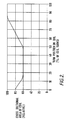
- Figure 1 is a graph, for a typical variable transformer, of the maximum current handling requirement of the transformer coil versus the turn position on the coil. Curves are shown for both constant current load operation and constant impedance load operation. For constant current load operation, it is seen that, at the beginning of the coil, the current is at its maximum, drops to about one-half maximum, and then rises to and remains at maximum along the last 20 percent of the coil. For constant impedance load operation, the current is at a low level along the first half of the coil and then rises along the rest of the coil.
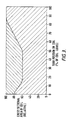
- Figure 2 shows how a coil might be contoured, in accordance with the present invention, for the transformer requirements shown on Figure 1.
- the contouring indicated satisfies the requirements for both constant current and constant impedance load conditions.
- the cross sectional area is relatively large to handle constant current load conditions, drops to a lower level when the current is relatively low under either load condition, and then rises to its maximum toward the end of the coil to handle the maximum current under constant impedance load operation.
- Figure 3 is Figure 2 shaded to show coil material saved in a coil i n accordance with the present invention over conventional construction.
- the lower, shaded area shows the relative amount of coil material used in a coil contoured in accordance with the invention, and the upper, shaded area shows the relative amount of coil material saved over a standard coil. It follows that the entire shading shows the relative amount of material used on a standard coil. For the design under construction, there is a savings of about 20 percent in coil material.
- Figure 4 shows a coil constructed in accordance with the present invention and includes a conductor 10 on the surface of a tube of insulating material 11. Beginning at the left end of the coil 10, section “A” begins with relatively wide coil turns decreasing to the minimum width section "B". the width of the coil turns increases through section “C” to the maximum width coil turns in section “D” at the right end of the coil 10. The contouring is substantially shown on Figure 2.
- the coil may be cut from a solid tube of electrical grade copper. Prior to cutting the contoured turns, the coil is stabilized by threading the inside diameter of the copper tube, screwing it onto the outside diameter of a threaded tube of the insulating material 11, and bonding these two pieces together. The bonding may be achieved by vacuum impregnating the assembly with transformer varnish, thus thoroughly stabilizing the future coil. After this stabilization process has been completed, the coil is cut from the copper tube by a numerically controlled machine. Numerically controlled machining can easily vary the pitch of the cuts made through the copper tube, thus achieving the desired coil conductor width variances through simple numerically controlled programming.
- the completed coil, stabilized on the insulating tube, requires very little finish machining.
- the procedure also allows an accurate brush guide to be easily machined into the coil, if the coil is of the type requiring a contact brush.
- another advantage to the present invention is in eliminating complicated manufacturing processes and costly tooling. Specifically, it eliminates the need for winding/coiling rectangular or square wire and the complicated process of accurately positioning and stabilizing turns of the transformer's coil.
Landscapes
- Engineering & Computer Science (AREA)
- Power Engineering (AREA)
- Coils Of Transformers For General Uses (AREA)
Applications Claiming Priority (2)
| Application Number | Priority Date | Filing Date | Title |
|---|---|---|---|
| US90011886A | 1986-08-25 | 1986-08-25 | |
| US900118 | 1986-08-25 |
Publications (1)
| Publication Number | Publication Date |
|---|---|
| EP0261796A1 true EP0261796A1 (fr) | 1988-03-30 |
Family
ID=25411997
Family Applications (1)
| Application Number | Title | Priority Date | Filing Date |
|---|---|---|---|
| EP87307425A Withdrawn EP0261796A1 (fr) | 1986-08-25 | 1987-08-21 | Conducteur contourné longitudinalement destiné à des dispositifs électriques à induction |
Country Status (2)
| Country | Link |
|---|---|
| EP (1) | EP0261796A1 (fr) |
| JP (1) | JPS6356904A (fr) |
Cited By (4)
| Publication number | Priority date | Publication date | Assignee | Title |
|---|---|---|---|---|
| WO1998024098A1 (fr) * | 1996-11-27 | 1998-06-04 | British Nuclear Fuels Plc | Ameliorations relatives a des bobines |
| EP1265260A1 (fr) * | 2001-06-06 | 2002-12-11 | Nexans | Fil métallique |
| DE10120236C1 (de) * | 2001-04-19 | 2003-01-30 | Siemens Ag | Elektrische Wicklungsanordnung |
| FR2854982A1 (fr) * | 2003-05-16 | 2004-11-19 | Jean Paul Scherrer | Enroulement pour transformateur et son procede de fabrication |
Families Citing this family (1)
| Publication number | Priority date | Publication date | Assignee | Title |
|---|---|---|---|---|
| US5791968A (en) * | 1992-10-21 | 1998-08-11 | Kawasaki Jukogyo Kabushiki Kaisha | Grinding method and grinding system for steels |
Citations (7)
| Publication number | Priority date | Publication date | Assignee | Title |
|---|---|---|---|---|
| DE295188C (fr) * | ||||
| DE414841C (de) * | 1921-11-20 | 1925-06-13 | Edmund Schroeder | Transformator fuer elektrische Schweiss- und Erwaermungsmaschinen |
| DE950871C (de) * | 1953-09-18 | 1956-10-18 | Standard Elek K Ag | Aus parallel geschalteten Scheibenspulen aufgebaute Hochstromwicklung fuer Transformatoren |
| FR1209196A (fr) * | 1958-05-31 | 1960-02-29 | Centre Nat Rech Scient | Nouvelles bobines sans fer pour la production de champs magnétiques permanents ou transitoires |
| FR1308052A (fr) * | 1961-09-22 | 1962-11-03 | Comp Generale Electricite | Enroulement pour transformateur |
| US3731243A (en) * | 1971-12-08 | 1973-05-01 | A Davis | Inductive winding |
| US4135173A (en) * | 1976-05-14 | 1979-01-16 | General Electric Company | Low volume sheet-wound transformer coils with uniform temperature distribution |
Family Cites Families (1)
| Publication number | Priority date | Publication date | Assignee | Title |
|---|---|---|---|---|
| JPS6059509B2 (ja) * | 1981-03-02 | 1985-12-25 | 川崎製鉄株式会社 | 高温炉炉内測定用ゾンデ |
-
1987
- 1987-08-20 JP JP20529287A patent/JPS6356904A/ja active Pending
- 1987-08-21 EP EP87307425A patent/EP0261796A1/fr not_active Withdrawn
Patent Citations (7)
| Publication number | Priority date | Publication date | Assignee | Title |
|---|---|---|---|---|
| DE295188C (fr) * | ||||
| DE414841C (de) * | 1921-11-20 | 1925-06-13 | Edmund Schroeder | Transformator fuer elektrische Schweiss- und Erwaermungsmaschinen |
| DE950871C (de) * | 1953-09-18 | 1956-10-18 | Standard Elek K Ag | Aus parallel geschalteten Scheibenspulen aufgebaute Hochstromwicklung fuer Transformatoren |
| FR1209196A (fr) * | 1958-05-31 | 1960-02-29 | Centre Nat Rech Scient | Nouvelles bobines sans fer pour la production de champs magnétiques permanents ou transitoires |
| FR1308052A (fr) * | 1961-09-22 | 1962-11-03 | Comp Generale Electricite | Enroulement pour transformateur |
| US3731243A (en) * | 1971-12-08 | 1973-05-01 | A Davis | Inductive winding |
| US4135173A (en) * | 1976-05-14 | 1979-01-16 | General Electric Company | Low volume sheet-wound transformer coils with uniform temperature distribution |
Cited By (4)
| Publication number | Priority date | Publication date | Assignee | Title |
|---|---|---|---|---|
| WO1998024098A1 (fr) * | 1996-11-27 | 1998-06-04 | British Nuclear Fuels Plc | Ameliorations relatives a des bobines |
| DE10120236C1 (de) * | 2001-04-19 | 2003-01-30 | Siemens Ag | Elektrische Wicklungsanordnung |
| EP1265260A1 (fr) * | 2001-06-06 | 2002-12-11 | Nexans | Fil métallique |
| FR2854982A1 (fr) * | 2003-05-16 | 2004-11-19 | Jean Paul Scherrer | Enroulement pour transformateur et son procede de fabrication |
Also Published As
| Publication number | Publication date |
|---|---|
| JPS6356904A (ja) | 1988-03-11 |
Similar Documents
| Publication | Publication Date | Title |
|---|---|---|
| DE60033238T2 (de) | Kern-spulenanordnung für induktivität und verfahren zu ihrer herstellung | |
| US4061007A (en) | Electromagnetic dent remover with electromagnetic localized work coil | |
| US3988650A (en) | Aluminum-electrolytic capacitor having a low impedance and low inductance | |
| US4259654A (en) | Flux control in tape windings | |
| JPH0696941A (ja) | 部分ギャップ磁気コア装置 | |
| GB2257840A (en) | Distribution transformers. | |
| US6211498B1 (en) | Induction heating apparatus and transformer | |
| EP0261796A1 (fr) | Conducteur contourné longitudinalement destiné à des dispositifs électriques à induction | |
| US5032816A (en) | Longitudinally contoured conductor for inductive electrical devices | |
| DE2939147A1 (de) | Verschiebungs-umwandler | |
| US4894907A (en) | Method of making a longitudinally contoured conductor for inductive electrical devices | |
| DE19814896A1 (de) | Leistungsübertrager für hohe Ströme | |
| US4188599A (en) | Inductance coil for telecommunication system and method of making same | |
| US4127933A (en) | Method of making work coil for an electromagnetic dent remover | |
| US4868533A (en) | Transformer with a one-piece primary winding and housing | |
| DE10049817B4 (de) | Induktionsvorrichtung mit Dämpfungseinrichtung | |
| EP0180301A3 (en) | High efficiency autoregulating heater | |
| JPH0541324A (ja) | ソレノイドコイル | |
| DE2812757C2 (de) | Konstantstrom-Transformator für Gasentladungsröhren | |
| EP1048925A2 (fr) | Palpeur inductif pour machine outil thermique | |
| WO2026021785A1 (fr) | Transformateur toroïdal à inductance de fuite | |
| DE102008017314B4 (de) | Induktives Bauelement und elektronische Schaltung zur Ansteuerung einer Leuchte | |
| WO2020088954A1 (fr) | Circuit résonnant pour la transmission d'énergie électrique | |
| CA1305534C (fr) | Appareil de chauffage haute frequence | |
| GB1598729A (en) | Inductive voltage transformer |
Legal Events
| Date | Code | Title | Description |
|---|---|---|---|
| PUAI | Public reference made under article 153(3) epc to a published international application that has entered the european phase |
Free format text: ORIGINAL CODE: 0009012 |
|
| AK | Designated contracting states |
Kind code of ref document: A1 Designated state(s): DE FR GB IT |
|
| 17P | Request for examination filed |
Effective date: 19880928 |
|
| 17Q | First examination report despatched |
Effective date: 19910523 |
|
| STAA | Information on the status of an ep patent application or granted ep patent |
Free format text: STATUS: THE APPLICATION IS DEEMED TO BE WITHDRAWN |
|
| 18D | Application deemed to be withdrawn |
Effective date: 19911204 |
|
| RIN1 | Information on inventor provided before grant (corrected) |
Inventor name: LENZING, RICHARD STEVEN Inventor name: WATT, JULIAN ALEXANDER |