EP0261882A1 - Abgabevorrichtung einer Flüssigkeitsmenge aus einem Behälter - Google Patents
Abgabevorrichtung einer Flüssigkeitsmenge aus einem Behälter Download PDFInfo
- Publication number
- EP0261882A1 EP0261882A1 EP87308262A EP87308262A EP0261882A1 EP 0261882 A1 EP0261882 A1 EP 0261882A1 EP 87308262 A EP87308262 A EP 87308262A EP 87308262 A EP87308262 A EP 87308262A EP 0261882 A1 EP0261882 A1 EP 0261882A1
- Authority
- EP
- European Patent Office
- Prior art keywords
- control member
- seating
- liquid
- container
- transfer chamber
- Prior art date
- Legal status (The legal status is an assumption and is not a legal conclusion. Google has not performed a legal analysis and makes no representation as to the accuracy of the status listed.)
- Withdrawn
Links
Images


Classifications
-
- A—HUMAN NECESSITIES
- A47—FURNITURE; DOMESTIC ARTICLES OR APPLIANCES; COFFEE MILLS; SPICE MILLS; SUCTION CLEANERS IN GENERAL
- A47K—SANITARY EQUIPMENT; ACCESSORIES THEREFOR, e.g. TOILET ACCESSORIES
- A47K5/00—Holders or dispensers for soap, toothpaste or the like
- A47K5/06—Dispensers for soap
- A47K5/12—Dispensers for soap for liquid or pasty soap
-
- E—FIXED CONSTRUCTIONS
- E03—WATER SUPPLY; SEWERAGE
- E03D—WATER-CLOSETS OR URINALS WITH FLUSHING DEVICES; FLUSHING VALVES THEREFOR
- E03D9/00—Sanitary or other accessories for lavatories ; Devices for cleaning or disinfecting the toilet room or the toilet bowl; Devices for eliminating smells
- E03D9/02—Devices adding a disinfecting, deodorising, or cleaning agent to the water while flushing
- E03D9/03—Devices adding a disinfecting, deodorising, or cleaning agent to the water while flushing consisting of a separate container with an outlet through which the agent is introduced into the flushing water, e.g. by suction ; Devices for agents in direct contact with flushing water
- E03D9/033—Devices placed inside or dispensing into the cistern
- E03D9/037—Active dispensers, i.e. comprising a moving dosing element
-
- E—FIXED CONSTRUCTIONS
- E03—WATER SUPPLY; SEWERAGE
- E03D—WATER-CLOSETS OR URINALS WITH FLUSHING DEVICES; FLUSHING VALVES THEREFOR
- E03D9/00—Sanitary or other accessories for lavatories ; Devices for cleaning or disinfecting the toilet room or the toilet bowl; Devices for eliminating smells
- E03D9/02—Devices adding a disinfecting, deodorising, or cleaning agent to the water while flushing
- E03D2009/028—Devices adding a disinfecting, deodorising, or cleaning agent to the water while flushing using a liquid substance
Definitions
- This invention relates to a device for dispensing a quantity of liquid from a container, in particular, but not exclusively, the device is for delivering a small amount of a liquid disinfectant or cleaner into the water in a domestic toilet cistern.
- complex metering valve arrangements are arranged to dose metered amounts of a treatment substance into the water supply line.
- Normally such arrangements are found in institutional installations and are for very specific purposes not suitable for general use in domestic or like installations where critical control requiring plumbed in metering valves is not essential.
- Furthermore, such installed arrangements are very costly and could not be justified in a domestic situation where hygienic control is merely desirable.
- liquid may comprise a soap or detergent, water additive, essence, shampoo etc., and herein the term "liquid" is intended to include all such liquid substances or compositions.
- An object of this invention is to provide a device for use with a container holding a liquid, and the device is arranged to dispense a small quantity of the liquid from the container when supported in an inverted mode and to be sealed closed after a dispensing discharge of the liquid.
- a further object of this invention is to provide a dispensing device of simple construction which is adapted for mounting in the neck of a container for the liquid so that the treatment liquid can be dispensed from the container when located in the cistern or like reservoir of water in response to a change of water level.
- a device for dispensing a small quantity of liquid from a container comprising a tubular seating member and a control member, the seating memb er having a mounting flange at one end to mount the device in the mouth of the container with the seating member depending into the container to confine liquid within the container for controlled discharge through an inlet port defined by a valve seating at the other end of the seating member, the control member having a body received within the seating member and mounted for limited relative axial displacement between inner and outer positions, the control member further having a valve head connected to the body by a neck portion extending through the seating member so that the valve head engages the valve seating when the control member is in the outer position to close the inlet port to prevent discharge of liquid from the interior of the container, the inlet port leading to a transfer chamber defined between the seating member and the body of the control member into which treatment liquid is discharged when the control member is in the inner position in which the valve head is disengaged from the valve seating, the seating member having an outlet port axially spaced
- the liquid confined with a container may be dispensed as a small quantity dose according to the designed volume of the transfer chamber by a simple displacement of the control member in one sense whilst the transfer chamber is recharged on return movement of the control member that closes the outlet port from the transfer chamber.
- the body of the control member is preferably of tubular form providing a void chamber open for admission of air and/or water in use of the device.
- the displacement of the control member is caused by a change in water level in a cistern in which the container is suspended with the mouth of the container being arranged at a level in which the device is covered by the water when the cistern is full and the control member is in the inner position due to air and/or water pressure acting on the control member and, on a reduction of level of the water on operation of the flushing valve of the cistern, then the mouth of the container with the device is uncovered and the control member is displaced to the outer position to dispense the small quantity of treatment liquid from the transfer chamber through the outlet port into the cistern.
- the control member On refilling of the cistern, the control member is acted on by the air and/or water to return to the inner position whereby the transfer chamber is recharged ready for the next actuation on change of water level in the cistern.
- the tubular form of the control body with the void chamber permits air and/or water to be admitted or released. Therefrom on such relative change in water level with the control body being responsive to the floatation or pressure affects of air and/or water in the void chamber.
- the small quantity which is dispensed by the invented device from the container is a single dose for each filling of the cistern, a nd the dispensing of each dose is automatic in response to the change in water level.
- the control member serves to respond to the change in water level in this preferred application, but the control member could be displaced by some other means in other applications.
- valve head is larger than the inlet port opening through the seating member so that the control member is retained and assembled to the seating member by the neck which extends through the inlet port opening with the valve head preventing the control member from being displaced through the inlet port opening.
- valve head of the control member is of frusto-conical form to engage the inlet port of which the seating has a face of complementary form to engage the valve head.
- control member be received within the tubular seating member when the control member is in the inner position so that the two members are nested one within the other and do not protrude substantially beyond the mouth of a container when mounted therein by the mounting flange of the seating member.
- the container mouth can be closed by a suitable cap or closure to enclose the device and to seal the liquid contents of the container for transport, packaging or the like.
- a further feature of the invented device is to provide the control member body of hollow interior form having an open end remote from the valve head providing the void chamber into which air and/or water can be displaced and/or received.
- the control member can be of very low or minimum weight for displacement axially by air and/or water effects within the void chamber or by other displacement force of a low degree.
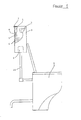
- a container 1 is mounted by a hanger 2 so as to be inverted within a cistern 3 with a dispensing device 4 according to this invention being mounted in the mouth of the container to dispense treatment liquid 5 confined within the container 1 into the water 6 within the cistern 3.
- water is admitted to the cistern through an inlet valve generally depicted at 7 and the toilet bowl 8 may be flushed by water from the cistern on the action of a flushing valve generally depicted at 9 connected to the bowl 8 by a down pipe 10.
- the arrangement and construction of the cistern and inlet and flushing valves is not relevant to this invention, but the invented device is designed to release automatically a small dose or quantity of liquid from the container on each flushing operation.
- the treatment liquid would be a disinfectant and may include a colouring agent to give a visible indication of water treatment.
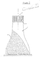
- FIGS 2 and 3 show the container 1 which is of a convenient bottle shape having a neck 11 defining a mouth 12 which is closed by a cap 13 engaged over the neck 11.
- the container body is provided with two pierced lugs 1 ⁇ for engagement with the hanger 2 which may be of any suitable shape or form to support the inverted container over the edge of the cistern 3 with the neck 11 of the container 1 being located at a position intermediate the high water level (WH) shown in Figure 2 and the low water level (WL) shown in Figure 5.
- WH high water level
- WL low water level
- the invented dispensing device 4 is mounted in the mouth 12 of the container 1 and comprises a seating member 14 and a control member 15. As shown in Figure 3, when the container 1 is closed by the cap 13 the dispensing device 4 is confined wholly within the mouth 12 and the treatment liquid 5 is confined within the container 1.
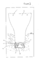
- the cap 13 is removed and in response to changes in the water level in the cistern between levels (WH) and (WL) through the intermediate level (WI) shown in Figure 4, the control member 15 is displaced relative to the seating member 14 between an inner limit position such as shown in Figures 4 and 6, and an outer limit position as shown in Figure 5.
- an inner limit position such as shown in Figures 4 and 6, and an outer limit position as shown in Figure 5.
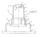
- the seating member 14 and the control member 15 are mouldings of suitable plastics material and are shown for clarity as integral although this is not essential.
- the seating member 14 has a substantially tubular hollow body 20 having an outer cylindrical wall portion 21 from which an annular flange portion 22 extends with three radial circumferentially spaced webs 23 extending between the outer faces of the wall portion 21 and the flange portion 22 to provide a reinforcement.
- a mounting flange 25 of cylindrical form extends from the annular flange 22 and terminates in an outwardly directed edge lip or rim 26.
- the mounting flange 25 and the edge lip 26 are complementary to the inner shape of the mouth and neck of the container for assembling the dispensing device to the container by an interference fit or by bonding or adhesive so that the dispensing device can be firmly mounted to the container and cannot be p ushed inwardly into the interior of the container.
- the body 20 of the seating member 14 also includes an inner wall portion 27 of substantially cylindrical form of less diameter than the outer wall portion 21 and which extends from an inclined shoulder portion 28.
- the inner free end of the body 20 terminates in a valve seating 29 that extends from a convergent end wall portion 30 of the body 20.
- the seating 29 is arranged co-axially with respect to the inner and outer wall portions 27,21 and provides an inlet port 31 arranged to be opened to the interior of the container in use for liquid within the container to be admitted to flow through an inner passageway 32 to a transfer port 33 defined partly by the re-entrant end face 47 of the valve seating 29.
- the control member 15 has a substantially hollow body 34 having an outer cylindrical wall portion 35 of a diameter for sliding sealing engagement with a limited axial length of the inner wall portion 27 of the seating member 14 as will be later described.
- the outer end of the wall portion 35 is formed with a radiused shoulder portion 36 that has an outer face for sealing engagement with the seating bead 24 of the seating member 14.
- the body 34 of the control member 15 also includes a substantially cylindrical outer flange 37 extending from the shoulder portion 36 and this terminates in an outwardly directed edge rim 38 having circumferentially spaced apart recesses 39.
- the rim 38 is arranged for engagement by the cap, and the recesses 39 are provided to facilitate flow of treatment liquid when discharged through the device as later explained.
- the body 34 of the control member 15 further includes an inner wall portion 40 of substantially cylindrical form that is of less diameter than the outer wall portion 35 but co-axial therewith. Extending between the inner and outer wall portions 40,35 there is a converging hip wall portion 41.
- the control member 15 also comprises a valve head 42 which is connected to the body 34 by a cylindrical neck 43 extending from a shoulder wall portion 44 that converges from the inner wall portion 40 and which extends up to the end wall portion 45 of the body to complete a partition wall exending between the seating member 14 and the control member 15.
- the valve head 42 has a frusto-conical outer face extending to the same cone angle as the adjacent face of the frusto-conical form of the valve seating 29 of the seating member 14 so that when the control member is displaced into the outward extreme position as shown in Figure 4, the adjacent frusto-conical faces of the seating 29 and the valve head 42 engage each other to close the inlet port 31.
- the valve head 42 is provided with a well recess 46 of conical shape, and this is for stablising and centering the control member 15 during operation and use when liquid may fill the well recess 46 to increase the overall mass of the control member 15 for gravity displacement to the position depicted in Figure 6.
- the face of the shoulder wall portion 44 of the control member 15 defines one annular wall of the transfer port 33 with the other wall of the port 33 being defined by the re-entrant annular end face 47 of the seating 29 as aforementioned.
- the seating 29 is provided with three axially extending and circumferentially spaced short grooves or recesses 48 for assisting in flow of liquid from the lower portion of the passageway 32 through the transfer port 33 whilst the inlet port 31 is open.
- the transfer port 33 leads to a transfer chamber 49 which is defined between the seating member 14 and the control mem ber 15 extending as a substantially annular chamber between the inner wall portion 27 of the seating and both the inner wall portion 40 and hip wall portion 41 of the control member.
- a transfer chamber 49 is closed at the outer end to confine admitted liquid therein as the outer wall portion 35 of the control member is in sealing engagement with the inner wall portion 27 of the seating member over a significant axial length.
- the transfer chamber 49 has an outlet port 50 which is defined by the seating member 14 at the intersection of the inner wall portion 27 and the shoulder portion 27 which diverges away from the inner wall portion 27 at such intersection.
- the port 50 leads to an outlet chamber 51 which extends between the outer wall portion 21 of the seating member 14 and the outer wall portion 35 of the control member 15.
- the seating member has three axially extending and cicumferentially spaced short grooves or recesses 52 for assisting in flow of liquid from the outlet port 50 and through the outlet chamber 51 when the control member 15 is displaced axially into the outward position with the outlet port 50 open as shown in Figure 5.
- the valve head 42 has a maximum diameter which is larger than the inlet port 31 whilst the neck 43 joining the valve head to the body 34 has a diameter which enables the neck 43 to move axially through the seating 29 between the extreme inner limit as just described when the seating bead 24 is engaged and the extreme outer limit when the valve head 42 seats on the valve seating 29 to close inlet port 31.
- the control member 15 is supported on and assembled to the seating member 14 for such relative axial movement for operation of the invented device.
- the relative axial lengths of the co-operating faces of the control member 15 and the seating member 14 which close the outlet port 50 and the transfer chamber 49 are arranged and designed so that when the control member is in the inner limit position as shown in Figure 6, then the outlet port 50 from the transfer chamber is closed, and as the control member moves to the outer limit position, then the outlet port 50 from the transfer chamber 49 is opened by disengagement of the co-operating faces when the inlet port 31 is closed by the valve head 42.
- the outlet port 50 is closed immediately prior to, or simultaneously with the opening of the inlet port 31 so that the transfer chamber 49 is isolated from water or the like lying near or within the outlet chamber 51.
- the hollow interior of the body 34 of the control member 15 provides an open void 53 into which air or water may enter during operation of the device on a change in water level so as to cause the axial displacement of the control member for dispensing the liquid and for recharging the transfer chamber for the next successive dispensing discharge.
- the container In use of the dispensing device as aforedescribed, the container is supported in the inverted position as shown in Figure 1, and the control member 15 is in the inward limit position as shown in Figures 3 and 6 until the cap is removed.
- the control member 15 When the control member 15 is at this inward position, the transfer chamber 49 is filled with liquid which flows through the inlet port 31 through the passageway 32 and through the transfer port 33 into the transfer chamber 49.
- control member 15 On outward displacement of the control member 15, the control member moves outwardly of the seating member 14 until it reaches a position when the valve head 42 seats within the seating 29 closing the inlet port 31 to prevent any further treatment liquid flowing into the transfer chamber 49.
- the small amount of treatment liquid contained within the transfer chamber 49 is then released from the transfer chamber 49 through the outlet port 50 which is then open as the hip shoulder 41 clears the inner wall portion 27 of the seating body 20.
- the liquid can then flow from between the outer wall portion 21 and the seating bead 24 of the seating member and the outer wall 35 with shoulder 36 to be discharged and dispensed into water confined within the cistern and as depicted in Figure 5.
- the particular shape of the control member outer faces with the rim and recesses is such as to provide a weir with effective flow distribution around the periphery of the control member.
- the control member Whilst the water level is at the intermediate level or higher level the mouth of the container with the device is submerged, the control member is maintained in the inward position with the transfer chamber being recharged ready for the next dispensing operation.
- this successive operation with the discharge and dispensing of the small volume of treatment liquid will proceed successively on each flushing/filling operation of the cistern with the liquid being dispensed during flushing and the device being recharged during cistern filling whilst no liquid can leak or be discharged from the container whilst the rim 39 is submerged below the level of the water.
- the seating member and the control member are of generally stepped cylindrical tubular form with the transfer chamber being of generally annular form of which the volume may be designed in accordance with the selected axial length and relative diameters of the inner wall portions of the respective seating and control members.
- the cross section of both the seating and the control members may not necessarily be circular and a square or rectangular cross sectional shape could be used.
- the seating and control members are assembled together and supported by the frusto-conical form of valve head.
- the two members could be assembled together for limited relative movement by inter-engaging ribs or grooves extending axially between the two members, for instance in the region of the outlet chamber.
- the control member could be supported for relative movement with respect to the seating member by a spider support located between the outer mounting flange of the seating and the flange of the control member.
- control member is des igned to provide the void chamber for entrapping air and/or water for the responsive reaction of the control member on change of water level. Additionally, the control member has the particular shape to provide the weir over which the treatment liquid is discharged.
- the invented dispensing device has other applications for dispensing small quantities of liquid from a container which may be supported in an inverted manner.
- Another suitable application for the invented dispensing device is for manual use in obtaining a limited quantity of soap or shampoo that might be confined within the container for discharge by manual operation of the control member which is merely pushed upwards by a hand held underneath the device to receive the quantity of liquid therein.
- Typical of such an application is for dispensing liquid soap or shower gel in an ablutionary shower installation wherein a container with the invented dispensing device may be supported for operation of the dispensing device when required.
- the control member remains in the outward limit position when the liquid has been discharged, the dispensing device will operate as an automatic shut-off arrangement for single shot dispensing when the control member is pressed upwardly into the inward limit position.
- the invented dispensing device is simple both in construction and in use, and it has significant meritous features as referred to herein.
Landscapes
- Health & Medical Sciences (AREA)
- Public Health (AREA)
- Epidemiology (AREA)
- Life Sciences & Earth Sciences (AREA)
- Engineering & Computer Science (AREA)
- Hydrology & Water Resources (AREA)
- Water Supply & Treatment (AREA)
- Closures For Containers (AREA)
Applications Claiming Priority (2)
| Application Number | Priority Date | Filing Date | Title |
|---|---|---|---|
| GB08622707A GB2195368A (en) | 1986-09-20 | 1986-09-20 | Device for dispensing a quantity of liquid from a container |
| GB8622707 | 1986-09-20 |
Publications (1)
| Publication Number | Publication Date |
|---|---|
| EP0261882A1 true EP0261882A1 (de) | 1988-03-30 |
Family
ID=10604531
Family Applications (1)
| Application Number | Title | Priority Date | Filing Date |
|---|---|---|---|
| EP87308262A Withdrawn EP0261882A1 (de) | 1986-09-20 | 1987-09-18 | Abgabevorrichtung einer Flüssigkeitsmenge aus einem Behälter |
Country Status (2)
| Country | Link |
|---|---|
| EP (1) | EP0261882A1 (de) |
| GB (1) | GB2195368A (de) |
Cited By (1)
| Publication number | Priority date | Publication date | Assignee | Title |
|---|---|---|---|---|
| WO1999029971A1 (es) | 1997-12-04 | 1999-06-17 | Francisco Alonso Fullola | Dosificador automatico para productos higienico-desinfectantes para uso cotidiano para las personas |
Families Citing this family (4)
| Publication number | Priority date | Publication date | Assignee | Title |
|---|---|---|---|---|
| GB2243378B (en) * | 1990-04-24 | 1994-07-06 | Anthony John Crabtree | Dispensing container |
| GB2298878A (en) * | 1995-03-14 | 1996-09-18 | Roger Pitman | Dispensing unit for a toilet cistern |
| EP1386040B1 (de) | 2001-05-11 | 2005-10-12 | S. C. Johnson & Son, Inc. | Abwärtshub-spender |
| GB2402945B (en) | 2003-06-16 | 2008-02-20 | Jeyes Group Ltd | A liquid dispensing device |
Citations (4)
| Publication number | Priority date | Publication date | Assignee | Title |
|---|---|---|---|---|
| US3841524A (en) * | 1973-03-05 | 1974-10-15 | Northwest Sanitation Prod Inc | Automatic liquid dispenser for an inverted bottle |
| US4285074A (en) * | 1979-12-20 | 1981-08-25 | Enjoyable Products, Inc. | Refillable dispensing apparatus |
| US4294369A (en) * | 1979-12-20 | 1981-10-13 | Pierre Racine | Liquid dispensing receptacle |
| EP0141687A2 (de) * | 1983-09-20 | 1985-05-15 | Societe Eparco S.A. | Flüssigkeitsverteilvorrichtung geeignet zum Einbringen in einem Spülkasten |
Family Cites Families (6)
| Publication number | Priority date | Publication date | Assignee | Title |
|---|---|---|---|---|
| US3908209A (en) * | 1974-04-15 | 1975-09-30 | Owens Illinois Inc | Fluid dispensing apparatus |
| US3945062A (en) * | 1975-01-24 | 1976-03-23 | Corsette Douglas Frank | Toilet chemical dispenser |
| DE2748552C2 (de) * | 1977-10-28 | 1987-03-19 | Georg 7800 Freiburg Schreieder | Vorrichtung zum dosierten Zuführen eines fließfähigen Zugabemittels in Spülwassersysteme od. dgl. |
| US4429809A (en) * | 1980-04-25 | 1984-02-07 | Airwick Industries, Inc. | Device for the metered release of an active ingredient |
| GB2167041B (en) * | 1984-11-21 | 1988-03-02 | Kemstech Cleansing Products En | Dispensing valve assembly |
| GB8527695D0 (en) * | 1985-11-09 | 1985-12-11 | Reckitt & Colmann Prod Ltd | Fluid dispenser |
-
1986
- 1986-09-20 GB GB08622707A patent/GB2195368A/en not_active Withdrawn
-
1987
- 1987-09-18 EP EP87308262A patent/EP0261882A1/de not_active Withdrawn
Patent Citations (4)
| Publication number | Priority date | Publication date | Assignee | Title |
|---|---|---|---|---|
| US3841524A (en) * | 1973-03-05 | 1974-10-15 | Northwest Sanitation Prod Inc | Automatic liquid dispenser for an inverted bottle |
| US4285074A (en) * | 1979-12-20 | 1981-08-25 | Enjoyable Products, Inc. | Refillable dispensing apparatus |
| US4294369A (en) * | 1979-12-20 | 1981-10-13 | Pierre Racine | Liquid dispensing receptacle |
| EP0141687A2 (de) * | 1983-09-20 | 1985-05-15 | Societe Eparco S.A. | Flüssigkeitsverteilvorrichtung geeignet zum Einbringen in einem Spülkasten |
Cited By (1)
| Publication number | Priority date | Publication date | Assignee | Title |
|---|---|---|---|---|
| WO1999029971A1 (es) | 1997-12-04 | 1999-06-17 | Francisco Alonso Fullola | Dosificador automatico para productos higienico-desinfectantes para uso cotidiano para las personas |
Also Published As
| Publication number | Publication date |
|---|---|
| GB8622707D0 (en) | 1986-10-29 |
| GB2195368A (en) | 1988-04-07 |
Similar Documents
| Publication | Publication Date | Title |
|---|---|---|
| US8998036B2 (en) | Dispenser and refill unit | |
| AU2009315390B2 (en) | A bottle with a tamper-proof cap | |
| US4064572A (en) | Level actuated apparatus for delivering chemicals | |
| CN102216170B (zh) | 减压阀、具有该减压阀的容器和再装填单元 | |
| US2688754A (en) | Cleanser dispenser | |
| CA1239757A (en) | Automatic dispenser for disinfectant and bowl cleaning fluid | |
| US2913734A (en) | Liquid dispensing apparatus | |
| US3908209A (en) | Fluid dispensing apparatus | |
| US3945062A (en) | Toilet chemical dispenser | |
| US4285074A (en) | Refillable dispensing apparatus | |
| EP0261882A1 (de) | Abgabevorrichtung einer Flüssigkeitsmenge aus einem Behälter | |
| US4189793A (en) | Automatic liquid dispenser for an inverted bottle | |
| US6748610B2 (en) | In-tank dispenser with flexible supported valve head | |
| US4036407A (en) | Dosing valve | |
| US5136732A (en) | Commode flushing apparatus | |
| EP1386040B1 (de) | Abwärtshub-spender | |
| KR102260720B1 (ko) | 양변기용 세정액 자동 분배기 | |
| JPS62113020A (ja) | 流体デイスペンサ | |
| WO2007141704A1 (en) | A dispenser for dispensing a dosing liquid into a toilet cistern | |
| US4949403A (en) | Automatic dispenser for flush tanks | |
| US4142260A (en) | Chemical dispenser for flush type water tank toilets | |
| CA2411235A1 (en) | Detergent dispenser | |
| CA1046705A (en) | Dispensation of concentrated solution into toilet flush tank | |
| ITMI951251A1 (it) | Cassetta di cacciata per wc | |
| HU213061B (en) | Portioning cistern, particularly for water saving flushing toilets |
Legal Events
| Date | Code | Title | Description |
|---|---|---|---|
| PUAI | Public reference made under article 153(3) epc to a published international application that has entered the european phase |
Free format text: ORIGINAL CODE: 0009012 |
|
| 17P | Request for examination filed |
Effective date: 19870918 |
|
| AK | Designated contracting states |
Kind code of ref document: A1 Designated state(s): AT BE CH DE ES FR GR IT LI LU NL SE |
|
| STAA | Information on the status of an ep patent application or granted ep patent |
Free format text: STATUS: THE APPLICATION IS DEEMED TO BE WITHDRAWN |
|
| 18D | Application deemed to be withdrawn |
Effective date: 19900403 |
|
| RIN1 | Information on inventor provided before grant (corrected) |
Inventor name: BARRATT, MARK |