EP0261909A2 - Dispositif pour la suspension de tubages - Google Patents
Dispositif pour la suspension de tubages Download PDFInfo
- Publication number
- EP0261909A2 EP0261909A2 EP87308330A EP87308330A EP0261909A2 EP 0261909 A2 EP0261909 A2 EP 0261909A2 EP 87308330 A EP87308330 A EP 87308330A EP 87308330 A EP87308330 A EP 87308330A EP 0261909 A2 EP0261909 A2 EP 0261909A2
- Authority
- EP
- European Patent Office
- Prior art keywords
- hanger
- ring
- landing ring
- split
- casing
- Prior art date
- Legal status (The legal status is an assumption and is not a legal conclusion. Google has not performed a legal analysis and makes no representation as to the accuracy of the status listed.)
- Withdrawn
Links
Images



Classifications
-
- E—FIXED CONSTRUCTIONS
- E21—EARTH OR ROCK DRILLING; MINING
- E21B—EARTH OR ROCK DRILLING; OBTAINING OIL, GAS, WATER, SOLUBLE OR MELTABLE MATERIALS OR A SLURRY OF MINERALS FROM WELLS
- E21B33/00—Sealing or packing boreholes or wells
- E21B33/02—Surface sealing or packing
- E21B33/03—Well heads; Setting-up thereof
- E21B33/04—Casing heads; Suspending casings or tubings in well heads
- E21B33/043—Casing heads; Suspending casings or tubings in well heads specially adapted for underwater well heads
Definitions
- This invention relates to casing hanger systems, and more particularly, but not exclusively, to mudline hanger systems for strings of relatively small diameter (for example, 9 5/8 inches or approximately 245 millimetres).
- casings refers to the tubes or pipes which extend more or less vertically underground in oil and gas wells, and the term “strings” refers to the extended end-to-end assembles of such tubes or pipes.
- strings refers to the extended end-to-end assembles of such tubes or pipes.
- mudline refers to the sea bottom, i.e. the interface between the geological materials (usually sediments) and the sea water.
- jack-up drilling systems use casing hangers which can suspend a coaxial series of casing strings such that their combined weight is suspended at the mudline. This allows the drilling rig to operate in deeper than normal waters, and provides for disconnection and removal of equipment above the mudline when the drilling rig moves from one drilling location to another drilling location.
- Casing strings of larger diameter have sufficient annular space to allow the use of solid hangers, normally in the form of a metal annulus which is suspended on an internal shoulder on the outer casing and in turn suspends the inner casing via an external shoulder on the inner casing.
- Casing strings of smaller diameter may make use of a split ring hanger to suspend the innermost string.
- a split ring hanger may also be referred to as a "split landing ring”.
- split ring hangers have certain disadvantages, such as a reduced hoop strength when in their expanded operating condition.
- a casing hanger system for coaxially suspending an inner casing string from an outer casing
- said casing hanger system including a running hanger body, a receiving hanger, and a split landing ring
- the running hanger body being adapted to form part of said inner casing string
- the receiving hanger being adapted to form part of said outer casing
- the split landing ring being generally tubular in overall shape and having at least one generally axial division
- said ring being biassed to a circumferentially expanded condition while being capable of being forced against said bias to a circumferentially contracted condition
- the outer surface of said split landing ring and the inner surface of said receiving hanger having complementary groove and shoulder profiles capable of mutual engagement to prevent downward movement of the split landing ring relative to the receiving hanger when said profiles are mutually engaged
- means on said running hanger body to limit axial movement of said split landing ring in its circumferentially contracted condition relative to the running hanger body while the running hanger body carrying the split landing ring is descending towards the receiving hang
- Said complementary groove and shoulder profiles preferably consist of at least one circumferential groove on the inner surface of the receiving hanger and an equal number of circumferential grooves on the outer surface of the split landing ring.
- the temporary restraint may be a setting ring in the form of a split ring naturally biassed into a circumferentially contracted condition but capable of being forced against said natural bias to a circumferentially expanded condition.
- the setting ring may be initially mounted between the lower edge of one of the cam surfaces on the running hanger body and the upper edge of an annular ledge formed on the inner surface of the split landing ring.
- the temporary restraint may alternatively be a shear ring initially secured around the lower edge of the upper cam surface by at least one shear pin to present an obstruction to upward movement of the split landing ring relative to the running hanger body and hence to provide said temporary restraint, initiation of a downward movement of the running hanger body relative to the split landing ring when said profiles are engaged causing the or each shear pin to shear by upward pressure of the split landing ring against the shear ring to allow said downward movement to proceed.
- the upper end termination of the annular recess in the running hanger body is preferably a discrete load ring initially formed as an annular component separate from the remainder of the running hanger body and subsequently secured thereto, preferably by a screw threaded connection.
- the lower end termination of the annular recess in the running hanger body is preferably a discrete retainer gland initially formed as an annular component separate from the remainder of the running hanger body and subsequently secured thereto, preferably by a screw-threaded connection.
- the split landing ring requires to be brought into its circumferentially contracted condition against its natural bias for insertion into the outer casing of which the receiving hanger forms part. If the trailing end of the split landing ring (the upper end which last enters the casing) circumferentially contracts less than the leading end of the ring (the lower end which first enters the casing), the ring is liable to be damaged in the process of being inserted into the casing.
- This problem is avoided in accordance with a subsidiary feature of the present invention by providing one or more ramps on the outer circumference of the split landing ring, these ramps being inclined relative to the central axis of the ring such that they wedge against the rim of the outer casing on insertion of the ring and so apply to the ring radially inwardly directed forces which cause the ring to contract against its natural bias.
- the ramps are dsposed on the ring such that the radial plane through the points on the ramps which first make contact with the rim of the outer casing is not below the radial plane through the sectional neutral axis of the ring.
- sectional neutral axis is used herein to define the axial position along the ring at which an applied radial force will contract the ring circumferentially to an equal extent above and below that position. Thus if a radial force is applied to the ring above the radial plane through the sectional neutral axis the upper part of the ring will contract to a greater extent than the lower part.
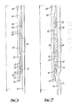
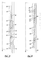
- each of these three Figures shows an axial section of the respective components and assemblies; since these components are circularly symmetrical about the central longitudinal axis, only the right halves of the sections are shown for simplicity.
- the central longitudinal axis is denoted by a vertical chain-dash line (corresponding to the normally vertical alignment of these components and assemblies in use as part of a casing hanger system).
- a running hanger body 20 is an elongated and generally tubular component which is adapted to form part of an inner casing string.
- the running hanger body 20 has a lower end pipe thread 22 by which the body 20 is coupled to a lower casing 24.
- the running hanger body 20 is similarly coupled to an upper casing 26 by means of an upper end pipe thread (not shown).
- the inner casing string 24 and 26, incorporating the running hanger body 20, is capable of controlled vertical movement.
- the running hanger body 20 has an external annular recess 28 with an upper end termination in the form of load ring 30, and lower end termination in the form of a retainer gland 32.
- the load ring 30 is secured to the running hanger body 20 by a screw-threaded connection 36.
- the retainer gland 32 is secured to the running hanger body 20 by a screw-threaded connection 38.
- a split landing ring 40 is generally tubular in overall shape and fabricated from a resilient material.
- the ring 40 has a generally axial division in the form of an end-to-end slot (not illustrated) extending completely through the radial cross-section of the ring 40.
- the combination of the resilience of the material of the ring 40 with the full-length, full-depth axial slot results in the ring 40 being naturally biassed to a circumferentially expanded condition in which the axial slot has a maximum width and the total circumference of the ring 40, including the axial slot, is at a maximum. Nevertheless, the ring 40 is capable of being forced against this natural bias to a slot has a lesser or zero width.
- the axial length of the split landing ring 40 is significantly less than the axial length of the annular recess 28 between the upper and lower end termination of the recess 28 (respectively the load ring 30 and the retainer gland 36). This permits limited relative axial movement between the split landing ring 40 and the running hanger body 20 while preventing axial separation of the split landing ring 40 from the running hanger body 20.
- a temporary restraint in the form of a setting ring 42 holds the split landing ring 40 adjacent the lower end termination 32 while the ring 40 is constrained to its circumferentially contracted condition by an outer casing 44.
- the setting ring 42 is initially mounted between the lower edge of the lower one 46 of an axially spaced pair of annular cam surfaces 46 and 48 formed within the annular recess 28, and the upper edge of an annular ledge 50 formed on the inner surface of the split landing ring 40.
- a receiving hanger 52 (Fig. 2) which is coupled to the outer casing 44 by a standard tapered pipe thread connection (not illustrated).
- the receiving hanger 52 is similarly adapted to be coupled to a further downward extension 54 of the outer casing by a further tapered pipe thread connection 56.
- the upper end of the outer surface of the split landing ring 40 and the inside surface of the central length of the receiving hanger 52 have respective complementary groove and shoulder profiles 58 and 60.
- these profiles 58 and 60 each take the form of four circumferential grooves at equal axial spacings.
- the upper side of each groove in the profile 58 and the lower side of each groove in the profile 60 form shoulders which mutually engage as shown in Fig. 2 to allow the split landing ring 40 to be suspended from the receiving hanger 52.
- the sides of the grooves opposite these shoulders are conically tapered to broaden towards the respective surface to provide a lead-in and to facilitate the interengagement of the profiles 58 and 60 in a relatively gradual manner as they move into mutual axial alignment.
- the circumferential expansion of the split landing ring 40 brings the ledge 50 on the inner surface of the ring 40 at least as radially far out from the central axis as the annular outer surface of the lower cam 46, and this initiates the release of the temporary restraint hitherto provided by the setting ring 42.
- the split landing ring 40 is positively retained in its circumferentially expanded condition by means of the upper annular cam 48 forcing the upper end of the ring 40 against the inside of the receiving hanger 52, and also by means of the lower annular cam 46 forcing the lower end of the ring 40 against the inside of the receiving hanger 52 (partly through the expanded setting ring 42 and partly through the lower edge of the ledge 50).
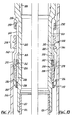
- FIGs. 4, 5 and 6 illustrate a second embodiment of the invention in the same part-sectional convention employed for the first embodiment of Figs. 1 - 3.
- the major difference between the first and second embodiments is in the form of the temporary restraint, being a setting ring in the first embodiment and a shear ring in the second embodiment.
- Those parts of the second embodiment which correspond directly or functionally to identical or functionally equivalent parts of the first embodiment are given reference numerals in Figs. 4, 5 and 6 which are the equivalent reference numerals used in Figs. 1, 2 and 3, but prefixed by a "1".
- Fig. 4 the setting ring 42 of Fig. 1 is no longer employed, and is effectively integrated into the inner surface of the split landing ring 140, with a chamfered upper edge to facilitate initial reaction with the leading lower edge of the lower annular cam 146.
- the temporary restraint of the second embodiment is provided by a shear ring 162 formed of a relatively inelastic material without axial division so as to have a constant effective circumference under all normal conditions.
- the shear ring 162 is initially secured to the leading lower edge of the upper annular cam 148 by means of one or more radially aligned shear pins 164.
- Fig. 5 shows the second embodiment at the stage corresponding to Fig. 2. At this point, further downward movement of the running hanger body 120 relative to the split landing ring 140 is temporarily restrained by the upper edge of the ring 140 bearing against the lower edge of the shear ring 162.
- This temporary restraint is removed by shearing of the or each shear pin 164 to allow the shear ring 162 to slide up the outer face of the upper annular cam 148 under the upward force applied by the upper edge of the split landing ring 140.
- the running hanger body 120 continues its downward movement relative to the receiving hanger 152 until the shear ring 162 abuts the load ring 130, and since the split landing ring 140 has been pushing the shear ring 162, this abutment terminates the downward movement of the running hanger body 120 as shown in Fig. 6.
- the axial length of the annular recess 128, and in particular, the axial length of the upper annular cam 148 is suitably increased.
- Fig. 6 (as shown in Fig. 3) the running hanger body 120 is suspended from the receiving hanger 152 via the intermediate split landing ring 140 which acts as a split ring hanger.
- the split landing ring 140 is positively retained in its casing suspension position by cam forces acting outwards from the cams 146 and 148 at two axially spaced-apart positions on the ring 140, near either end of the ring 140 and axially on either side of the complementary profiles 158 and 160.
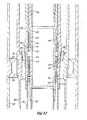
- each of these Figures is a radial section of one side only of the circularly symmetrical components and assemblies of the third embodiment of the invention, following the convention employed in Figs. 1 - 6.
- these sections are alternately left and right half sections, placed in mutual alignment for ease of comparison of the successive steps in procedures illustrated in Figs. 7 - 11.
- the component numbering convention of Figs. 7 - 11 relates to the reference numerals of Figs. 1 - 3 in a manner similar to the relationship of Figs. 4 - 6 to Figs. 1 - 3; those parts of the third embodiment which correspond directly or functionally to equivalent parts of the first embodiment are gven reference numerals which are the equivalent reference numerals used in Figs. 1 - 3, but prefixed by a "2" reference.
- Fig. 7 shows the assembly of the running hanger body 220 and the split landing ring 240 about to commence insertion into the top end of the outer casing 244.
- the outer surface of the ring 240 is provided with a circumferentially distributed series of longitudinal ramps 270 tapering outwardly with increasing height up the ring 240.
- Initial circumferential constraint is applied to the split landing ring 240 by providing the retainer gland 232 with a circumferential lip 234 which sets a radial limit to movement of the lower end of the ring 240.
- Fig. 10 show a configuration corresponding to Fig. 2, in which the complementary profiles 258 and 260 are fully engaged, the temporary restraint provided by the setting ring 242 is about to be released, and movement of the running hanger body 220 relative to the now-restrained split landing ring 240 is about to commence.
- Fig. 11 shows the final configuration reached during installation of the third embodiment.
- the split landing ring 240 is positively retained in its circumferentially expanded condition against the inside surface of the receiving hanger 252, with the complementary profiles 258 and 260 in mutual engagement, by means of the upper annular cam 248 forcing out the upper end of the ring 240, and the lower annular cam 246 forcing out the lower end of the ring 240.
- the running hanger body 220 and the inner casing 224 depending from the body 220 are suspended from the receiving hanger 252 through the intermediary of the split landing ring 240 which thereby acts as split ring hanger.
- the positive positional locking of the ring 240 imparts a mechanical function equivalent to a solid ring hanger, at least insofar as the hoop strength of the hanger is relied upon in normal operation.
- the inner casing string and the outer casing can be installed with a high degree of concentricity and parallelism, which can be maintained throughout operational use of the casing hanger system.
- FIG. 12 shows a fourth embodiment of the invention which is generally similar to the third embodiment (of Figs. 7 - 11).
- Fig. 12 is a full-width diametral section, but the previous component numbering convention is still followed, in that parts corresponding to those in Fig. 1 are given the same reference numeral, but prefixed by a "3".
- Fig. 12 shows part of a casing hanger system for four concentric casings 324 plus 326, 354, 380, and 382.
- the casings 324 and 326 form part of an inner casing string, and are screw-coupled in to either end of a running hanger body 320.
- the running hanger body 320 is suspended from a receiving hanger 352 through the intermediary of a split landing ring 340.
- the receiving hanger 352 is suspended in turn from an internal shoulder 384 on the second-outermost casing 380 through the intermediary of a solid hanger ring 386.
- the solid hanger ring 386 has a number of end-to-end through passages 388 to permit the flow of fluids up or down between the casings 354 and 380.
- An internal shoulder 390 on the outermost casing 382 radially engages a circumferentially distributed series of ribs 392 secured to the outside of the second-outermost casing 380.
- Fig. 12 particularly illustrates the application of the invention to casing hanger systems including casings of relatively small diameter and having minimal annular separation such that conventional solid ring hangers would be impracticable or impossible.
Landscapes
- Life Sciences & Earth Sciences (AREA)
- Engineering & Computer Science (AREA)
- Geology (AREA)
- Mining & Mineral Resources (AREA)
- Physics & Mathematics (AREA)
- Environmental & Geological Engineering (AREA)
- Fluid Mechanics (AREA)
- General Life Sciences & Earth Sciences (AREA)
- Geochemistry & Mineralogy (AREA)
- Earth Drilling (AREA)
- Sampling And Sample Adjustment (AREA)
Applications Claiming Priority (8)
| Application Number | Priority Date | Filing Date | Title |
|---|---|---|---|
| GB8622859 | 1986-09-23 | ||
| GB868622859A GB8622859D0 (en) | 1986-09-23 | 1986-09-23 | Casing hanger system |
| GB8626046 | 1986-10-31 | ||
| GB868626046A GB8626046D0 (en) | 1986-10-31 | 1986-10-31 | Casing hanger system |
| GB8705371 | 1987-03-07 | ||
| GB878705371A GB8705371D0 (en) | 1987-03-07 | 1987-03-07 | Spring-loaded ring |
| GB8709430 | 1987-04-21 | ||
| GB878709430A GB8709430D0 (en) | 1987-04-21 | 1987-04-21 | Spring-loaded ring |
Publications (2)
| Publication Number | Publication Date |
|---|---|
| EP0261909A2 true EP0261909A2 (fr) | 1988-03-30 |
| EP0261909A3 EP0261909A3 (fr) | 1989-03-22 |
Family
ID=27449817
Family Applications (1)
| Application Number | Title | Priority Date | Filing Date |
|---|---|---|---|
| EP87308330A Withdrawn EP0261909A3 (fr) | 1986-09-23 | 1987-09-21 | Dispositif pour la suspension de tubages |
Country Status (2)
| Country | Link |
|---|---|
| EP (1) | EP0261909A3 (fr) |
| NO (1) | NO873953L (fr) |
Cited By (6)
| Publication number | Priority date | Publication date | Assignee | Title |
|---|---|---|---|---|
| US4911244A (en) * | 1989-06-30 | 1990-03-27 | Cameron Iron Works Usa, Inc. | Marine casing suspension apparatus |
| US4919460A (en) * | 1989-02-06 | 1990-04-24 | Vetco Gray Inc. | Wellhead casing hanger support mechanism |
| GB2237308A (en) * | 1989-10-18 | 1991-05-01 | Nat Oilwell | Casing suspension system |
| US5620052A (en) * | 1995-06-07 | 1997-04-15 | Turner; Edwin C. | Hanger suspension system |
| CN103967436A (zh) * | 2014-05-19 | 2014-08-06 | 江苏金石科技有限公司 | 水下井口泥线悬挂器 |
| US12188322B2 (en) | 2021-08-06 | 2025-01-07 | Baker Hughes Oilfield Operations Llc | Lockdown ring using a self-locking wedge |
Family Cites Families (5)
| Publication number | Priority date | Publication date | Assignee | Title |
|---|---|---|---|---|
| US4295665A (en) * | 1979-09-04 | 1981-10-20 | Petroleum Designers, Inc. | Well casing suspension system |
| US4355825A (en) * | 1980-10-15 | 1982-10-26 | Cameron Iron Works, Inc. | Mudline suspension system |
| US4468055A (en) * | 1982-05-03 | 1984-08-28 | Dril Quip, Inc. | Wellhead apparatus |
| US4534583A (en) * | 1982-11-12 | 1985-08-13 | Combustion Engineering, Inc. | Mudline casing hanger assembly |
| US4607865A (en) * | 1984-10-16 | 1986-08-26 | Vetco Offshore Industries, Inc. | Connector, ratcheting type |
-
1987
- 1987-09-21 EP EP87308330A patent/EP0261909A3/fr not_active Withdrawn
- 1987-09-22 NO NO873953A patent/NO873953L/no unknown
Cited By (8)
| Publication number | Priority date | Publication date | Assignee | Title |
|---|---|---|---|---|
| US4919460A (en) * | 1989-02-06 | 1990-04-24 | Vetco Gray Inc. | Wellhead casing hanger support mechanism |
| US4911244A (en) * | 1989-06-30 | 1990-03-27 | Cameron Iron Works Usa, Inc. | Marine casing suspension apparatus |
| GB2237308A (en) * | 1989-10-18 | 1991-05-01 | Nat Oilwell | Casing suspension system |
| US5127478A (en) * | 1989-10-18 | 1992-07-07 | National-Oilwell | Casing suspension system |
| GB2237308B (en) * | 1989-10-18 | 1993-07-07 | Nat Oilwell | Casing suspension system |
| US5620052A (en) * | 1995-06-07 | 1997-04-15 | Turner; Edwin C. | Hanger suspension system |
| CN103967436A (zh) * | 2014-05-19 | 2014-08-06 | 江苏金石科技有限公司 | 水下井口泥线悬挂器 |
| US12188322B2 (en) | 2021-08-06 | 2025-01-07 | Baker Hughes Oilfield Operations Llc | Lockdown ring using a self-locking wedge |
Also Published As
| Publication number | Publication date |
|---|---|
| EP0261909A3 (fr) | 1989-03-22 |
| NO873953D0 (no) | 1987-09-22 |
| NO873953L (no) | 1988-03-24 |
Similar Documents
| Publication | Publication Date | Title |
|---|---|---|
| US4665979A (en) | Metal casing hanger seal with expansion slots | |
| US4641708A (en) | Casing hanger locking device | |
| US4595053A (en) | Metal-to-metal seal casing hanger | |
| US7040407B2 (en) | Collet load shoulder | |
| US4932472A (en) | Packoff with flexible section for casing hanger | |
| EP0137335A2 (fr) | Dispositif de suspension de tubage pour tête de puits immergée | |
| US4903992A (en) | Locking ring for oil well tool | |
| EP0417365B1 (fr) | Dispositif de suspension de tubage de puits immergé | |
| GB2274477A (en) | Positive lock-down for wellhead seal | |
| GB2079821A (en) | Tangentially loaded slip assembly | |
| US5620052A (en) | Hanger suspension system | |
| GB2235229A (en) | Adjustable sub for well conduits | |
| CA2664979C (fr) | Methode et appareil pour l'ancrage d'outils de fond de puits | |
| CA2087928C (fr) | Ensemble de suspension | |
| GB2270940A (en) | Casing hanger running tool | |
| GB2275748A (en) | Pipe connector with segmented latches | |
| EP0261909A2 (fr) | Dispositif pour la suspension de tubages | |
| US4893842A (en) | Wellhead tieback system with locking dogs | |
| US4465133A (en) | Casing hanger collet | |
| US5094297A (en) | Casing weight set seal ring | |
| US3188118A (en) | Pipe holding apparatus | |
| US10538985B2 (en) | Stackable support system and method | |
| EP0378040B1 (fr) | Outils pour poser et récupérer une suspension de tubage | |
| RU2840601C1 (ru) | Пакер и способ установки пакера внутри обсадной колонны скважины | |
| US9617820B2 (en) | Flexible emergency hanger and method of installation |
Legal Events
| Date | Code | Title | Description |
|---|---|---|---|
| PUAI | Public reference made under article 153(3) epc to a published international application that has entered the european phase |
Free format text: ORIGINAL CODE: 0009012 |
|
| AK | Designated contracting states |
Kind code of ref document: A2 Designated state(s): FR GB IT |
|
| PUAL | Search report despatched |
Free format text: ORIGINAL CODE: 0009013 |
|
| AK | Designated contracting states |
Kind code of ref document: A3 Designated state(s): FR GB IT |
|
| STAA | Information on the status of an ep patent application or granted ep patent |
Free format text: STATUS: THE APPLICATION IS DEEMED TO BE WITHDRAWN |
|
| 18D | Application deemed to be withdrawn |
Effective date: 19890923 |
|
| RIN1 | Information on inventor provided before grant (corrected) |
Inventor name: VAN BILDERBEEK, BERNARD HERMAN |