EP0261917B1 - Détection de changements dans des données vidéo - Google Patents
Détection de changements dans des données vidéo Download PDFInfo
- Publication number
- EP0261917B1 EP0261917B1 EP87308347A EP87308347A EP0261917B1 EP 0261917 B1 EP0261917 B1 EP 0261917B1 EP 87308347 A EP87308347 A EP 87308347A EP 87308347 A EP87308347 A EP 87308347A EP 0261917 B1 EP0261917 B1 EP 0261917B1
- Authority
- EP
- European Patent Office
- Prior art keywords
- video
- video signal
- data
- signal
- change
- Prior art date
- Legal status (The legal status is an assumption and is not a legal conclusion. Google has not performed a legal analysis and makes no representation as to the accuracy of the status listed.)
- Expired - Lifetime
Links
Images




Classifications
-
- G—PHYSICS
- G08—SIGNALLING
- G08B—SIGNALLING SYSTEMS, e.g. PERSONAL CALLING SYSTEMS; ORDER TELEGRAPHS; ALARM SYSTEMS
- G08B13/00—Burglar, theft or intruder alarms
- G08B13/18—Actuation by interference with heat, light, or radiation of shorter wavelength; Actuation by intruding sources of heat, light, or radiation of shorter wavelength
- G08B13/189—Actuation by interference with heat, light, or radiation of shorter wavelength; Actuation by intruding sources of heat, light, or radiation of shorter wavelength using passive radiation detection systems
- G08B13/194—Actuation by interference with heat, light, or radiation of shorter wavelength; Actuation by intruding sources of heat, light, or radiation of shorter wavelength using passive radiation detection systems using image scanning and comparing systems
- G08B13/196—Actuation by interference with heat, light, or radiation of shorter wavelength; Actuation by intruding sources of heat, light, or radiation of shorter wavelength using passive radiation detection systems using image scanning and comparing systems using television cameras
- G08B13/19602—Image analysis to detect motion of the intruder, e.g. by frame subtraction
-
- G—PHYSICS
- G08—SIGNALLING
- G08B—SIGNALLING SYSTEMS, e.g. PERSONAL CALLING SYSTEMS; ORDER TELEGRAPHS; ALARM SYSTEMS
- G08B13/00—Burglar, theft or intruder alarms
- G08B13/18—Actuation by interference with heat, light, or radiation of shorter wavelength; Actuation by intruding sources of heat, light, or radiation of shorter wavelength
- G08B13/189—Actuation by interference with heat, light, or radiation of shorter wavelength; Actuation by intruding sources of heat, light, or radiation of shorter wavelength using passive radiation detection systems
- G08B13/194—Actuation by interference with heat, light, or radiation of shorter wavelength; Actuation by intruding sources of heat, light, or radiation of shorter wavelength using passive radiation detection systems using image scanning and comparing systems
- G08B13/196—Actuation by interference with heat, light, or radiation of shorter wavelength; Actuation by intruding sources of heat, light, or radiation of shorter wavelength using passive radiation detection systems using image scanning and comparing systems using television cameras
- G08B13/19602—Image analysis to detect motion of the intruder, e.g. by frame subtraction
- G08B13/19604—Image analysis to detect motion of the intruder, e.g. by frame subtraction involving reference image or background adaptation with time to compensate for changing conditions, e.g. reference image update on detection of light level change
-
- G—PHYSICS
- G08—SIGNALLING
- G08B—SIGNALLING SYSTEMS, e.g. PERSONAL CALLING SYSTEMS; ORDER TELEGRAPHS; ALARM SYSTEMS
- G08B13/00—Burglar, theft or intruder alarms
- G08B13/18—Actuation by interference with heat, light, or radiation of shorter wavelength; Actuation by intruding sources of heat, light, or radiation of shorter wavelength
- G08B13/189—Actuation by interference with heat, light, or radiation of shorter wavelength; Actuation by intruding sources of heat, light, or radiation of shorter wavelength using passive radiation detection systems
- G08B13/194—Actuation by interference with heat, light, or radiation of shorter wavelength; Actuation by intruding sources of heat, light, or radiation of shorter wavelength using passive radiation detection systems using image scanning and comparing systems
- G08B13/196—Actuation by interference with heat, light, or radiation of shorter wavelength; Actuation by intruding sources of heat, light, or radiation of shorter wavelength using passive radiation detection systems using image scanning and comparing systems using television cameras
- G08B13/19634—Electrical details of the system, e.g. component blocks for carrying out specific functions
-
- H—ELECTRICITY
- H04—ELECTRIC COMMUNICATION TECHNIQUE
- H04N—PICTORIAL COMMUNICATION, e.g. TELEVISION
- H04N5/00—Details of television systems
- H04N5/14—Picture signal circuitry for video frequency region
- H04N5/144—Movement detection
-
- H—ELECTRICITY
- H04—ELECTRIC COMMUNICATION TECHNIQUE
- H04N—PICTORIAL COMMUNICATION, e.g. TELEVISION
- H04N5/00—Details of television systems
- H04N5/14—Picture signal circuitry for video frequency region
- H04N5/147—Scene change detection
-
- H—ELECTRICITY
- H04—ELECTRIC COMMUNICATION TECHNIQUE
- H04N—PICTORIAL COMMUNICATION, e.g. TELEVISION
- H04N5/00—Details of television systems
- H04N5/76—Television signal recording
Definitions
- This invention relates to processing video signals from a video signal source, for example a television camera, a video camera or the like, to detect changes in video data contained in the video signals.
- a video signal processing system can, for example, be used in a security monitor system for monitoring a predetermined area to detect a change in the condition of the area, that is to detect abnormalities in the area.
- Security monitor systems have been widely employed in various places, such as banks and supermarkets, for preventing theft.
- video cameras, television cameras or still cameras are employed for picking up a video image in an area to be monitored, which area is hereinafter referred to as the "monitored area”.
- a video camera, television camera, etc. used for continuously picking up an image of the monitored area is generally referred to as the "camera”.
- video signals produced by the camera are monitored to detect changes in the video data for detecting a change of condition in the monitored area.
- the video signals are reproduced on a monitor screen, such as a cathode ray tube (CRT) and/or recorded on tape by means of a video tape recorder (VTR).
- CTR cathode ray tube
- VTR video tape recorder
- Visual monitoring requires an operator to monitor the screen for detecting a change of condition of the monitored area.
- the recording time is strictly limited. Therefore, recording of all of the video signal during the period of monitoring requires extensive amounts of tape.
- the available recording time per unit amount of tape has been increased by only recording video data during intervals corresponding to every other so many fields. However, in this case, when a change of the condition of the monitored area occurs outside of a recording interval, the change cannot be recognised.
- Japanese Utility Model First (unexamined) Publication (Jikkai) Showa 53-1120226 proposes a video signal processing system which can automatically monitor video signals for detecting changes in video data contained in the video signals.
- video data is compared with video data in the immediately preceding field.
- the number of changes in corresponding pixels of the successive fields is counted.
- the counted value is compared with a preset threshold value for detecting a change in the condition of the monitored area. That is, when the counted value is greater than the threshold value, it is determined that the video data has changed and, thus, that a condition in or of the monitored area has changed.
- UK patent application GB-A-2,150,724 describes a surveillance system in which a picture of an area under surveillance is generated and this is compared to reference data. When the difference between the picture and the reference data exceeds a predetermined threshold, an alarm signal is generated.
- US patent US-A-4,337,481 describes a motion and intrusion detection system wherein scanning is performed at two different rates in order to detect fast and slow motion in a scene being viewed.
- a special scan is provided which generates signals inhibiting the generation of alarm indications corresponding to points at which a possible noise situation exists.
- a method of processing a video signal for detecting a change in the video data contained in a video signal generated by a video signal source comprising the steps of: converting an analog video signal received from the video signal source into a corresponding binary value digital video signal containing logical values representative of the signal level of the respective pixels; generating a digital reference signal by sampling a predetermined number of video signal fields in the digital video signal, comparing the sampled predetermined number of video signal fields and excluding those pixels whose corresponding video data fluctuates in the sampled video signal fields so that a comparing step between a video signal field and the reference signal takes place only for those pixels whose video data is held constant over the sampled fields and the digital reference signal is produced on the basis of the video data of the sampled predetermined number of video signal fields, said reference signal containing a data component for each pixel, which data component is composed of an OR data component of corresponding logical values of the sampled video signal fields and an exclusive OR data component of the OR data component and AND
- Such a system can detect changes in the video data of a video signal with a satisfactorily high sensitivity while avoiding the possibility of erroneous detection due to signal noise or the like.
- a video signal processing system for processing a video signal for detecting a change in the video data contained in a video signal generated by a video signal source, the system comprising: convertor means for converting an analog video signal received from the video signal source into a corresponding binary value digital video signal containing logical values representative of the signal level of the respective pixels; reference signal generator means for generating a digital reference signal by sampling a predetermined number of video signal fields in the digital video signal, comparing the sampled predetermined number of video signal fields and excluding those pixels whose corresponding video data fluctuates in the sampled video signal fields so that a comparing step between a video field and the reference signal takes place only for those pixels whose video data is held constant over the sampled fields and producing a digital reference signal on the basis of the video data of the sampled predetermined number of video signal fields; and detector means for detecting a change in the video data in the video signal by comparing each video signal field with the reference signal and producing a change detection signal when a change in the video
- the reference signal generator means compares a predetermined number of sampled video signal fields and detects pixels for which the video data fluctuates.
- the video data for such pixels is thereafter excluded in deriving the reference signal so that the video data change detection operation takes place only for those pixels whose video data is held constant over the sampled fields.
- the pixels whose video data fluctuates within a predetermined number of sampled fields are regarded as unstable pixels which can be ignored in deriving the reference signal. Therefore, avoiding such pixels when determining if there are changes in the video data successfully avoids erroneous detection due to ambient signal noise.
- the reference signal generator can be operative to update the reference signa cyclically at given intervals so that influence on the video signal source of variations due to environmental conditions, such as a changing irradiation angle of sunlight or so forth, can be avoided successfully.
- FIG. 2 of the drawings shows a video signal processing system 100 according to a preferred embodiment of the invention.
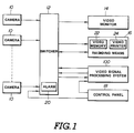
- the processing system 100 of Figure 2 is capable of being used in various applications, though it is disclosed hereinbelow in a case in which it is used in conjunction with a security monitor system, in accordance with a preferred embodiment of the invention, illustrated in Figure 1, for detecting changes in the condition of a predetermined monitored area.
- the security monitor system includes one or more cameras 10, each of which is focussed on a separate, predetermined monitored area to pick up separate video images of the corresponding monitored areas.
- the cameras 10 continuously output video signals, each of which contains data of the picked-up video image of the corresponding monitored area.
- the cameras 10 output their video signals to a switcher 12 which is connected to a video monitor 14 (such as a CRT video screen), a recording device 16 (such as a video memory 22 and a video printer 24), and the video signal processing system 100.
- a manually operable control panel 18 is connected to control the switcher 12 and the system 100.
- the switcher 12 continuously receives video signals from the cameras 10.
- the switcher 12 is programmed to select one of the video signals according to a predetermined schedule and feed the video signal to the monitor 14 which reproduces the video signal on a monitor screen as a visual image.
- a schedule for selecting video signals from various cameras can be preset in the switcher 12 for switching the connection between the camera and the monitor 14 at given intervals and in a given order.
- the switcher 12 can also be responsive to a camera selection command inputted through the control panel 18 to select a camera to be connected to the monitor 14 irrespective of the predetermined order.
- the interval for switching the cameras can be determined to be long enough for visual observation of the displayed picture for checking the condition of the monitored area, and short enough successfully to monitor various areas.
- the switcher 12 also selectively connects one of the cameras 10 at a time to the video signal processing system 100.
- the switcher 12 switches the connection between the cameras 10 and the video signal processing system 100 at predetermined intervals and in a given order.
- selection of the cameras to be connected to the system 100 is performed independently of selection of the cameras to be connected to the monitor 14.
- the switching interval for the connection between the cameras 10 and the system 100 is generally shorter than that for the connection between the cameras and the monitor 14.
- the switching timing for the connection between the cameras 10 and the video signal processing system 100 is determined according to the processing speed of the system 100. That is, the switching interval for the switching connection between the cameras 10 and the system 100 is set to be slightly longer than or equal to the maximum possible period for processing one field of a video signal.
- the video signal processing system 100 includes a binary video signal generator 118 ( Figure 2) which generally serves as an analog-to-digital converter for converting analog video signals from the cameras 10 supplied via the switcher 12 into binary digital video signals indicative of the video data.
- a threshold level is set in the binary video signal generator 118.
- the threshold level is manually adjustable via the control panel 18.
- the video signal processing system 100 compares the binary video signal with a reference signal which is indicative of reference video signal data. If the binary video signal matches the reference signal, it is determined that the video data is unchanged and thus that the condition of the corresponding monitored area is unchanged. If, however, the binary video signal does not match the reference signal, it is determined that a change in the video data has occurred and thus that a change in the condition of the corresponding monitored area has occurred.
- the video signal processing system 100 generates a signal indicative of a change in the video data, which signal is hereinafter referred to as a "change detection signal".
- This change detection signal is fed to an alarm generator 20 ( Figure 1) which is incorporated in the switcher 12.
- the alarm generator 20 which can comprise a bell, a buzzer, or a flashing light, for example, generates an alarm in response to the change detection signal.
- the alarm generator 20 is incorporated in the switcher 12, it is possible for the alarm generator to be a component independent of the security monitor system or to be an external component to be connected to the security monitor system.
- the switcher 12 is responsive to the change detection signal to produce an operation command for the recording device 16. Also, the switcher 12 supplies to the recording device 16 a video signal representative of the video data of the monitored area in which a change of video data has been detected. The recording device 16 is thus activated to record the video data inputted from the switcher 12. In the illustrated embodiment, the video memory 22 is then activated to record the video data fed from the switcher 12. Simultaneously, the video printer 24 becomes active to print a still image of the monitored area based on the video information recorded in the video memory 22.
- a VTR can be used as the recording device 16.
- the VTR will be activated in response to the operation command for performing the video data recording operation.
- the VTR may be maintained in operation for a given period of time so as to monitor the monitored area for the given period.
- FIG. 2 shows the construction of the video signal processing system 100 in more detail.
- the video signal processing system 100 is intended to be used in conjunction with a multi-channel security monitor system designed for monitoring a plurality of monitoring areas, the following discussion relates to single-channel video signal processing of a video signal from a single camera in order to simplify the disclosure and avoid confusion.
- the video signal processing system 100 comprises a digital circuit including a microprocessor 102.
- the microprocessor 102 is composed of a control processing unit (CPU) 104, a random access memory (RAM) 106 and a read only memory (ROM) 108.
- a coordinates comparator 110 is connected to the CPU 104 via a bus 112.
- a synchronisation signal separator 119 strips out synchronisation signals from the video signal.
- the synchronisation signal separator 119 is connected to a vertical synchronisation signal separator 114, a clock signal generator 116 and the coordinates comparator 110.
- the coordinates comparator 110 receives a vertical synchronisation signal Vsync from the vertical synchronisation signal separator 114 and a horizontal synchronisation signal Hsync from the synchronisation signal separator 119.
- the coordinates comparator 110 is also connected to the clock generator 116 to receive therefrom a clock signal having a given frequency, e.g. 4 MHz.
- the coordinates comparator 110 determines the address of the video data of each pixel on the basis of the vertical synchronisation signal Vsync, the horizontal synchronisation signal Hsync and the clock signal.
- the address given for the video data of each pixel identifies a memory block for storing the video data in a memory area RMEM of the RAM 106.
- the video data component of the analog video signal inputted from the switcher 12 is fed to the binary video signal generator 118, which converts the analog video signal into a corresponding binary digital video signal.
- the binary video signal outputted from the binary video signal generator 118 is in the form of serial data and is fed to a serial-to-parallel (S/P) converter 120 which converts it into parallel data which is fed to the CPU 104.
- S/P serial-to-parallel
- the address data representative of the address of the corresponding memory block is inputted to the CPU 104 from the coordinates comparator 110 via the bus 112. Therefore, the CPU 104 transfers the parallel data to a memory block identified by the address data.
- the video data of each pixel can be stored in the RMEM area of the RAM 106.
- the video data of the pixels residing in only a limited area is monitored.
- An example of the section monitored for a change in the video data is shown by a hatched area in Figure 3.
- the RMEM area of the RAM 106 is divided into 4-bite columns.
- the capacity of the S/P converter circuit 120 is set at 4 bites.
- the video data which has been series-to-parallel converted by the S/P converter circuit 120 is stored in the RMEM area of the RAM 106 in the order shown by arrows in Figure 4.
- the coordinates comparator 110 monitors the addresses of the pixels on the basis of the vertical synchronisation signal, the horizontal synchronisation signal and the clock signal for detecting the pixels on the horizontal scanning lines A1, A2 ... A n and in the predetermined section on the horizontal scanning lines.
- the CPU 104 supplies reference coordinate indicative signals representative of the coordinates of the pixels within the section of the field to be monitored. Such signals can be generated automatically from coordinate information inputted by an operator via the control panel 18.
- the coordinates comparator 110 compares the coordinate data derived with respect to each item of video data with reference coordinate indicative signal values to detect the video data of the pixels within the section to be monitored.
- the reference coordinate indicative signals contain coordinate data of the first pixel coordinates on respective horizontal scanning lines.
- the video data of a given number of pixels, which video data is inputted subsequently to the video data of the first pixel on the respective horizontal scanning lines A1, A2 ... A n is thus stored in the RMEM area of the RAM 106.
- the sections to be monitored for changes in video data will be set with respect to respective monitored areas. Since the video signals in the respective monitoring channels are not synchronised with each other, coordinate positions of the sections to be monitored have to be detected independently of the other channels.
- the data in the coordinates comparator 110 is reset in response to a channel switching control signal from the CPU 104. Then, the coordinates comparator 110 waits for the subsequently inputted vertical scanning line before starting to derive the coordinates for the respective pixels.
- FIG. 5 shows a detailed construction of the binary video signal generator 118 and the synchronisation signal separator 119.
- the binary video signal generator 118 and the synchronisation signal separator 119 comprise comparators 118a and 119a.
- the comparator 118a forming the binary video signal generator 118 has an inverting input terminal connected via an amplifier AMP to a video output terminal of the switcher 12.
- a non-inverting input terminal of the comparator 118a is connected to a reference voltage source via a variable resistor 118b.
- the resistance of the variable resistor 118b can be adjusted via the control panel 18.
- the reference voltage which serves as a threshold value V1 to be compared with the video signal level, varies. Therefore, by adjusting the resistance of the variable resistor 118b via the control panel 18, the threshold level V1 of the comparator 118a can be adjusted.
- the video signal processing system 100 monitors changes in luminance level for detecting changes in the condition of the monitored area. Therefore, the binary video signal is variable between a HIGH level "1" and a LOW level “0" depending upon the luminance level of the video signal.
- a HIGH level signal is outputted when the luminance level of the video signal is higher than the threshold level V1
- a LOW level is outputted when the luminance level of the video signal is lower than the threshold level V1. Therefore, the binary video signal indicates the luminance level at each pixel by a HIGH or a LOW level signal.
- the comparator 119a has an inverting input terminal connected to the video output terminal of the switcher 12, via the amplifier AMP, to receive therefrom the video signal.
- a non-inverting input terminal of the comparator 119a is connected to a reference signal value source Vo and to the anode of a diode 121 whose cathode is connected, via the amplifier AMP, to the output of the switcher 12.
- the comparator 119a compares inputs at its inverting and non-inverting input terminals for detecting synchronisation signals contained in the video signal.
- the comparator 119a outputs a HIGH level pulse signal when a synchronisation signal is detected in the video signal.
- the HIGH level pulse signal produced by the comparator 119a is hereinafter referred to as the "synchronisation pulse”.
- the synchronisation pulse output from the synchronisation signal separator 119 contains the vertical synchronisation signal and the horizontal synchronisation signal.
- the vertical synchronisation signal is further separated by the vertical synchronisation signal separator 114.
- Figure 9 is a flowchart showing the operation of deriving the reference signal.
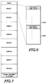
- Figure 7 shows the arrangement of the RAM 106, which comprises the memory area RMEM, other memory blocks, address or areas GMEM1, GMEM2 .... GMEMn, other memory and a stack.
- Figure 8 shows the arrangement of each memory block GMEM1, GMEM2 .... GMEMn in the RAM 106.
- the video data of the respective monitor channel and the reference signal data corresponding thereto are stored in these memory blocks. Therefore, if a single channel video signal is employed, a single memory block will be used for storing the video data.
- each memory block or address GMEM is composed of a first memory area 106a and a second memory area 106b.
- the first memory area 106a stores data for renewing the reference signal data. The manner of renewing the reference signal data will be described later.
- the second memory area 106b stores reference signal data in use.
- the data stored in the first memory area 106a includes an OR data component (hereinafter referred to as the "O1 signal”) and an AND data component (hereinafter referred to as the "A1 signal”).
- the reference signal data stored in the memory area 106b is composed of the O1 signal and an exclusive OR data component (hereinafter referred to as the "X1 signal").
- a pair of O1 and A1 signals stored in the memory area 106a constitutes data representative of the video data.
- a pair of O1 and X1 signals stored in the memory area 106b constitutes the reference data.
- the reference signal data is derived on the basis of the video data for several consecutive video signal fields, as set forth above. Therefore, the video data of a predetermined number n of video signal fields is sampled and stored in the memory area 106a in the form of pairs of O1 and A1 signals.
- the logical values (OR data and AND data) of the respective pixels are compared over the n fields of video data. This operation enables pixels whose logical values fluctuate to be detected.
- the reference data to be compared with the video data of the pixels for which fluctuation of the logical values are detected will not be derived so that the operation of comparing the video data and the reference data will never take place with regard to such pixels.
- a program for deriving the reference signal is executed at predetermined intervals by the CPU 104.
- the program is shown in flow chart form in Figure 9.
- initialisation is performed at a step 1000.
- the memory area 106a of a memory block GMEM is initialised.
- Initialisation of the memory area 106a is performed by setting all of the O1 signals to the level "0" and by setting all of the A1 signals to the level "1".
- the video data (V signal) of the first video signal field is read out. After this, the logical value of each pixel (i.e.
- the O1 signal is updated at a step 1004.
- the logical value of the pixel is compared with the A1 signal of the corresponding address of the memory area 106a and a logical AND operation is performed to derive AND data therebetween.
- the A1 signal in the corresponding address in the memory area 106a is updated.
- a counter (not shown) is incremented by 1.
- This counter value is compared, at a step 1008, with a given value n which corresponds to the number of video signal fields to be sampled.
- the process sequence returns to the step 1002 to repeat the processes of the steps 1002 to 1006 for the next video signal field. Therefore, the O1 signal and the A1 signal are updated n times.
- the counter value reaches the given value n, as determined at the step 1008, the process goes to a step 1010.
- a logical exclusive OR operation is performed on the O1 signal and the A1 signal to derive the exclusive OR data.
- the newly derived exclusive OR data is set as an X signal at a step 1010.
- the O1 signal (as updated in the step 1004) and the X signal (as derived in the step 1010) are stored, respectively, as an O2 signal and an X2 signal in the second memory area 106b of the GMEM memory block.
- the O2 signal and the X2 signal serve as the reference data for the corresponding pixel.
- all of the O1 signals in the first memory area 106a are set to "0" and all of the A1 signals in the first memory area 106b are set to "1", at a step 1013.
- the O1 signal which was updated n-times at the step 1004, will have a value of "0" only when the OR values derived n-times are all of value "0", as shown at (A) to (C) in Figure 10.
- the A1 signal will have a value of "1” only when all of the items AND data derived n-times at the step 1006 are of the value "1", as shown at (A), (B) and (D) in Figure 10.
- the X1 signal as derived in the step 1010 will have a value of "0" when the logical level of the video data over n-fields is held unchanged at the value "1" or the value "0", and will have a value of "1” when the logical value fluctuates among n fields of video data.
- the video data (V signal) of the subsequent field of the video signal is read out.
- the logical value of each pixel is compared with the X2 signal in the corresponding address of the second memory area 106b and a logical OR operation is performed to derive OR data therebetween, as shown at (A), (B), (C), (D), (E) and (G) in Figure 11.
- An exclusive OR logic operation is performed with respect to the derived OR data and the O2 signal to derive exclusive OR (XOR) data thereof at a step 1016, as shown at (E) and (F) in Figure 11.
- the XOR data derived with respect to each pixel is checked for finding out singular points in relation to the adjacent pixels, at a step 1018.
- a singular point is checked by comparing the XOR data derived in the step 1016 with the XOR data of the adjacent pixels.
- FIG.D when the video data is held unchanged, an XOR operation performed on the OR data and the O2 signal as derived in the step 1016 will produce "0" for all of the pixels.
- FIG.G), (H) and (I) in Figure 11 the XOR data will become "1" for a pixel whose video data changes.
- the XOR data obtained for all the pixels is checked to determine whether all of the items of XOR data have the value "0", which would indicate that no video data has changed. If all of the items of XOR data have the value "0", then the process goes to a step 1100.
- the logical value of the video signal is compared with the O1 signal to obtain OR data for updating the O1 signal with the obtained OR data.
- the logical value of the video signal is compared with the A1 signal to obtain AND data for updating the A1 signal with the obtained AND data.
- a counter (not shown) is incremented by "1".
- the counter value is compared with a given value m at a step 1104. If the counter value is smaller than m, the process goes back to the step 1014 to repeat the process through the steps 1014, 1016, 1018, 1020, 1100 and 1102. If the counter value is equal to m, the process goes to the step 1010.
- the process goes to a step 1022, in which a change detection signal is outputted. After outputting the change detection signal, the security monitor system is placed in a stand-by state for a given period of time. After expiry of the given stand-by period, the process returns to the step 1000 to resume security monitoring operations.
- the illustrated embodiment determines that the condition of the monitoring area has changed when a change of the video data in a least one pixel is detected, it would be possible slightly to reduce the sensitivity in order to avoid the influence of signal noise which can be superimposed on the video signal from the camera. This can be done by counting the number of pixels for which the video data is changed and comparing the counted value with a given threshold value. This technique is substantially the same as that discussed above in regard to the prior art. However, since the illustrated embodiment successfully avoids monitoring pixels for which the video data fluctuates, the threshold value to be used can be small enough to yield a satisfactorily high sensitivity.
Landscapes
- Engineering & Computer Science (AREA)
- Physics & Mathematics (AREA)
- General Physics & Mathematics (AREA)
- Multimedia (AREA)
- Signal Processing (AREA)
- Computer Vision & Pattern Recognition (AREA)
- Closed-Circuit Television Systems (AREA)
- Burglar Alarm Systems (AREA)
Claims (28)
- Procédé de traitement d'un signal vidéo pour détecter une modification dans les données vidéo contenues dans un signal vidéo généré par une source de signal vidéo, le procédé comprenant les étapes de :
conversion (118) d'un signal vidéo analogique reçu depuis la source de signal vidéo en un signal vidéo numérique en valeurs binaires correspondant contenant des valeurs logiques représentatives du niveau de signal des pixels respectifs ;
génération (102) d'un signal de référence numérique en échantillonnant un nombre prédéterminé (n) de trames de signal vidéo contenues dans le signal vidéo numérique, en soumettant à une comparaison le nombre prédéterminé de trames de signal vidéo échantillonnées et en excluant les pixels dont les données vidéo correspondantes fluctuent dans les trames de signal vidéo échantillonnées de telle sorte qu'une étape de comparaison entre une trame de signal vidéo et le signal de référence soit effectuée seulement pour les pixels dont les données vidéo sont maintenues constantes sur les trames échantillonnées et le signal de référence numérique est produit sur la base des données vidéo du nombre prédéterminé de trames de signal vidéo échantillonnées, ledit signal de référence contenant une composante de données (O2, X2) pour chaque pixel, laquelle composante de données est constituée par une composante de données OU (O2) des valeurs logiques correspondantes des trames de signal vidéo échantillonnées et par une composante de données OU-exclusif (X2) de la composante de données OU et par des composantes de données ET (A1) des valeurs logiques des trames de signal vidéo échantillonnées ; et
détection (102) d'une modification dans les données vidéo contenues dans le signal vidéo en comparant chaque trame de signal vidéo au signal de référence et en produisant un signal de détection de modification lorsqu'une modification dans les données vidéo est détectée. - Procédé selon la revendication 1, dans lequel l'étape de génération d'un signal de référence comprend en outre les étapes (1013) d'établissement de valeurs initiales pour les composantes de données OU (O1) et pour les composantes de données ET (A1) pour tous les pixels de telle sorte que la composante de données OU-exclusif dérivée (XOU) devienne une valeur prédéterminée lorsque les données vidéo de tous les pixels sont maintenues non modifiées.
- Procédé selon la revendication 1 ou 2, dans lequel l'étape de détection de modification comprend les étapes supplémentaires de réception (1014) du signal vidéo numérique et de réalisation d'une opération OU logique (1016) pour dériver une composante de données OU (O2) de la valeur logique et la composante de données OU-exclusif du signal de référence par rapport à chaque pixel et de réalisation d'une opération OU-exclusif logique pour dériver une composante de données OU-exclusif (XOU) des données OU dérivées et la composante de données OU du signal de référence, et de contrôle (1018) des données OU-exclusif (XOU) ainsi dérivées pour détecter une modification dans les données vidéo par rapport à chaque pixel afin de déterminer des points singuliers de modification.
- Procédé selon la revendication 3, dans lequel l'étape de détection comprend les étapes supplémentaires de comparaison (1020) des données OU-exclusif (XOU) dérivées de chaque pixel à la valeur prédéterminée pour détecter une modification des données vidéo et pour générer un signal de détection de modification.
- Procédé selon l'une quelconque des revendications précédentes, comprenant en outre l'étape de génération de signal vidéo source en détectant une caméra vidéo (10) en direction d'une zone de surveillance prédéterminée qui doit être surveillée, en captant une image vidéo de celle-ci et en générant un signal vidéo correspondant contenant des données vidéo ; et
en réponse au signal de détection de modification, génération d'une alarme (20) indicative d'une modification dans la condition de la zone de surveillance. - Procédé selon la revendication 5, dans lequel l'étape de génération de signal vidéo source comprend en outre des étapes d'orientation d'une pluralité de caméras (10) sur des zones de surveillance différentes pour capter des images vidéo séparées de celles-ci, et de commutation de connexions entre les caméras et le système de traitement de signal vidéo conformément à une règle prédéterminée.
- Procédé selon la revendication 6, comprenant en outre des étapes d'enregistrement du signal vidéo courant lors de la survenue du signal de détection de modification.
- Procédé selon la revendication 7, dans lequel l'étape d'enregistrement comprend l'impression d'une image vidéo de la zone de surveillance sur la base du signal vidéo courant lors de la survenue du signal de détection de modification.
- Procédé selon la revendication 7 ou 8, dans lequel l'étape d'enregistrement comprend l'enregistrement du signal vidéo courant pour une période temporelle donnée au moyen d'un enregistreur à bande vidéo en réponse au signal de détection de modification.
- Procédé selon l'une quelconque des revendications précédentes, comprenant en outre l'étape de reproduction du signal vidéo en vue d'une observation visuelle de la zone de surveillance.
- Procédé selon l'une quelconque des revendications précédentes, dans lequel l'étape de détection est limitée à la seule surveillance d'une modification dans les données vidéo pour les pixels contenus dans une section limitée d'une trame de signal vidéo.
- Procédé selon la revendication 11, dans lequel l'étape de génération de signal de référence comprend en outre la génération du signal de référence seulement par rapport à des données de référence des pixels contenus dans la section limitée.
- Procédé selon la revendication 12, dans lequel l'étape de génération de signal de référence comprend en outre le stockage de données vidéo des pixels contenus dans la section limitée dans un premier bloc mémoire numérique (RMEM) et le stockage du signal de référence dans un second bloc mémoire (GMEM).
- Procédé selon la revendication 12 ou 13, dans lequel l'étape de génération de signal de référence comprend en outre les étapes de séparation de signaux de synchronisation contenus dans le signal vidéo, de réception des signaux de synchronisation séparés et de détection de positions de pixels dans une trame de l'image vidéo et ainsi, les données vidéo correspondant aux pixels contenus dans la section limitée sont détectées et stockées dans le premier bloc mémoire (RMEM).
- Système de traitement de signal vidéo pour traiter un signal vidéo pour détecter une modification des données vidéo contenues dans un signal vidéo généré par une source de signal vidéo, le système comprenant :
un moyen de convertisseur (118) pour convertir un signal vidéo analogique reçu depuis la source de signal vidéo en un signal vidéo numérique en valeurs binaires correspondant contenant des valeurs logiques représentatives du niveau de signal des pixels respectifs ;
un moyen de générateur de signal de référence (102) pour générer un signal de référence numérique en échantillonnant un nombre prédéterminé (n) de trames de signal vidéo contenues dans le signal vidéo numérique, en comparant le nombre prédéterminé échantillonné de trames de signal vidéo et en excluant les pixels dont les données vidéo correspondantes fluctuent dans les trames de signal vidéo échantillonnées de telle sorte qu'une étape de comparaison entre un signal vidéo et le signal de référence soit effectuée seulement pour les pixels dont les données vidéo sont maintenues constantes sur les trames échantillonnées, en produisant le signal de référence numérique sur la base des données vidéo du nombre prédéterminé de trames de signal vidéo échantillonnées ; et
un moyen de détecteur (102) pour détecter une modification dans les données vidéo contenues dans le signal vidéo en comparant chaque trame de signal vidéo au signal de référence et en produisant un signal de détection de modification lorsqu'une modification dans le signal vidéo est détectée, caractérisé en ce que ledit moyen de génération génère un dit signal de référence contenant une composante de données (O2, X2) pour chaque pixel, laquelle composante de données est constituée par une composante de données OU (O2) de valeurs logiques correspondantes des trames de signal vidéo échantillonnées et par une composante de données OU-exclusif (X2) de la composante de données OU et par des composantes de données ET (A1) des valeurs logiques des trames de signal vidéo échantillonnées. - Système selon la revendication 15, dans lequel le moyen de générateur de signal de référence (102) fonctionne (1013) pour établir des valeurs initiales pour les composantes de données OU (O1) et pour les composantes de données ET (A1) pour tous les pixels de telle sorte que la composante de données OU-exclusif dérivée (XOU) devienne une valeur prédéterminée lorsque les données vidéo de tous les pixels sont maintenues non modifiées.
- Système selon la revendication 15 ou 16, dans lequel le moyen de détecteur (102) fonctionne (1014) pour recevoir le signal vidéo numérique, pour réaliser une opération OU logique afin de dériver une composante de données OU de la valeur logique et de la composante de données OU-exclusif (X2) du signal de référence par rapport à chaque pixel, pour réaliser une opération OU logique (1016) afin de dériver une composante de données OU-exclusif (XOU) des données OU dérivées et de la composante de données OU (O2) du signal de référence et pour contrôler (1018) les données OU-exclusif ainsi dérivées (XOU) pour détecter une modification dans les données vidéo par rapport à chaque pixel afin de déterminer des points singuliers de modification.
- Système selon la revendication 17, dans lequel le moyen de détecteur (102) fonctionne (1020) pour comparer les données OU-exclusif dérivées (XOU) de chaque pixel à la valeur prédéterminée pour détecter une modification dans les données vidéo.
- Système de surveillance de sécurité comprenant :
une caméra de signal vidéo (10) orientée en direction d'une zone prédéterminée qui doit être surveillée pour capter une image vidéo de cette zone et pour générer un signal vidéo correspondant contenant des données vidéo ;
un système de traitement de signal vidéo (100) selon l'une quelconque des revendications 15 à 18, agencé pour détecter une modification dans les données vidéo contenues dans le signal vidéo en provenance de la caméra de signal vidéo (10) ; et
une alarme (20) sensible à un signal de détection de modification produit par le moyen de détecteur (102) du système de traitement de signal vidéo (100) afin d'indiquer une modification dans la condition de la zone surveillée. - Système selon la revendication 19, comprenant une pluralité de caméras de signal vidéo (10) dirigées sur différentes zones prédéterminées qui doivent être surveillées pour capter des images vidéo séparées et un moyen de commutateur (12) pour commuter des connexions entre les caméras et le système de traitement de signal vidéo (100) conformément à une règle prédéterminée.
- Système selon l'une quelconque des revendications 15 à 20, lequel comprend un moyen d'enregistrement (16) qui fonctionne pour enregistrer le signal vidéo courant suite à la survenue du signal de détection de modification.
- Système selon la revendication 20, dans lequel le moyen d'enregistrement (16) comprend une imprimante vidéo (24) pour imprimer une image vidéo sur la base du signal vidéo courant suite à la survenue d'un signal de détection de modification.
- Système selon la revendication 21, dans lequel le moyen d'enregistrement (16) comprend un enregistreur à bande vidéo qui est sensible à un signal de détection de modification pour enregistrer le signal vidéo courant pendant une période temporelle donnée.
- Système selon l'une quelconque des revendications 15 à 23, lequel comprend un moniteur vidéo (14) pour reproduire le signal vidéo généré par la source de signal vidéo.
- Système selon l'une quelconque des revendications 15 à 24, lequel fonctionne pour surveiller une modification dans les données vidéo pour les pixels situés dans une section limitée (figure 3) d'une trame de signal vidéo.
- Système selon la revendication 25, lequel fonctionne de telle sorte que le signal de référence généré par le moyen de générateur de signal de référence (102) contienne seulement des données de référence des pixels situés dans la section limitée (figure 3).
- Système selon la revendication 26, lequel comprend une mémoire (106) comportant un premier bloc mémoire (RMEM) pour stocker les données vidéo des pixels contenus dans la section limitée (figure 3) et un second bloc mémoire (GMEM) pour stocker le signal de référence.
- Système selon la revendication 27, lequel inclut un séparateur de signal de synchronisation (119) pour séparer les signaux de synchronisation vis-à-vis du signal vidéo et un moyen de détection de coordonnées de pixel (110) pour recevoir les signaux de synchronisation séparés par le séparateur de signal de synchronisation (119) et pour détecter des positions de pixels dans une trame de l'image vidéo et ainsi, les données vidéo correspondant aux pixels contenus dans la section limitée (figure 3) sont détectées et stockées dans le premier bloc mémoire (RMEM) du moyen de mémoire (106).
Applications Claiming Priority (4)
| Application Number | Priority Date | Filing Date | Title |
|---|---|---|---|
| JP61222690A JP2565169B2 (ja) | 1986-09-20 | 1986-09-20 | 映像信号処理方法 |
| JP61222689A JPS6377284A (ja) | 1986-09-20 | 1986-09-20 | 映像信号処理装置 |
| JP222690/86 | 1986-09-20 | ||
| JP222689/86 | 1986-09-20 |
Publications (3)
| Publication Number | Publication Date |
|---|---|
| EP0261917A2 EP0261917A2 (fr) | 1988-03-30 |
| EP0261917A3 EP0261917A3 (en) | 1990-03-28 |
| EP0261917B1 true EP0261917B1 (fr) | 1994-03-02 |
Family
ID=26525015
Family Applications (1)
| Application Number | Title | Priority Date | Filing Date |
|---|---|---|---|
| EP87308347A Expired - Lifetime EP0261917B1 (fr) | 1986-09-20 | 1987-09-21 | Détection de changements dans des données vidéo |
Country Status (4)
| Country | Link |
|---|---|
| US (1) | US4774570A (fr) |
| EP (1) | EP0261917B1 (fr) |
| CA (1) | CA1278372C (fr) |
| DE (1) | DE3789183T2 (fr) |
Cited By (3)
| Publication number | Priority date | Publication date | Assignee | Title |
|---|---|---|---|---|
| WO2006002466A1 (fr) * | 2004-06-30 | 2006-01-12 | Vfs Technologies Limited | Appareil et procede de traitement d'images |
| USD939980S1 (en) | 2019-06-17 | 2022-01-04 | Guard, Inc. | Data and sensor system hub |
| US12198473B2 (en) | 2019-06-17 | 2025-01-14 | Guard, Inc. | Analysis and deep learning modeling of sensor-based object detection data in bounded aquatic environments |
Families Citing this family (63)
| Publication number | Priority date | Publication date | Assignee | Title |
|---|---|---|---|---|
| JPH01218181A (ja) * | 1988-02-25 | 1989-08-31 | Erubetsukusu Video Kk | 閉回路テレビジョン装置 |
| WO1991007850A1 (fr) * | 1989-11-09 | 1991-05-30 | Zone Technology Pty Limited | Camera video numerique |
| US5099322A (en) * | 1990-02-27 | 1992-03-24 | Texas Instruments Incorporated | Scene change detection system and method |
| US5034811A (en) * | 1990-04-04 | 1991-07-23 | Eastman Kodak Company | Video trigger in a solid state motion analysis system |
| JP2687670B2 (ja) * | 1990-04-19 | 1997-12-08 | 松下電器産業株式会社 | 動き検出回路および手ぶれ補正装置 |
| US5147297A (en) * | 1990-05-07 | 1992-09-15 | Alza Corporation | Iontophoretic delivery device |
| US5061997A (en) * | 1990-06-21 | 1991-10-29 | Rensselaer Polytechnic Institute | Control of visible conditions in a spatial environment |
| US5097328A (en) * | 1990-10-16 | 1992-03-17 | Boyette Robert B | Apparatus and a method for sensing events from a remote location |
| GB2249420B (en) * | 1990-10-31 | 1994-10-12 | Roke Manor Research | Improvements in or relating to intruder detection systems |
| WO1992010064A1 (fr) * | 1990-11-26 | 1992-06-11 | Eastman Kodak Company | Amelioration du signal video dans un systeme d'analyse de mouvement a semi-conducteurs |
| WO1992010065A1 (fr) * | 1990-11-26 | 1992-06-11 | Eastman Kodak Company | Circuit de declenchement de capteur telephotographique, monte dans un systeme d'analyse de mouvement a semi-conducteurs |
| WO1992010908A2 (fr) * | 1990-12-14 | 1992-06-25 | Battelle Memorial Institute | Systeme d'instrumentation video a vitesse rapide |
| US5321396A (en) * | 1991-02-07 | 1994-06-14 | Xerox Corporation | Indexing of audio/video data |
| GB2257598B (en) * | 1991-07-12 | 1994-11-30 | Hochiki Co | Surveillance monitor system using image processing |
| DE69229831T2 (de) * | 1991-09-12 | 2001-04-12 | Electronic Data Systems Corp., Plano | Bildanalysator |
| KR940007846B1 (ko) * | 1991-12-09 | 1994-08-25 | 주식회사 금성사 | 움직임 검출장치 |
| GB9206651D0 (en) * | 1992-03-26 | 1992-05-06 | Solid State Logic Ltd | Video processing |
| US6678461B1 (en) | 1992-04-10 | 2004-01-13 | Avid Technology, Inc. | Media recorder for capture and playback of live and prerecorded audio and/or video information |
| US5946445A (en) * | 1992-04-10 | 1999-08-31 | Avid Technology, Inc. | Media recorder for capture and playback of live and prerecorded audio and/or video information |
| JPH06153202A (ja) * | 1992-10-29 | 1994-05-31 | F M T:Kk | 異常監視装置 |
| FR2700046B1 (fr) * | 1992-12-30 | 1995-03-17 | Hymatom | Dispositif de transmission d'images d'un site protégé. |
| US6313872B1 (en) * | 1993-06-18 | 2001-11-06 | Isabelle R. Borg | Security system for homes and small offices |
| KR0128859B1 (ko) * | 1993-08-20 | 1998-04-10 | 배순훈 | 적응적인 영상부호화 제어장치 |
| GB2293716B (en) * | 1994-03-30 | 1998-10-07 | Sony Corp | Digital switcher |
| US7623754B1 (en) | 1995-02-23 | 2009-11-24 | Avid Technology, Inc. | Motion picture recording device using digital, computer-readable non-linear media |
| US6977673B1 (en) | 1995-02-23 | 2005-12-20 | Avid Technology, Inc. | Portable moving picture recording device including switching control for multiple data flow configurations |
| US5999406A (en) * | 1995-02-23 | 1999-12-07 | Avid Technology, Inc. | Dockable electronic equipment container |
| GB2299233A (en) * | 1995-03-21 | 1996-09-25 | Ibm | Video compression method involving conditional replenishment |
| US7532807B2 (en) * | 1995-04-07 | 2009-05-12 | Avid Technology, Inc. | Combined editing system and digital moving picture recording system |
| US5809200A (en) * | 1995-08-07 | 1998-09-15 | Victor Company Of Japan, Ltd. | Video signal recording apparatus |
| FR2741370B1 (fr) * | 1995-11-16 | 1998-05-29 | Poseidon | Systeme de surveillance d'une piscine pour la prevention des noyades |
| KR100213055B1 (ko) * | 1996-07-27 | 1999-08-02 | 윤종용 | 감시용 시스템에서의 기록 매체 절약형 기록방법 |
| US6031573A (en) * | 1996-10-31 | 2000-02-29 | Sensormatic Electronics Corporation | Intelligent video information management system performing multiple functions in parallel |
| EP1455516A3 (fr) * | 1996-10-31 | 2006-03-22 | Sensormatic Electronics Corporation | Système intelligent pour gérer des informations vidéo |
| GB2329294B (en) * | 1997-09-11 | 2002-01-16 | Hamlet Video Internat Ltd | Signal monitoring apparatus |
| US7005985B1 (en) | 1999-07-20 | 2006-02-28 | Axcess, Inc. | Radio frequency identification system and method |
| US6940998B2 (en) | 2000-02-04 | 2005-09-06 | Cernium, Inc. | System for automated screening of security cameras |
| DE20102477U1 (de) * | 2000-02-22 | 2001-05-03 | Wincor Nixdorf Gmbh & Co Kg | Einrichtung zum Schutz von SB-Automaten gegen Manipulationen |
| US7768546B1 (en) | 2000-05-12 | 2010-08-03 | Axcess International, Inc. | Integrated security system and method |
| US6801246B2 (en) | 2001-02-27 | 2004-10-05 | Thomson Licensing, S.A. | Method and apparatus for detecting change in video source material |
| CN1459193A (zh) * | 2001-03-09 | 2003-11-26 | 皇家菲利浦电子有限公司 | 图像切换装置中视频信号之间切换的方法 |
| US6792339B2 (en) * | 2002-02-19 | 2004-09-14 | International Business Machines Corporation | Artificial passenger with condition sensors |
| US6786730B2 (en) | 2002-03-01 | 2004-09-07 | Accelerized Golf Llc | Ergonomic motion and athletic activity monitoring and training system and method |
| AU2003203110B2 (en) | 2002-08-08 | 2009-07-16 | Claire-Lise Boujon | Rescue and security device for swimming pools and amusement parks |
| CA2472871C (fr) * | 2004-02-18 | 2011-10-25 | Inter-Cite Video Inc. | Systeme et methode de diagnostic automatise a distance du fonctionnement d'un reseau d'enregistrement video numerique |
| US7841120B2 (en) | 2004-03-22 | 2010-11-30 | Wilcox Industries Corp. | Hand grip apparatus for firearm |
| KR20070008601A (ko) * | 2004-03-24 | 2007-01-17 | 세르늄 코포레이션 | 영역에 의한 세그먼트화 이득을 이용한 비디오 분석의 개선 |
| US8295541B2 (en) | 2004-06-30 | 2012-10-23 | Vision Fire & Security Pty Ltd | System and method for detecting a change in an object scene |
| WO2006118563A1 (fr) | 2005-04-29 | 2006-11-09 | Chubb International Holdings Limited | Procede et dispositif de localisation constante de region d'interet |
| US7822224B2 (en) | 2005-06-22 | 2010-10-26 | Cernium Corporation | Terrain map summary elements |
| US7504965B1 (en) | 2005-08-05 | 2009-03-17 | Elsag North America, Llc | Portable covert license plate reader |
| US8290225B2 (en) * | 2005-12-14 | 2012-10-16 | Koninklijke Philips Electronics N.V. | Method and device for relating medical 3D data image viewing planes to each other |
| US7800503B2 (en) | 2006-05-11 | 2010-09-21 | Axcess International Inc. | Radio frequency identification (RFID) tag antenna design |
| US8619136B2 (en) * | 2006-12-01 | 2013-12-31 | Centurylink Intellectual Property Llc | System and method for home monitoring using a set top box |
| TW200929071A (en) * | 2007-12-25 | 2009-07-01 | Altek Corp | Image processing method and image capture apparatusapplying the same |
| US8687626B2 (en) * | 2008-03-07 | 2014-04-01 | CenturyLink Intellectual Property, LLC | System and method for remote home monitoring utilizing a VoIP phone |
| US8638194B2 (en) | 2008-07-25 | 2014-01-28 | Axcess International, Inc. | Multiple radio frequency identification (RFID) tag wireless wide area network (WWAN) protocol |
| US9123227B2 (en) * | 2008-10-13 | 2015-09-01 | The Boeing Company | System for checking security of video surveillance of an area |
| US8571261B2 (en) | 2009-04-22 | 2013-10-29 | Checkvideo Llc | System and method for motion detection in a surveillance video |
| US20100296742A1 (en) * | 2009-05-22 | 2010-11-25 | Honeywell Inernational Inc. | System and method for object based post event forensics in video surveillance systems |
| US9256803B2 (en) | 2012-09-14 | 2016-02-09 | Palo Alto Research Center Incorporated | Automatic detection of persistent changes in naturally varying scenes |
| US9659237B2 (en) | 2012-10-05 | 2017-05-23 | Micro Usa, Inc. | Imaging through aerosol obscurants |
| US10643665B2 (en) * | 2015-04-29 | 2020-05-05 | Tomtom International B.V. | Data processing systems |
Family Cites Families (9)
| Publication number | Priority date | Publication date | Assignee | Title |
|---|---|---|---|---|
| FR2372425A1 (fr) * | 1976-11-26 | 1978-06-23 | Solvay | Procede et dispositif pour controler la nature corrosive, erosive et/ou incrustante d'un liquide |
| DE2710883C2 (de) * | 1977-03-12 | 1979-04-12 | Robert Bosch Gmbh, 7000 Stuttgart | System zur Diskrimination eines Videosignals |
| DE2715083C3 (de) * | 1977-04-04 | 1983-02-24 | Robert Bosch Gmbh, 7000 Stuttgart | System zur Diskrimination eines Videosignals |
| US4257063A (en) * | 1979-03-23 | 1981-03-17 | Ham Industries, Inc. | Video monitoring system and method |
| US4337481A (en) * | 1980-06-10 | 1982-06-29 | Peter Mick | Motion and intrusion detecting system |
| JPS6360960B2 (fr) * | 1980-10-22 | 1988-11-25 | ||
| GB2150724A (en) * | 1983-11-02 | 1985-07-03 | Christopher Hall | Surveillance system |
| US4630110A (en) * | 1984-02-15 | 1986-12-16 | Supervision Control Systems, Inc. | Surveillance system |
| US4679077A (en) * | 1984-11-10 | 1987-07-07 | Matsushita Electric Works, Ltd. | Visual Image sensor system |
-
1987
- 1987-09-16 US US07/097,496 patent/US4774570A/en not_active Expired - Lifetime
- 1987-09-17 CA CA000547152A patent/CA1278372C/fr not_active Expired - Lifetime
- 1987-09-21 EP EP87308347A patent/EP0261917B1/fr not_active Expired - Lifetime
- 1987-09-21 DE DE3789183T patent/DE3789183T2/de not_active Expired - Fee Related
Cited By (4)
| Publication number | Priority date | Publication date | Assignee | Title |
|---|---|---|---|---|
| WO2006002466A1 (fr) * | 2004-06-30 | 2006-01-12 | Vfs Technologies Limited | Appareil et procede de traitement d'images |
| USD939980S1 (en) | 2019-06-17 | 2022-01-04 | Guard, Inc. | Data and sensor system hub |
| USD957966S1 (en) | 2019-06-17 | 2022-07-19 | Guard, Inc. | Tile sensor unit |
| US12198473B2 (en) | 2019-06-17 | 2025-01-14 | Guard, Inc. | Analysis and deep learning modeling of sensor-based object detection data in bounded aquatic environments |
Also Published As
| Publication number | Publication date |
|---|---|
| DE3789183D1 (de) | 1994-04-07 |
| EP0261917A3 (en) | 1990-03-28 |
| EP0261917A2 (fr) | 1988-03-30 |
| DE3789183T2 (de) | 1994-06-23 |
| US4774570A (en) | 1988-09-27 |
| CA1278372C (fr) | 1990-12-27 |
Similar Documents
| Publication | Publication Date | Title |
|---|---|---|
| EP0261917B1 (fr) | Détection de changements dans des données vidéo | |
| US5059796A (en) | Infrared monitoring system | |
| US7286709B2 (en) | Apparatus and computer program for detecting motion in image frame | |
| US8437504B2 (en) | Imaging system and imaging method | |
| AU2001278180A1 (en) | A method of searching recorded digital video for areas of activity | |
| US3781468A (en) | Television surveillance system | |
| US20080049103A1 (en) | Information recording/reproducing apparatus | |
| US4963968A (en) | Method and apparatus for validating teletext data | |
| JP2565169B2 (ja) | 映像信号処理方法 | |
| KR0138137B1 (ko) | 감시용 카메라 시스템 | |
| WO1988000784A1 (fr) | Appareil detecteur de mouvements sensible aux informations portant sur les bords d'objets contenues dans des signaux de television | |
| JPH057363A (ja) | 画像監視装置 | |
| KR200238157Y1 (ko) | 폐쇄회로 텔레비전 시스템의 사건 발생내역 기록 장치 | |
| JP3185402B2 (ja) | 画像処理侵入者検知装置 | |
| US4750210A (en) | Method and apparatus for finding objects within a visual display | |
| JPH06153155A (ja) | 動画像の拾い見装置 | |
| JPH08265736A (ja) | Cctv監視システム | |
| JPH05300440A (ja) | 固体撮像装置 | |
| JP3043457B2 (ja) | 監視装置 | |
| JP3423246B2 (ja) | 監視装置 | |
| JPH08317312A (ja) | 字幕検出装置 | |
| JPS6377284A (ja) | 映像信号処理装置 | |
| JP2000069457A (ja) | カメラ監視システム | |
| JPH043599A (ja) | ビデオテープレコーダの画像評価装置 | |
| JPH11283133A (ja) | 監視装置 |
Legal Events
| Date | Code | Title | Description |
|---|---|---|---|
| PUAI | Public reference made under article 153(3) epc to a published international application that has entered the european phase |
Free format text: ORIGINAL CODE: 0009012 |
|
| AK | Designated contracting states |
Kind code of ref document: A2 Designated state(s): DE FR GB NL |
|
| PUAL | Search report despatched |
Free format text: ORIGINAL CODE: 0009013 |
|
| AK | Designated contracting states |
Kind code of ref document: A3 Designated state(s): DE FR GB NL |
|
| 17P | Request for examination filed |
Effective date: 19900822 |
|
| 17Q | First examination report despatched |
Effective date: 19920605 |
|
| GRAA | (expected) grant |
Free format text: ORIGINAL CODE: 0009210 |
|
| AK | Designated contracting states |
Kind code of ref document: B1 Designated state(s): DE FR GB NL |
|
| REF | Corresponds to: |
Ref document number: 3789183 Country of ref document: DE Date of ref document: 19940407 |
|
| ET | Fr: translation filed | ||
| PLBE | No opposition filed within time limit |
Free format text: ORIGINAL CODE: 0009261 |
|
| STAA | Information on the status of an ep patent application or granted ep patent |
Free format text: STATUS: NO OPPOSITION FILED WITHIN TIME LIMIT |
|
| 26N | No opposition filed | ||
| REG | Reference to a national code |
Ref country code: GB Ref legal event code: IF02 |
|
| PGFP | Annual fee paid to national office [announced via postgrant information from national office to epo] |
Ref country code: FR Payment date: 20050823 Year of fee payment: 19 |
|
| PGFP | Annual fee paid to national office [announced via postgrant information from national office to epo] |
Ref country code: NL Payment date: 20050904 Year of fee payment: 19 |
|
| PGFP | Annual fee paid to national office [announced via postgrant information from national office to epo] |
Ref country code: DE Payment date: 20050915 Year of fee payment: 19 |
|
| PGFP | Annual fee paid to national office [announced via postgrant information from national office to epo] |
Ref country code: GB Payment date: 20050921 Year of fee payment: 19 |
|
| PG25 | Lapsed in a contracting state [announced via postgrant information from national office to epo] |
Ref country code: NL Free format text: LAPSE BECAUSE OF NON-PAYMENT OF DUE FEES Effective date: 20070401 |
|
| PG25 | Lapsed in a contracting state [announced via postgrant information from national office to epo] |
Ref country code: DE Free format text: LAPSE BECAUSE OF NON-PAYMENT OF DUE FEES Effective date: 20070403 |
|
| GBPC | Gb: european patent ceased through non-payment of renewal fee |
Effective date: 20060921 |
|
| NLV4 | Nl: lapsed or anulled due to non-payment of the annual fee |
Effective date: 20070401 |
|
| REG | Reference to a national code |
Ref country code: FR Ref legal event code: ST Effective date: 20070531 |
|
| PG25 | Lapsed in a contracting state [announced via postgrant information from national office to epo] |
Ref country code: GB Free format text: LAPSE BECAUSE OF NON-PAYMENT OF DUE FEES Effective date: 20060921 |
|
| PG25 | Lapsed in a contracting state [announced via postgrant information from national office to epo] |
Ref country code: FR Free format text: LAPSE BECAUSE OF NON-PAYMENT OF DUE FEES Effective date: 20061002 |