EP0261945A1 - Hydraulische Spannvorrichtung mit Schwenkbarem Spannarm - Google Patents
Hydraulische Spannvorrichtung mit Schwenkbarem Spannarm Download PDFInfo
- Publication number
- EP0261945A1 EP0261945A1 EP87308405A EP87308405A EP0261945A1 EP 0261945 A1 EP0261945 A1 EP 0261945A1 EP 87308405 A EP87308405 A EP 87308405A EP 87308405 A EP87308405 A EP 87308405A EP 0261945 A1 EP0261945 A1 EP 0261945A1
- Authority
- EP
- European Patent Office
- Prior art keywords
- clamp
- hydraulic
- spring
- clamp arm
- piston rod
- Prior art date
- Legal status (The legal status is an assumption and is not a legal conclusion. Google has not performed a legal analysis and makes no representation as to the accuracy of the status listed.)
- Granted
Links
Images


Classifications
-
- B—PERFORMING OPERATIONS; TRANSPORTING
- B25—HAND TOOLS; PORTABLE POWER-DRIVEN TOOLS; MANIPULATORS
- B25B—TOOLS OR BENCH DEVICES NOT OTHERWISE PROVIDED FOR, FOR FASTENING, CONNECTING, DISENGAGING, OR HOLDING
- B25B5/00—Clamps
- B25B5/06—Arrangements for positively actuating jaws
- B25B5/061—Arrangements for positively actuating jaws with fluid drive
- B25B5/064—Arrangements for positively actuating jaws with fluid drive with clamping means pivoting around an axis perpendicular to the pressing direction
-
- B—PERFORMING OPERATIONS; TRANSPORTING
- B25—HAND TOOLS; PORTABLE POWER-DRIVEN TOOLS; MANIPULATORS
- B25B—TOOLS OR BENCH DEVICES NOT OTHERWISE PROVIDED FOR, FOR FASTENING, CONNECTING, DISENGAGING, OR HOLDING
- B25B5/00—Clamps
- B25B5/06—Arrangements for positively actuating jaws
- B25B5/061—Arrangements for positively actuating jaws with fluid drive
Definitions
- the present invention relates to a hydraulic clamp for securing a workpiece to a work-holding plate such as the table or work-pallet of a machining centre. More particularly it relates to a hydraulic clamp consisting of a clamp arm and a hydraulic cylinder arranged in a clamp housing one before the other longitudinally so that the clamp arm is swung longitudinally by the hydraulic cylinder.
- FIG. ll shows a construction l described in Japanese laid-open utility model application No. l9l227/'84
- FIG. l2 and l3 show another known construction 2 the present inventor is aware of. Parts and members of the constructions 1 and 2 having like functions are referred to by the same numerals in the drawings.
- a hydraulic clamp 202 comprises a clamp arm 204 and a hydraulic cylinder 205 arranged one before the other longitudinally in a clamp housing 203, the clamp arm 204 is pivotally held by a fulcrum shaft 209 extending from both walls 207, 207 of the clamp housing 203 to be freely swingable longitudinally.
- An elastic body 257 serves to push back the clamp arm 204 to be inward of the front face of the clamp housing 203, while it is driven outward of the front face of the same when a piston 2l4 of the hydraulic cylinder 205 is driven forward.
- the clamp housing 203 has its front and rear ends secured to a work pallet 20l by means of bolts 237, the clamp arm 204 is swung forward by hydraulically driving forward the piston 2l4 of the hydraulic cylinder 205, a workpiece W (or die) is pressed by the clamp arm 204 against a work holder 20la (as shown in the figure by two-dot chain line) and the workpiece W, thus clamped, is worked on or work using a die is carried out.
- the clamp arm 204 is swung back by the elastic body 257 into the clamp housing 203 automatically as the piston l4 is retracted.
- a spring room 26l is formed below the hydraulic cylinder 205, an elastic body 257 consisting of a compressive coil spring is housed therein and the springy force of the elastic body 257 is transmitted to the clamp arm 204 via a link mechanism 262.
- the height of the clamp housing 203 is increased by that of the spring room 26l making the hydraulic clamp bulky and, worse, the required link mechanism causes an increase of the number of the constituent parts thereby making the construction of the hydraulic clamp 202 more complicated.
- the elastic body for pushing back the clamp arm 204 is formed as follows.
- the elastic body 257 consists of a torsion coil spring, a through recess 258 is provided near the lower end of the clamp arm 204 for housing the spring which extends axially with respect to a fulcrum shaft 209.
- the fulcrum shaft 209 has set thereon the elastic body 257 consisting of the torsion coil spring with one end thereof held by the clamp housing 203 and the other end there of connected with the through recess 258.
- a hydraulic clamp comprising a clamp arm and a hydraulic cylinder arranged one before the other longitudinally in a clamp housing, the clamp arm being pivotally mounted on the clamp housing to be swingable longitudinally, and being driven forwardly same when a piston of said hydraulic cylinder is driven forward, an elastic body being provided for pushing back the clamp arm, characterised in that the elastic body extends from an intermediate position along the clamp arm to a part of the hydraulic cylinder.
- the present invention at least in its preferred form is intended to accomplishing the following objects with simultaneous miniaturization and simplification of its construction.
- An object of the present invention is to ensure against dust outside getting into the clamp housing to cause malfunction of the clamp arm, hydraulic cylinder and the like.
- Another object of the present invention is to enable powerfully pushing back the clamp arm by means of a elastic body.
- a still another object of the present invention is to minimize the size the diameter of the fulcrum shaft of the clamp arm.
- the present invention in its preferred form relates to the following construction of an hydraulic clamp.
- a hydraulic clamp with a swinging clamp arm wherein inside a clamp housing a clamp arm and a hydraulic cylinder are arranged one before the other longitudinally, the clamp arm is pivotally supported near its lower end by a fulcrum shaft connecting both sides walls of the clamp housing to swing freely in the longitudinal direction, an elastic body is provided to push back the clamp arm to be inward of the front face of the clamp housing and the clamp arm is driven to be swung forward to be beyond the front face of the clamp housing as the piston of the hydraulic cylinder is moved forward, the aforesaid elastic body is provided to extend from middle in height of the clamp arm to a constituent member of the hydraulic cylinder located behind thereof.
- constituent members of the hydraulic cylinder are known, among others, fixed members such as bottom and peripheral wall and movable members such as piston rod.
- This invention which relates to the aforesaid construction, has the following effects or features.
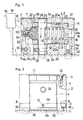
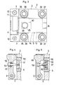
- FIGS. l to l0 show embodiments of the present invention, while FIGS. ll through l3 show prior art constructions.
- FIGS. l to 3 show the first embodiment , of which FIG. l is a longitudinal side sectional view, FIG. 2 is a front elevation and FIG. 3 is a plan view.
- reference numeral l is a work pallet, and a work W is fixed to a work holding jig la of this work pallet l by means of a hydraulic clamp 2.
- This hydraulic clamp 2 comprises a clamp housing 3 which is fixedly attached to the work pallet l and in the front portion of the clamp housing 3 is provided a claw-shaped clamp arm 4 and in the rear portion thereof is provided a hydraulic cylinder 5 for driving the clamp arm 4.
- the solid line shows the arrangement in unclamped condition and the two-dot chain line shows that in clamped condition.
- the left and right walls 7, 7 of the clamp housing 3 extend forwardly and near their lower edge there are formed fulcrum holes 8, 8 with their cenres aligned.
- the clamp arm 4 is placed between the extended side walls 7, 7 and a fulcrum shaft 9 is set through both fulcrum holes 8, 8 and another formed near the lower end of the clamp arm 4 in betwee n.
- the clamp arm 4 is fixedly secured by means of a setscrew l0 and thereby this clamp arm 4 is made freely swingable longitudinally and pivotally supported in the fulcrum holes 8, 8.
- scraper ll in contact with the top end of the aforesaid clamp arm 4 as it swings.
- This scraper ll is set between the left and right walls 7, 7 and both ends of the scraper ll are fixedly secured to both side walls 7, 7 by means of countersunk screws.
- a scraper projecting therefrom Near the lower end of the clamp arm 4 there is provided a scraper projecting therefrom, and this scraper 4b can be brought into contact with the work pallet l.
- This hydraulic cylinder 5 is of the spring-return single acting type.
- a cylinder chamber l3 extending longitudinally, and into this cylinder chamber l3 a piston l4 is inserted oiltight and freely slidable. Behind this piston a drive chamber l5 is provided.
- Reference numeral l6 is a oil supply-discharge port and l6a is a spare port. Also provided is a return spring l8 which urges the aforesaid piston l4 rearward.
- a cylindrical piston rod 20 projects forwardly from the aforesaid piston l4 and an output part 2l at the forward end of this piston rod 20 comes into contact with the back of the clamp arm 4 at the point of application of force.
- the aforesaid return spring l8 is inserted into the cylindrical hole 23 of the piston rod 20.
- This return spring l8 consists of a compression coil spring and its rear end is held by the rear end 23a of the cylindrical hole 23 and, at the same time, the front end is held by the clamp housing 3 via a spring holding pin 25.
- a pair of aligned pin holding holes 28, 28 are provided in the top 3a and bottom 3b of the clamp housing 3 near the front end of the clamp housing 3, the piston rod 20 and the cylindrical hole 23 of the piston rod 23.
- the spring holding pin 25 is set between the aforesaid pin-holding holes 28, 28 to be held at both ends.
- the lower end of this spring holding pin 25 is secured to the clamp housing 3 with a setscrew 29.
- On the rear side of the middle portion of the vertically set spring holding pin 25 is formed a slot or recess 26 for holding the forward end of the return spring l8.
- the piston rod 20 has a pair of longitudinally extending slots 30, 30 formed in it to allow movement of the piston rod without interference with the spring holding pin 25. Both anti-interference slots 30, 30 are so formed to allow the pin 25 to pass through the upper peripheral wall section 20a and lower peripheral wall section 20b of the piston rod.
- an elastic body is provided for pushing back the clamp arm 4 to be inward of the front face.
- This elastic body here consists of cone-shaped tension coil spring 32 and is provided to extend from the middle portion in height of the clamp arm 4 to some constituent member of the hydraulic cylinder 5 located behind the clamp arm 4. That is, a nut 34 is screwed down on a bolt 33 to be secured to the middle portion in height of clamp arm 4, and to this nut 34 the front end of the coil of the tension coil spring 32 is connected by screwing .
- the rear end of the coil of the tension coil spring 32 is connected by screwing with the front end of cylindrical hole 23 of the piston rod 20 as a movable member of the hydraulic cylinder 5.
- the hydraulic clamp 2 of the above-described construction is fix edly secured to the work pallet by the use of a pair each of fastening bolts 36, 37 for the front and rear portions thereof.
- a vertical pair of holes 38, 38 for fastening bolts are provided on both sides equidistant from the spring holding pin 25.
- a vertical pair of holes 39, 39 for fastening bolts are provided on both sides.
- Fastening bolts 36, 37 are set through the aforesaid bolt holes 38, 39 respectively.
- the front fastening bolt holes 38 are safe from interference with the pin-holding holes 28 for the spring holding pins 25, it is possible to distribute the bolt holes 38 nearer to the front edge of the clamp housing 3. This means an increased arm length for the moment of fastening force F for the fastening bolts 36 in the front row with respect to the rear edge 40 of the clamp housing as the fulcrum for inversion, hence the hydraulic clamp 2 is strongly fixed to the work pallet.
- the aforesaid pin-holding holes 28 for the spring holding pins 25 are provided as through holes in the same direction with the holes 38, 39 for the fastening bolts, it is possible to drill these two types of holes 38, 39 as well as the pin holding holes 28, 28 from the same side as the holes to be made in the clamp housing 3. Hence, the number of working steps can be decreased and less effort is required for manufacturing the hydraulic clamp 2.
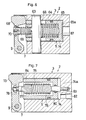
- FIG. 4 to 7 there are shown other embodiments and explained below are their differences from the first embodiment described above.
- FIG. 4 is given to show the second embodiment of the present invention.
- the elastic body consists of an elastic member 49 such as rubber.
- a nut member 5l is screwed tightly in the front end of a piston rod 50 of the hydraulic cylinder 5.
- a bolt 53 passes longitudinally through a clamp arm and is screwed into the nut member 5l.
- an elastic member 49 consisting of annular molded piece of rubber.
- FIG. 5 shows the third embodiment of the present invention, which, compared with the above FIG. 4, is modified as follows.
- a cylindrical stop member 56 is fixed in the front end of a piston rod 55 of the hydraulic cylinder 5 by screwing.
- This stop member 56 with its cylindrical hole has a nut member 57 connected therewith by screwing from behind.
- a bolt 59 passes longitudinally through a clamp arm 58 and is screwed into the nut member 57.
- an elastic member 60 consisting of rubber molded in an annular form.
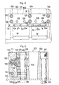
- FIG. 6 shows the fourth embodiment of the present invention.
- a spring holding pin 63 is arranged to be upright and a holding jig 66 for the return spring is fixed to the spring holding pin 63 inside the cylindrical hole 65 of the piston rod 64 of the hydraulic cylinder 5.
- a return spring 67 is a square-sectioned compression spring.
- An elastic body consisting of a tension coil spring 69 extend from the middle in height of a clamp arm 68 to the holding jig 66 for the return spring which is a fixed member of the hydraulic cylinder 5.
- a spring mount 70 is fixedly attached to the middle point in height of the clamp arm 68. The front end of the tension coil spring 69 is screwed to the spring mount 70 and the rear end of the tension coil spring 69 is screwed to the front end of the holding jig 66 for the return spring.
- FIG. 7 shows the fifth embodiment of the present invention.
- an elastic body consisting of a tension spring 75 extends from the middle in height of a clamp arm 73 to the bottom wall 74a of a cylinder chamber 74 which is a fixed member of the hydraulic cylinder 5.
- the front end of a front spring mount 77 is fixed to the middle point in height of the clamp arm by means of a nut 78 and the rear end of a rear spring mount 79 is fixed to the bottom wall 74 of the cylinder chamber 74.
- This rear spring mount 79 is so arranged that its longitudinally centre portion passes through a hole in a piston 80 and make with the piston 80 an oiltight and freely slidable seal.
- the front end of the tension coil spring 75 is screwed to a front spring mount 77 and simultaneously the rear end of the aforesaid tension coil spring 75 is screwed to the rear spring mount 79.
- FIGS. 8 to l0 show the sixth embodiment which uses a multiplicity of hydraulic clamps.
- a work pallet l0l is provided with a multiplicity of hydraulic clamps l02 so that a multiplicity of workpieces can be clamped simultaneously.
- a clamp housing l03 is constructed using long square bars and has front and rear vertical through bolt holes l38, l39 for fixing by bolting. Front fastening bolts l36 are set through the front bolt holes l38 and rear fastening bolts l37 set through the rear bolt holes l39.
- the work pallet l0l has formed therein inverse T-sectioned grooves l34 in which a plurality of nuts l35 and a plurality of front and rear fastening bolts l36, l37 are set for fixing the clamp housing l03.
- a plurality of clamp arms l04 and hydraulic cylinders l05 are provided properly spaced in the longitudinal direction (transverse direction in FIG. 8 AND l0) a plurality of clamp arms l04 and hydraulic cylinders l05.
- each clamp arm supporting frame l07 separates from the clamp housing l03, and each clamp arm supporting frame l07 is secured to the front portion of the clamp housing l03 by the use of fastening bolts 143.
- a fulcrum hole l08 Near the lower end of each supporting frame l07 is a fulcrum hole l08 and a fulcrum shaft l09 is set through a supporting hole l04a of each clamp arm l04 and the fulcrum holes 108, 108 on both sides thereof.
- Each fulcrum shaft 109 is secured to the clamp arm 104 by means of setscrews 110.
- a scraper 111 makes contact with the swingable top of each clamp arm 104.
- the scraper is long and is secured to the top of each clamping arm supporting frame 107 by countersunk screws. Between the middle portion in height of the clamp arm 104 and a piston rod 120 is an elastic body consisting of a tension coil spring 132 by the use of bolts 133.
- Pin supporting holes 128 of spring holding pins 125 are arranged to pass through the clamp housing 103 in the same way as described above in the embodiment 1.
Landscapes
- Engineering & Computer Science (AREA)
- Mechanical Engineering (AREA)
- Jigs For Machine Tools (AREA)
Applications Claiming Priority (4)
| Application Number | Priority Date | Filing Date | Title |
|---|---|---|---|
| JP14524686U JPH0226589Y2 (de) | 1986-09-22 | 1986-09-22 | |
| JP145247/86U | 1986-09-22 | ||
| JP145246/86U | 1986-09-22 | ||
| JP14524786U JPH0226590Y2 (de) | 1986-09-22 | 1986-09-22 |
Related Child Applications (1)
| Application Number | Title | Priority Date | Filing Date |
|---|---|---|---|
| EP90122053.3 Division-Into | 1987-09-22 |
Publications (2)
| Publication Number | Publication Date |
|---|---|
| EP0261945A1 true EP0261945A1 (de) | 1988-03-30 |
| EP0261945B1 EP0261945B1 (de) | 1992-04-01 |
Family
ID=26476418
Family Applications (2)
| Application Number | Title | Priority Date | Filing Date |
|---|---|---|---|
| EP87308405A Expired EP0261945B1 (de) | 1986-09-22 | 1987-09-22 | Hydraulische Spannvorrichtung mit Schwenkbarem Spannarm |
| EP90122053A Expired - Lifetime EP0422691B1 (de) | 1986-09-22 | 1987-09-22 | Hydraulische Spannvorrichtung mit schwenkbarem Spannarm |
Family Applications After (1)
| Application Number | Title | Priority Date | Filing Date |
|---|---|---|---|
| EP90122053A Expired - Lifetime EP0422691B1 (de) | 1986-09-22 | 1987-09-22 | Hydraulische Spannvorrichtung mit schwenkbarem Spannarm |
Country Status (3)
| Country | Link |
|---|---|
| US (1) | US4830349A (de) |
| EP (2) | EP0261945B1 (de) |
| DE (2) | DE3785679T2 (de) |
Cited By (2)
| Publication number | Priority date | Publication date | Assignee | Title |
|---|---|---|---|---|
| CN109894895A (zh) * | 2019-03-08 | 2019-06-18 | 天津大学 | 一种基于液压的增力夹紧机构 |
| CN116493967A (zh) * | 2023-04-04 | 2023-07-28 | 湖南生物机电职业技术学院 | 一种数控机床用快速夹紧的机床夹具 |
Families Citing this family (12)
| Publication number | Priority date | Publication date | Assignee | Title |
|---|---|---|---|---|
| JPH03178744A (ja) * | 1989-12-07 | 1991-08-02 | Kosumetsuku:Kk | クランプ具傾斜直動形油圧クランプ |
| US5115110A (en) * | 1990-06-18 | 1992-05-19 | Delaware Capital Formation, Inc. | Hydraulic quick change clamp |
| BR9202708A (pt) * | 1992-07-16 | 1994-01-18 | Luciano Trindade De Sousa Mont | Prendedor mecanico com travamento por cunha |
| AT403353B (de) * | 1992-10-28 | 1998-01-26 | Peter Khu & Co | Spannplatte |
| JPH07132431A (ja) * | 1993-11-05 | 1995-05-23 | Kosumetsuku:Kk | ネジ式クランプ装置 |
| JP3569069B2 (ja) * | 1996-04-23 | 2004-09-22 | 株式会社コスメック | クランプ装置 |
| JP3968444B2 (ja) * | 1996-08-23 | 2007-08-29 | ボストン サイエンティフィック サイムド,インコーポレイテッド | ステント固定装置を具備するステント搬送機構 |
| US5690546A (en) * | 1996-08-30 | 1997-11-25 | Vektek, Inc. | Edge clamp apparatus |
| US6422550B1 (en) * | 2000-06-30 | 2002-07-23 | Intertech Corporation | Extending clamp |
| KR101516458B1 (ko) * | 2007-12-04 | 2015-05-04 | 가부시키가이샤 코스멕 | 클램프 장치 |
| CN108035727B (zh) * | 2018-01-19 | 2024-04-12 | 浙江大学城市学院 | 盾构机刮刀与盾构刀盘的弹性连接装置 |
| CN119571236B (zh) * | 2025-02-10 | 2025-07-01 | 洛阳奥博特智能装备有限公司 | 一种单臂镀锌机器人 |
Citations (4)
| Publication number | Priority date | Publication date | Assignee | Title |
|---|---|---|---|---|
| DE7600355U1 (de) * | Klingen, Willy, 7239 Oberndorf | |||
| CH454579A (fr) * | 1963-12-02 | 1968-04-15 | Wilton Corp | Dispositif de serrage |
| US3700227A (en) * | 1970-12-09 | 1972-10-24 | Applied Power Ind Inc | Traversing workholding clamp |
| JPS59191227U (ja) * | 1983-06-06 | 1984-12-19 | 相生精機株式会社 | クランプ爪搖動進退式クランプ |
Family Cites Families (1)
| Publication number | Priority date | Publication date | Assignee | Title |
|---|---|---|---|---|
| US3504906A (en) * | 1967-10-20 | 1970-04-07 | Le Roy Hart | Rapid clamp |
-
1987
- 1987-09-22 EP EP87308405A patent/EP0261945B1/de not_active Expired
- 1987-09-22 DE DE90122053T patent/DE3785679T2/de not_active Expired - Fee Related
- 1987-09-22 US US07/100,554 patent/US4830349A/en not_active Expired - Fee Related
- 1987-09-22 DE DE8787308405T patent/DE3777936D1/de not_active Expired - Fee Related
- 1987-09-22 EP EP90122053A patent/EP0422691B1/de not_active Expired - Lifetime
Patent Citations (4)
| Publication number | Priority date | Publication date | Assignee | Title |
|---|---|---|---|---|
| DE7600355U1 (de) * | Klingen, Willy, 7239 Oberndorf | |||
| CH454579A (fr) * | 1963-12-02 | 1968-04-15 | Wilton Corp | Dispositif de serrage |
| US3700227A (en) * | 1970-12-09 | 1972-10-24 | Applied Power Ind Inc | Traversing workholding clamp |
| JPS59191227U (ja) * | 1983-06-06 | 1984-12-19 | 相生精機株式会社 | クランプ爪搖動進退式クランプ |
Cited By (2)
| Publication number | Priority date | Publication date | Assignee | Title |
|---|---|---|---|---|
| CN109894895A (zh) * | 2019-03-08 | 2019-06-18 | 天津大学 | 一种基于液压的增力夹紧机构 |
| CN116493967A (zh) * | 2023-04-04 | 2023-07-28 | 湖南生物机电职业技术学院 | 一种数控机床用快速夹紧的机床夹具 |
Also Published As
| Publication number | Publication date |
|---|---|
| DE3777936D1 (de) | 1992-05-07 |
| EP0422691B1 (de) | 1993-04-28 |
| EP0261945B1 (de) | 1992-04-01 |
| DE3785679D1 (de) | 1993-06-03 |
| US4830349A (en) | 1989-05-16 |
| EP0422691A1 (de) | 1991-04-17 |
| DE3785679T2 (de) | 1993-11-04 |
Similar Documents
| Publication | Publication Date | Title |
|---|---|---|
| EP0261945B1 (de) | Hydraulische Spannvorrichtung mit Schwenkbarem Spannarm | |
| US4406445A (en) | Hydraulic toe clamp | |
| CN115178771A (zh) | 一种履带板孔加工装置 | |
| US1424754A (en) | Driving mechanism for wheel lathes | |
| CN115007891A (zh) | 一种上体可移动式液压尾座 | |
| CN110961688B (zh) | 夹体中心孔钻机 | |
| JPH07266171A (ja) | ワーク用位置決め装置 | |
| SU1151376A1 (ru) | Станок дл фрезеровани карманов во втулках | |
| SU671984A1 (ru) | Устройство дл зажима деталей | |
| CN223789798U (zh) | 一种机械加工用焊接工装夹具 | |
| US4598917A (en) | Power chuck, particularly for turning machines | |
| CN222430515U (zh) | 一种铝材加工定位夹具 | |
| SU1481022A1 (ru) | Приспособление дл базировани и зажима изделий | |
| US3632102A (en) | Fluid-operated vise | |
| CN222244479U (zh) | 一种高压保压模块化夹具 | |
| CN213469601U (zh) | 一种深孔镗刀装置 | |
| CN110732903B (zh) | 一种用于钢板销拉削加工的夹具 | |
| SU1703369A1 (ru) | Загрузочное устройство | |
| RU1816557C (ru) | Автомат дл обработки торцов деталей | |
| SU1738649A1 (ru) | Шипорезный станок | |
| SU1052347A1 (ru) | Самоцентрирующий патрон | |
| SU1646776A1 (ru) | Пневматическое зажимное устройство | |
| US5520377A (en) | Clamping device | |
| SU1537402A1 (ru) | Станок дл обработки отверстий | |
| RU31749U1 (ru) | Загрузочное устройство |
Legal Events
| Date | Code | Title | Description |
|---|---|---|---|
| PUAI | Public reference made under article 153(3) epc to a published international application that has entered the european phase |
Free format text: ORIGINAL CODE: 0009012 |
|
| AK | Designated contracting states |
Kind code of ref document: A1 Designated state(s): DE FR GB IT |
|
| 17P | Request for examination filed |
Effective date: 19880524 |
|
| 17Q | First examination report despatched |
Effective date: 19891128 |
|
| GRAA | (expected) grant |
Free format text: ORIGINAL CODE: 0009210 |
|
| AK | Designated contracting states |
Kind code of ref document: B1 Designated state(s): DE FR GB IT |
|
| XX | Miscellaneous (additional remarks) |
Free format text: TEILANMELDUNG 90122053.3 EINGEREICHT AM 22/09/87. |
|
| ITF | It: translation for a ep patent filed | ||
| REF | Corresponds to: |
Ref document number: 3777936 Country of ref document: DE Date of ref document: 19920507 |
|
| ET | Fr: translation filed | ||
| PGFP | Annual fee paid to national office [announced via postgrant information from national office to epo] |
Ref country code: GB Payment date: 19920918 Year of fee payment: 6 |
|
| PLBE | No opposition filed within time limit |
Free format text: ORIGINAL CODE: 0009261 |
|
| STAA | Information on the status of an ep patent application or granted ep patent |
Free format text: STATUS: NO OPPOSITION FILED WITHIN TIME LIMIT |
|
| PGFP | Annual fee paid to national office [announced via postgrant information from national office to epo] |
Ref country code: FR Payment date: 19930219 Year of fee payment: 6 |
|
| 26N | No opposition filed | ||
| PG25 | Lapsed in a contracting state [announced via postgrant information from national office to epo] |
Ref country code: GB Effective date: 19930922 |
|
| ITTA | It: last paid annual fee | ||
| GBPC | Gb: european patent ceased through non-payment of renewal fee |
Effective date: 19930922 |
|
| PG25 | Lapsed in a contracting state [announced via postgrant information from national office to epo] |
Ref country code: FR Free format text: LAPSE BECAUSE OF NON-PAYMENT OF DUE FEES Effective date: 19940531 |
|
| REG | Reference to a national code |
Ref country code: FR Ref legal event code: ST |
|
| PGFP | Annual fee paid to national office [announced via postgrant information from national office to epo] |
Ref country code: DE Payment date: 19960925 Year of fee payment: 10 |
|
| PG25 | Lapsed in a contracting state [announced via postgrant information from national office to epo] |
Ref country code: DE Free format text: LAPSE BECAUSE OF NON-PAYMENT OF DUE FEES Effective date: 19980603 |
|
| PG25 | Lapsed in a contracting state [announced via postgrant information from national office to epo] |
Ref country code: IT Free format text: LAPSE BECAUSE OF NON-PAYMENT OF DUE FEES;WARNING: LAPSES OF ITALIAN PATENTS WITH EFFECTIVE DATE BEFORE 2007 MAY HAVE OCCURRED AT ANY TIME BEFORE 2007. THE CORRECT EFFECTIVE DATE MAY BE DIFFERENT FROM THE ONE RECORDED. Effective date: 20050922 |