EP0261983A2 - Réseau de formation de faisceau à configuration variable rayonnant une puissance en phase dans chaque région - Google Patents
Réseau de formation de faisceau à configuration variable rayonnant une puissance en phase dans chaque région Download PDFInfo
- Publication number
- EP0261983A2 EP0261983A2 EP87308512A EP87308512A EP0261983A2 EP 0261983 A2 EP0261983 A2 EP 0261983A2 EP 87308512 A EP87308512 A EP 87308512A EP 87308512 A EP87308512 A EP 87308512A EP 0261983 A2 EP0261983 A2 EP 0261983A2
- Authority
- EP
- European Patent Office
- Prior art keywords
- network
- power
- region
- phase
- dual
- Prior art date
- Legal status (The legal status is an assumption and is not a legal conclusion. Google has not performed a legal analysis and makes no representation as to the accuracy of the status listed.)
- Withdrawn
Links
Images





Classifications
-
- H—ELECTRICITY
- H01—ELECTRIC ELEMENTS
- H01Q—ANTENNAS, i.e. RADIO AERIALS
- H01Q25/00—Antennas or antenna systems providing at least two radiating patterns
- H01Q25/007—Antennas or antenna systems providing at least two radiating patterns using two or more primary active elements in the focal region of a focusing device
-
- H—ELECTRICITY
- H01—ELECTRIC ELEMENTS
- H01Q—ANTENNAS, i.e. RADIO AERIALS
- H01Q25/00—Antennas or antenna systems providing at least two radiating patterns
-
- H—ELECTRICITY
- H01—ELECTRIC ELEMENTS
- H01Q—ANTENNAS, i.e. RADIO AERIALS
- H01Q3/00—Arrangements for changing or varying the orientation or the shape of the directional pattern of the waves radiated from an antenna or antenna system
- H01Q3/26—Arrangements for changing or varying the orientation or the shape of the directional pattern of the waves radiated from an antenna or antenna system varying the relative phase or relative amplitude of energisation between two or more active radiating elements; varying the distribution of energy across a radiating aperture
- H01Q3/30—Arrangements for changing or varying the orientation or the shape of the directional pattern of the waves radiated from an antenna or antenna system varying the relative phase or relative amplitude of energisation between two or more active radiating elements; varying the distribution of energy across a radiating aperture varying the relative phase between the radiating elements of an array
- H01Q3/34—Arrangements for changing or varying the orientation or the shape of the directional pattern of the waves radiated from an antenna or antenna system varying the relative phase or relative amplitude of energisation between two or more active radiating elements; varying the distribution of energy across a radiating aperture varying the relative phase between the radiating elements of an array by electrical means
- H01Q3/40—Arrangements for changing or varying the orientation or the shape of the directional pattern of the waves radiated from an antenna or antenna system varying the relative phase or relative amplitude of energisation between two or more active radiating elements; varying the distribution of energy across a radiating aperture varying the relative phase between the radiating elements of an array by electrical means with phasing matrix
Definitions
- This invention relates to a reconfigurable beam-forming network to which a transmitter may be connected and, in particular, relates to a reconfigurable beam-forming network in which a plurality of distinct beams can be formed with power being fed to a plurality of regions being in-phase.
- a common approach is to use an array of electro-magnetic horns located in the focal plane of a parabolic reflector.
- the antenna As a transmitting antenna, it is necessary to provide a control portion of the output of the transmitting source to each of the horns.
- This process which provides the required weighting in amplitude and phase to each horn is referred to as beam-forming and is carried out by a beam-forming network.
- One known means employs dual-mode techniques which rely on the quadrature phase properties of directional couplers.
- Another means uses power sharing between single-mode beams. In using these techniques, transmitted power is fed principally into the beam-forming network forming the beam or footprint for West Canada and, at the same time, a small portion of the power is fed into the adjacent beam-forming network forming the beam for East Canada or into restricted parts of said beam-forming network.
- the restricted parts are usually those horns which are associated with the areas where the East and West Canada footprints overlap.
- the overlap horns must also be connected into the East Canada array. This is usually accomplished by designing the overlap horns into a separate dual-mode subarray and beam-former that is fed by two ports, one of said ports being connected into the West Canada beam-former and the other being connected into the East Canada beam-former.
- prior art beam-forming networks where power is shared between single-mode beams, there is a power loss of approximately ten percent when the beam-forming network is in a East Canada or West Canada configuration. This power loss occurs at individual ground stations and is extremely expensive. A ten percent power loss can result in additional costs of one million dollars per channel at a ground station.
- phase weightings can no longer be uniform and a loss of antenna gain and beam-shaping control are therefore encountered.
- a reconfigurable beam-forming network for use with a transmitter has:
- the in-phase power-dividing means is suitably connected to the n input ports of the n-mode power-dividing network, one output port from said n-mode power-dividing network being connected to one input port of each region.
- the phase adjusting means has at least m distinct positions so that at least m distinct beams with overlap can be formed.
- the power being fed to the feed horns of any one of the m regions has the same phase.
- the in-phase power-dividing means and phase shifting means is a Magic T suitably connected to an R-switch having means of adjusting phase.
- the inphase power-dividing means is a Magic T and the phase shifting means is a variable phase shifter.
- a prior art reconfigurable beam-forming network has two single-mode power-dividing networks associated with a variable power divider.
- Each of the two power-dividing networks is associated with one of two feed horn subarrays, one for a first region and one for a second region that is geographically adjacent to the first region.
- the first region could be West Canada and the second region could be East Canada.
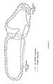
- each of the two power-dividing networks would provide a single half-Canada beam as illustrated by the dashed lines in Figure 2, one for West Canada and one for East Canada. This arrangement would be unsatisfactory in the area where the two beams touch or overlap in that insufficient flux would be available in that area.
- the variable power divider shown in Figure 1 if the first region beam is to be formed, the variable power divider can be switched into Position 1 and most of the transmitter power (approximately ninety percent) is switched to the first region or West Canada subarray and the balance of the power (approximately ten percent) is fed to the second region or East Canada subarray.
- variable power divider is switched to Position 2 and most (approximately ninety percent) of the transmitter power is switched to the second region or East Canada subarray, with the balance (approximately ten percent) being fed to the first region or West Canada subarray. In this manner, the overlap region is adequately covered as illustrated by the solid line shown in Figure 2.
- the variable power divider is set to Position 3 and roughly equal amounts of power are delivered to the two half-Canada feed horn arrays.
- FIG 3 there is shown a modification of the prior art RBFN shown in Figure 1 in that there is a special overlap region subarray consisting of at least two feed horns and an associated dual-mode power-dividing network.
- One type of dual-mode power-dividing network that is suitable is a 3 dB, ninety degree hybrid directional coupler, with two input ports and two output ports. The two output ports are connected to the two feed horns associated with the overlap region.
- One input port is connected to a first region or West Canada power-dividing network and the other input is connected to a second region or East Canada power-dividing network.
- variable power divider When the variable power divider is in Position 1, all power is transferred into the first region or West Canada beam-forming network, with a small portion flowing through the dual-mode power divider to provide coverage of the overlap region. By switching the variable power divider to Position 2, all power is transferred into the second region or East Canada beam-forming network, with a small portion flowing through the dual-mode power divider to provide coverage of the overlap region.
- These West Canada and East Canada beams are shown by the dashed lines in Figure 4.
- the variable power divider is placed in Position 3 and power is fed in approximately equal parts, with appropriate phasing, half to the West Canada network and half to the East Canada network.
- variable power divider When the variable power divider is in Position 1 or Position 2, this arrangement can cause poor coverage over the overlap region due to destructive interference of the two feeding paths into the overlap subarray.
- the quadrature phase coupler used in the overlap subarray causes the phase of the two feeding paths to be ninety degrees apart causing a power loss as there is no voltage addition between the two paths.
- FIG. 5 there is shown an RBFN in accordance with the present invention.
- the RBFN has a waveguide R-switch and associated output connecting waveguide runs that lead to a dual-mode power-dividing network.
- the dual-mode power-dividing network consists of an assembly of directional couplers and has two input ports and three output ports. By an appropriate choice of coupling values, one appropriate set of values being shown in Figure 5, it is possible to vary the amounts of power delivered to each of the three output ports from each of the two input ports.
- the three output ports are connected to three subarray power-dividing networks.
- a first region power-dividing network consists of an assemblage of directional couplers and compensating phase shifters. This network has one input port and N W output ports. Each of the N W output ports in connected to a feed horn of the first region feed horn array. By way of example, the first region could be the western half of Canada.
- a second region power-dividing network also consists of an assemblage of directional couplers and compensating phase shifters.
- This second region is geographically adjacent to said first region and has one input and N E output ports. Each of the N E output ports is connected to a feed horn of the second region feed horn array.
- the second region is geographically adjacent to the first region and, by way of example, can be the eastern half of Canada.
- An overlap region power-dividing network consists of an assemblage of directional couplers and compensating phase shifters and has one input port and N O output ports. Each of the N O output ports is connected to a feed horn in the overlap region feed horn array.
- the feed horn array consists of N W + N E + N O feed horns and can be any reasonable number of feed horns, depending on the area to be covered.
- the RBFN in accordance with the present invention can provide two overlapping half-beams when fed by appropriately phased inputs at Ports A and B shown in Figure 5. In addition, a whole coverage beam can be generated by appropriately phased inputs at Ports A and B.
- Table 3 The feeding and phasing requirements are summarized in Table 3:
- FIG 6 there is shown an enlarged version of the R-switch in three positions.
- the circuit contains, in addition to the R-switch, a Magic T, which is used as an H-Plane splitter.
- the R-switch has three waveguide paths, a central path and two outer paths, the two outer paths containing phasing elements.
- the central path is path 2 and the outer paths are paths 1, 3.
- input power is fed into the R-switch path 2 as indicated with the output from path 2 connecting to the input of the Magic T.
- the Magic T divides the power into two equal in-phase parts, one part being directed through R-switch path 1 to Port A and the other part being directed to Port B.
- R-switch path 1 contains phasing elements (eg. a change in waveguide dimensions) designed to realize the phase requirements shown in Table 3 for the West-Canada Beam.
- the R-switch is suitably connected to the two input ports of the dual-mode network, one output port from said dual-mode network being connected to an input port for said first region network.
- a second output from the dual-mode network is connected to an input for said second region network and a third output from said dual-mode network is connected to an input for said overlap network.
- the R-switch has three distinct waveguide paths and is operable in three distinct positions so that:
- the power being fed to the feed horns of any one of the regions has the same phase.
- FIG. 7A An alternative design for achieving similar reconfiguration as that shown in Figures 5 and 6 is shown in Figure 7A where a variable phase shifter is used in conjunction with a Magic T to vary the phase difference between the outputs of the Magic T before feeding equal amplitude signals to the two input ports of the dual-mode power-divider. In this way, it is possible to provide three equally-phased outputs. Only part of the RBFN is shown in Figure 7A. The three outputs from the dual-mode power-divider are connected to the three subarrays (not shown in Figure 7A) in the same manner as shown in Figure 5. The dual-mode power-divider is the same as that shown in Figure 5. The Magic T and variable phase shifter replace the R-switch and Magic T shown in Figure 5. This system can be made to operate in the same way as the RBFN of Figure 5.
- variable phase shifter shown in Figure 7A is operable in three distinct positions so that:
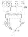
- FIG 7B there is shown a further variation in the RBFN of the present invention.
- the RBFN has an n-way in-phase power-divider and n variable phase shifters, one for each input port of an n-mode power-dividing network that replaces the dual-mode power-dividing network shown in Figure 5.
- Each output port is connected to a region power-dividing network, there being m regions.
- Each region contains a subarray of feed horns so that there are m regions of feed horns N1, N2, N3 ... N m .
- the n-way power-divider has at least m distinct positions so that at least m distinct beams with overlap can be formed.
- the power being fed to the feed horns of the m regions has the same phase.
- m 3
- the RBFNs shown in Figures 5 and 7A can be formed.
- phase of the power at the East Canada feed horns is one hundred and eighty degrees and the phase of the power at the West Canada and overlap feed horns (i.e. 9 to 17) is zero degrees.
- the phase of the power at all feed horns is zero degrees.
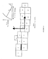
- the phase of the power at the East Canada feed horns i.e. 1 to 8
- the phase of the power at the overlap feed horns i.e. 9 to 11
- the phase of the power at the West Canada feed horns i.e. 12 to 17
- the phase of the power at each of the feed horns of any one region is the same.
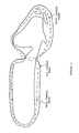
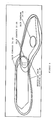
- the RBFN designed to produce the results shown in Table 4 with the feed horn arrangement shown in Figure 8 will produce the coverage shown in Figure 9 when the R-switch is in Positions 1 and 2.
- the coverage when the R-switch is in Position 3 is that shown in Figure 10.
- the examples used in the present application are East Canada, West Canada and All Canada positions, these are examples only and the RBFN in accordance with the present invention can be used in any region or regions to divide power from a transmitter. It is believed that the RBFN of the present invention has a cost advantage over prior art RBFNs, due to the large power saving when the R-switch is in Positions 1 and 2 of approximately one million dollars per channel.
Landscapes
- Variable-Direction Aerials And Aerial Arrays (AREA)
Applications Claiming Priority (2)
| Application Number | Priority Date | Filing Date | Title |
|---|---|---|---|
| CA519130 | 1986-09-26 | ||
| CA000519130A CA1226934A (fr) | 1986-09-26 | 1986-09-26 | Reseau generateur de faisceau reconfigurable alimentant ces diverses regions en phase |
Publications (2)
| Publication Number | Publication Date |
|---|---|
| EP0261983A2 true EP0261983A2 (fr) | 1988-03-30 |
| EP0261983A3 EP0261983A3 (fr) | 1989-09-20 |
Family
ID=4134022
Family Applications (1)
| Application Number | Title | Priority Date | Filing Date |
|---|---|---|---|
| EP87308512A Withdrawn EP0261983A3 (fr) | 1986-09-26 | 1987-09-25 | Réseau de formation de faisceau à configuration variable rayonnant une puissance en phase dans chaque région |
Country Status (3)
| Country | Link |
|---|---|
| US (1) | US4814775A (fr) |
| EP (1) | EP0261983A3 (fr) |
| CA (1) | CA1226934A (fr) |
Cited By (2)
| Publication number | Priority date | Publication date | Assignee | Title |
|---|---|---|---|---|
| EP0396015A1 (fr) * | 1989-05-02 | 1990-11-07 | Hughes Aircraft Company | Transpondeur à possibilité de sélection de faisceaux utilisant les mêmes éléments d'antenne et d'alimentation! |
| EP0504552A1 (fr) * | 1991-01-23 | 1992-09-23 | SELENIA SPAZIO S.p.A. | Réseau de formation de faisceaux pour une antenne multifaisceaux à modes multiples à réflecteur |
Families Citing this family (24)
| Publication number | Priority date | Publication date | Assignee | Title |
|---|---|---|---|---|
| US4949092A (en) * | 1984-11-08 | 1990-08-14 | Highes Aircraft Company | Modularized contoured beam direct radiating antenna |
| FR2672436B1 (fr) * | 1991-01-31 | 1993-09-10 | Europ Agence Spatiale | Dispositif de controle electronique du diagramme de rayonnement d'une antenne a un ou plusieurs faisceaux de direction et/ou de largeur variable. |
| US5576721A (en) * | 1993-03-31 | 1996-11-19 | Space Systems/Loral, Inc. | Composite multi-beam and shaped beam antenna system |
| US5422647A (en) * | 1993-05-07 | 1995-06-06 | Space Systems/Loral, Inc. | Mobile communication satellite payload |
| GB2288913B (en) | 1994-04-18 | 1999-02-24 | Int Maritime Satellite Organiz | Satellite payload apparatus with beamformer |
| IT1272984B (it) * | 1994-05-17 | 1997-07-01 | Space Eng Srl | Antenna a riflettore o a lente, a fasci sagomati o a scansione di fascio |
| US5539415A (en) * | 1994-09-15 | 1996-07-23 | Space Systems/Loral, Inc. | Antenna feed and beamforming network |
| IT1284301B1 (it) * | 1996-03-13 | 1998-05-18 | Space Engineering Spa | Antenna a singolo o a doppio riflettore, a fasci sagomati, a polarizzazione lineare. |
| GB2317056A (en) * | 1996-09-04 | 1998-03-11 | Marconi Gec Ltd | Signal processor system for a phased array antenna |
| US6072432A (en) * | 1997-05-02 | 2000-06-06 | Radio Frequency Systems, Inc. | Hybrid power tapered/space tapered multi-beam antenna |
| US6246364B1 (en) * | 1999-06-18 | 2001-06-12 | Hughes Electronics Corporation | Light-weight modular low-level reconfigurable beamformer for array antennas |
| DE69939017D1 (de) * | 1999-09-22 | 2008-08-14 | Lucent Technologies Inc | Optisches Netzwerk mit Leistungsteilern |
| US6295026B1 (en) * | 1999-11-19 | 2001-09-25 | Trw Inc. | Enhanced direct radiating array |
| US6650290B1 (en) * | 2000-08-02 | 2003-11-18 | Lucent Technologies Inc. | Broadband, low loss, modular feed for phased array antennas |
| US7233217B2 (en) * | 2001-08-23 | 2007-06-19 | Andrew Corporation | Microstrip phase shifter |
| US7221239B2 (en) * | 2002-11-08 | 2007-05-22 | Andrew Corporation | Variable power divider |
| BR0215914A (pt) * | 2002-11-08 | 2006-05-02 | Ems Technologies Inc | divisor de potência variável |
| US6868043B1 (en) * | 2003-02-20 | 2005-03-15 | Bbnt Solutions Llc | Beam broadening with maximum power in array transducers |
| US7557675B2 (en) * | 2005-03-22 | 2009-07-07 | Radiacion Y Microondas, S.A. | Broad band mechanical phase shifter |
| US20140313081A1 (en) * | 2013-04-17 | 2014-10-23 | Nokia Siemens Networks Oy | Multiple Beam Formation for RF Chip-Based Antenna Array |
| US11855680B2 (en) * | 2013-09-06 | 2023-12-26 | John Howard | Random, sequential, or simultaneous multi-beam circular antenna array and beam forming networks with up to 360° coverage |
| US10283862B2 (en) * | 2016-10-17 | 2019-05-07 | Huawei Technologies Co., Ltd. | Phase-mode feed network for antenna arrays |
| US10790586B2 (en) | 2017-06-15 | 2020-09-29 | Huawei Technologies Co., Ltd. | Adjustable stacked phase-mode feed for 2D steering of antenna arrays |
| CN113451786B (zh) * | 2021-06-25 | 2022-08-16 | 重庆两江卫星移动通信有限公司 | 一种紧凑型馈电网络与圆极化天线阵列的控制方法 |
Family Cites Families (7)
| Publication number | Priority date | Publication date | Assignee | Title |
|---|---|---|---|---|
| US4201963A (en) * | 1978-01-26 | 1980-05-06 | Communications Satellite Corporation | 3-Position, 4-port waveguide switch |
| US4257050A (en) * | 1978-02-16 | 1981-03-17 | George Ploussios | Large element antenna array with grouped overlapped apertures |
| US4228436A (en) * | 1978-04-03 | 1980-10-14 | Hughes Aircraft Company | Limited scan phased array system |
| FR2541518A1 (fr) * | 1982-10-26 | 1984-08-24 | Thomson Csf | Dispositif d'alimentation d'une antenne reseau a faisceau de balayage |
| US4503434A (en) * | 1983-05-02 | 1985-03-05 | Ford Aerospace & Communications Corporation | Lossless arbitrary output dual mode network |
| US4499471A (en) * | 1983-05-02 | 1985-02-12 | Ford Aerospace & Communications Corporation | Reconfigurable dual mode network |
| US4612548A (en) * | 1984-06-01 | 1986-09-16 | Raytheon Company | Multi-port radio frequency networks for an antenna array |
-
1986
- 1986-09-26 CA CA000519130A patent/CA1226934A/fr not_active Expired
-
1987
- 1987-03-12 US US07/025,271 patent/US4814775A/en not_active Expired - Fee Related
- 1987-09-25 EP EP87308512A patent/EP0261983A3/fr not_active Withdrawn
Cited By (2)
| Publication number | Priority date | Publication date | Assignee | Title |
|---|---|---|---|---|
| EP0396015A1 (fr) * | 1989-05-02 | 1990-11-07 | Hughes Aircraft Company | Transpondeur à possibilité de sélection de faisceaux utilisant les mêmes éléments d'antenne et d'alimentation! |
| EP0504552A1 (fr) * | 1991-01-23 | 1992-09-23 | SELENIA SPAZIO S.p.A. | Réseau de formation de faisceaux pour une antenne multifaisceaux à modes multiples à réflecteur |
Also Published As
| Publication number | Publication date |
|---|---|
| CA1226934A (fr) | 1987-09-15 |
| US4814775A (en) | 1989-03-21 |
| EP0261983A3 (fr) | 1989-09-20 |
Similar Documents
| Publication | Publication Date | Title |
|---|---|---|
| US4814775A (en) | Reconfigurable beam-forming network that provides in-phase power to each region | |
| US4799065A (en) | Reconfigurable beam antenna | |
| RU2346363C2 (ru) | Система фазированной антенной решетки с регулируемым электрическим наклоном | |
| AU2004310213B2 (en) | Phased array antenna system with controllable electrical tilt | |
| US3295134A (en) | Antenna system for radiating directional patterns | |
| US5151706A (en) | Apparatus for electronically controlling the radiation pattern of an antenna having one or more beams of variable width and/or direction | |
| US4965587A (en) | Antenna which is electronically reconfigurable in transmission | |
| EP1987567B1 (fr) | Formeur de faisceaux partage en groupes a commande de phase | |
| US5128687A (en) | Shared aperture antenna for independently steered, multiple simultaneous beams | |
| US4907004A (en) | Power versatile satellite transmitter | |
| US6169513B1 (en) | Thinned multiple beam phased array antenna | |
| CN1795581B (zh) | 具有可变电倾角的相控阵天线系统 | |
| US4758843A (en) | Printed, low sidelobe, monopulse array antenna | |
| US5038147A (en) | Electronically scanned antenna | |
| JPH01503666A (ja) | アクティブ・フェーズ・アレイ・アンテナ用の等パワー増幅器システムおよびその配置方法 | |
| CN116318278B (zh) | 一种多波束成形网络及六波束基站天线 | |
| US5289193A (en) | Reconfigurable transmission antenna | |
| JPH033430A (ja) | 分配されたアンテナフィード素子を使用する選択的アンテナビームを具備するトランスポンダ | |
| US5548295A (en) | Multishaped beam direct radiating array antenna | |
| US4223283A (en) | Two into three port phase shifting power divider | |
| EP0795928A2 (fr) | Antenne à seul ou double réflecteur, à faisceaux conformés et à polarisation linéaire | |
| US3839720A (en) | Corporate feed system for cylindrical antenna array | |
| US4176359A (en) | Monopulse antenna system with independently specifiable patterns | |
| US4471361A (en) | Phase reconfigurable beam antenna system | |
| CN206003971U (zh) | 波束成形网络及其输入结构、三波束天线 |
Legal Events
| Date | Code | Title | Description |
|---|---|---|---|
| PUAI | Public reference made under article 153(3) epc to a published international application that has entered the european phase |
Free format text: ORIGINAL CODE: 0009012 |
|
| AK | Designated contracting states |
Kind code of ref document: A2 Designated state(s): DE FR GB IT SE |
|
| PUAL | Search report despatched |
Free format text: ORIGINAL CODE: 0009013 |
|
| AK | Designated contracting states |
Kind code of ref document: A3 Designated state(s): DE FR GB IT SE |
|
| 17P | Request for examination filed |
Effective date: 19900306 |
|
| 17Q | First examination report despatched |
Effective date: 19920218 |
|
| STAA | Information on the status of an ep patent application or granted ep patent |
Free format text: STATUS: THE APPLICATION IS DEEMED TO BE WITHDRAWN |
|
| 18D | Application deemed to be withdrawn |
Effective date: 19930625 |
|
| RIN1 | Information on inventor provided before grant (corrected) |
Inventor name: DOWNS, HENRY Inventor name: RAAB, ANTHONY ROWLAND |