EP0262097A2 - Dispositif automatique de nettoyage, en particulier pour avion - Google Patents
Dispositif automatique de nettoyage, en particulier pour avion Download PDFInfo
- Publication number
- EP0262097A2 EP0262097A2 EP87830011A EP87830011A EP0262097A2 EP 0262097 A2 EP0262097 A2 EP 0262097A2 EP 87830011 A EP87830011 A EP 87830011A EP 87830011 A EP87830011 A EP 87830011A EP 0262097 A2 EP0262097 A2 EP 0262097A2
- Authority
- EP
- European Patent Office
- Prior art keywords
- fact
- system pursuant
- aircraft
- moving equipment
- equipment
- Prior art date
- Legal status (The legal status is an assumption and is not a legal conclusion. Google has not performed a legal analysis and makes no representation as to the accuracy of the status listed.)
- Withdrawn
Links
Images


Classifications
-
- B—PERFORMING OPERATIONS; TRANSPORTING
- B64—AIRCRAFT; AVIATION; COSMONAUTICS
- B64F—GROUND OR AIRCRAFT-CARRIER-DECK INSTALLATIONS SPECIALLY ADAPTED FOR USE IN CONNECTION WITH AIRCRAFT; DESIGNING, MANUFACTURING, ASSEMBLING, CLEANING, MAINTAINING OR REPAIRING AIRCRAFT, NOT OTHERWISE PROVIDED FOR; HANDLING, TRANSPORTING, TESTING OR INSPECTING AIRCRAFT COMPONENTS, NOT OTHERWISE PROVIDED FOR
- B64F5/00—Designing, manufacturing, assembling, cleaning, maintaining or repairing aircraft, not otherwise provided for; Handling, transporting, testing or inspecting aircraft components, not otherwise provided for
- B64F5/30—Cleaning aircraft
Definitions
- This invention refers to an automatic washing system particularly for aircraft and aircraft parts.
- the detergent liquids are sprayed using the same equipment that will later be employed to rinse the aircraft off with water, such equipment including hoses, nozzles, guns, lances and the like.
- these tools are normally handled and supported by specialized cleaners, who are often moved close to the parts to be washed by service bridges or platforms.
- washing conditions nowadays are particularly slow and costl and apt time-wise to condition the checking operations that must follow the cleaning operation and to delay aircraft availability.
- This invention aims at eliminating the above incon- venienees by suggesting an automatic washing system particularly for aircraft and aircraft parts and capable of performing the washing in an automatic manner as well as in safe and extremely fast conditions.
- an important aim of the invention is to create an automatic washing system, particularly for aircraft and aircraft parts, capable of avoiding the presence of personnel in environmentally hazardous areas.
- Not the least important purpose of the invention is to set up an aytomatic washing system, particu- laxly fox airaraft and aircraft parts, capable of speeding up the washing of the aircraft and relieve the washing people from the conditions of hardship conrlected with the task.
- an automatic washing system particularly for aircraft and aricraft parts, character zed by the fact that it includes at least one set of moyable equipment running on predetermined routes, such equipment to include kinematio organs for washing the parts of the aircraft subject to periodical cleaning, driving means for the said kinematic organs to be supplied with detergent fluids, at least one control station for the said kinematic equipment and filling sta- tione, the said preddetermined routes being apt to reach the said parts of an airoraft stationed in. a properly arranged area of the airport.
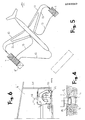
- the automatic washing system particularly for aircraft and aircrafteparts pursuant to the invention is coinprehensively indi- caded by reference number 1, and it includes at least one moving set of moving equipment, indicated by .. noumber 2, which includes a number of kinematio organs a comprehensively indicated by 3 apt to wash the various parts of the aircraft eubject to periodical cleaning.
- Moving equipment 2 is also apt to support sezvoes and ecntrols of kinematic organs 3 and supply these with deteergents designed to be distributed over the parts of the aircraft to be washed, which detergents are supplied to the moving equipment when it is sheltered in the filling stations 4, which shall be more thoroughly detailed further ahead.
- a control station 5 is also envisaged, managed by a police officer stationed in a position enabling him to oversee, using also a closed television circuit associated with the moving. equipment of. a commercial type not showing in the figures, the progress and results of the washing operations.
- the number of the moving equipment may be worked out depending on the need to simultaneously clean more than one part of the aircraft, each equipment set being equipped with a frame 7 supported by two driving wheels 8 associated with a speed-reducing motor capable of providing the moving equipment with three working speeds, two of which operative and one driving the equipment up close to the aircraft, so as to vary the washing and moving times of the equipment and make it more flexible and suitable to the purpose it was designed for.
- the front part of frame 7 is also supported by a swivelign castor 10, near which is at least one front guiding wheel, and more exactly two front guiding wheels generically indicated 11, whereas close to the driving wheels is a rear guiding wheel 12 which, together with the front guiding wheels, enables the moving equipment to reach, along the predetermined routes 13, the parts to be washed of the aircraft paxked in the appropriate area of the runway, which parts need washing before being submitted to maintenance.
- a swivelign castor 10 near which is at least one front guiding wheel, and more exactly two front guiding wheels generically indicated 11, whereas close to the driving wheels is a rear guiding wheel 12 which, together with the front guiding wheels, enables the moving equipment to reach, along the predetermined routes 13, the parts to be washed of the aircraft paxked in the appropriate area of the runway, which parts need washing before being submitted to maintenance.
- the front and rear guiding wheels also show a rotating rudder associated via the pivot 15 with the moving equipment; .and on the side opposite to pivot 15 are bearings 16 and 17 located parallel to the rudder axis which engage in a sliding fashion in the pre-determined rails 13, which in their illustrated executive form are represented by channels 18 whose sides are reinforced with rails 19 solidly connected to them.
- the diameter of bearings 16 and 17 of the front and rear guiding ;wheels respectively is smaller than the distance between the two facing rails 19.
- the controls supported by the moving equipment include a water tank 20, side by side to detergent tank 22, so that both tanks can be filled up at the same'time from the automatie-opening filling outlets 21.
- Each of the water tanks 20 and detergent tanks 22 are provided with electric pumps 23 and 24 designed to suck the water and detergent and send them under pressure to the kinematic organs in charge of pro- jectang them against the aircraft parts to be cleaned.
- the moving equipment is also equipped with a data processing systems, gerrerically indicated 25, which activates a control unit 26, the task of the latter being to plan the operations of the moving equipment.
- the moving equipment is also provided with a motor-driven coil 27 in charge of laying link cable 28 via a laying guide 29, the cable 28. being laid on the battom of ohannels 19 and through which all commands and funotions are transmitted to the moving equipment by the control station.
- the motor-driven cable winder is also associated at one end withe frame 7 via hinge 30 which permits it to oscillate parallel to the ground of the moyin equipment, whereae at the opposite end it engages in a sliding fashion in rail 19 through at least one of the said guiding wheels.
- the front guiding wheel of the moving equipment is provided with a scratching palette 51, whose task it is to remove any foreign matter from chanhel(s) 19 constituting the prearranged routes of the moving equipment.
- each set of moving equipment is sheltered in filling stations, one wall of which houses a plurality of dispensers 32 for each moving equipment, the said dispensers designed respectively to replenish the water and detergent tanks.
- Dispenserw 32 can also. advantageousl move along an orthogonal plane to wall 31 and to the station floor, and their free ends have a. curved design better to fit into supply mouthpieces 21 of the moving equipment, which also open automatioally.
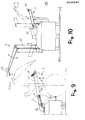
- each moving equipment set is prwided with kinematio organs to wash the various parts of the aircraft, and they include swiveling arm 40 consisting of two reciprocally articulating sections, the arm hinging round an axle perpendicular to the frame of the moving equipment.
- Arm 40 is driven. by at least control cylinder, or more precisely by cylirtder 41, and on the free end of the arm is an initial set of detergent nozzles 42 associated with the arm in a rotary fashion so as to move along a parllel plane to the side face of the arm itself.
- the moving equipment also incorporates a second set of spraying nozzles 43 associated with it in a swiveling fashion so as to be operated synchronically with spraying nqzzles 42 when washing aircraft carroages generically marked 44.
- the section designed to face the aircraft to be washed is sensor 45, designed to position the moving equipment relatively to the airoraft oarriage(s).
- the kinematic organs include washing means generically marked 50 devoted to clea- ning the housings of both main carriages 48 and of the fore-carriage of the aircraft.
- the washing means devoted to cleaning the housings of the main carriages are provided with translation guide 51 and with slide 52 equipped with pantograph 53 and the, guide projects from the moving equipment in a direction substantially parallel to the moving equipment and parallel to its translation ground.
- pantograph On its free end opposite the end attached to the slide 52, pantograph holds a third set of dispensing nozzles 54, which advantagegusly, rotate round a spraying axis substantially to the ground so they fully spray the detergent liquid inside the carriage hood and cleanse it thoroughly.
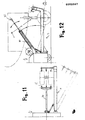
- the kinematio organs include at least one or more precisely two arms 60 and 61, which vertically extend telescope-like upward from the moving equipment substantially perpendicularly to the ground on which it runs.
- Each telescppic arm 60 and 61 ends with fluid dispensers 62 designed to wash the slats and flaps of the aircraft wings.
- telescopic arm 60 devoted to washing the flaps comprises at least one swiveling first section and at least one translating second section in respect of the first section provided with the fluid dispensers 62.
- the washing means and more precisely those devoted to washing the fore carriages of aircraft, include a swiviling arm 70 moving along a plane parallel to the axis of the moving equipment and to the ground on which the moving e quipment runs.
- the smaller arm 70 is advantageously extensible telescope-like so it can reach the interstices of the fore carriage hood, and it holds spraying nozzles 71 to wash the said fore carriage hood.
- the automatic washing system pursuant to this invention operates as follows: After the aircraft to be washed has been positioned in the area of the runway devoted to that purpose, moving equipment 2 is directed to leave filling stations 4 and reach the parts of the aircraft to be washed along the prearranged routes 13. As the moving equipment reaches the desired position the kinematic organs are activated along with the spraying nozzles in charge of washin the different arts of the aircraft. When the washing is over the moving equipment is moved beck and sheltered again inside filling stations 4 and filled up with frosh water and detergent fluid.
- the washing system pursuant to the invention fully meets the requirements, as it makes it possible automatically to wash airoraft quickly and without operators being present in hazardous areas of the runway.
- the invention is susceptible to numerous modifications and changes, all of which covered by the basic concept of the invention furthermore, all the details may be replaced with technically equivalent elements; so, for instance, the prearranged routes might consist, besides mechanical tracks, also of pneumatic, optical and electro magnetic tracks affording fields of force of known type and at any rate capable ot securing control on the operative distances and averting undesired contacts to occur among the moving equipment as it is moved.
Landscapes
- Engineering & Computer Science (AREA)
- Manufacturing & Machinery (AREA)
- Transportation (AREA)
- Aviation & Aerospace Engineering (AREA)
- Cleaning By Liquid Or Steam (AREA)
- Vehicle Cleaning, Maintenance, Repair, Refitting, And Outriggers (AREA)
Applications Claiming Priority (2)
| Application Number | Priority Date | Filing Date | Title |
|---|---|---|---|
| IT2160986 | 1986-09-05 | ||
| IT21609/86A IT1197173B (it) | 1986-09-05 | 1986-09-05 | Impianto di lavaggio automatico particolarmente per velivoli e loro parti |
Publications (2)
| Publication Number | Publication Date |
|---|---|
| EP0262097A2 true EP0262097A2 (fr) | 1988-03-30 |
| EP0262097A3 EP0262097A3 (fr) | 1989-07-26 |
Family
ID=11184280
Family Applications (1)
| Application Number | Title | Priority Date | Filing Date |
|---|---|---|---|
| EP87830011A Withdrawn EP0262097A3 (fr) | 1986-09-05 | 1987-01-16 | Dispositif automatique de nettoyage, en particulier pour avion |
Country Status (2)
| Country | Link |
|---|---|
| EP (1) | EP0262097A3 (fr) |
| IT (1) | IT1197173B (fr) |
Cited By (7)
| Publication number | Priority date | Publication date | Assignee | Title |
|---|---|---|---|---|
| US5720069A (en) * | 1993-08-31 | 1998-02-24 | Putzmeister-Werk Maschinenfabrik Gmbh | Arrangement for surface treatment, especially the cleaning of the surfaces of large objects |
| US5769954A (en) * | 1993-08-13 | 1998-06-23 | Putzmeister Aktiengesellschaft | Process and device for treating the surface of large objects |
| US5833762A (en) * | 1993-08-13 | 1998-11-10 | Fraunhofer-Gesellschaft Zur Foerderung Der Angewandten Forschung E.V. | Process for treating an object, in particular an airplane |
| WO2005120953A1 (fr) * | 2004-06-14 | 2005-12-22 | Gas Turbine Efficiency Ab | Systeme servant a laver un moteur de turbine a gaz aerienne |
| US8206478B2 (en) | 2010-04-12 | 2012-06-26 | Pratt & Whitney Line Maintenance Services, Inc. | Portable and modular separator/collector device |
| US9932895B2 (en) | 2013-10-10 | 2018-04-03 | Ecoservices, Llc | Radial passage engine wash manifold |
| CN114850122A (zh) * | 2022-03-21 | 2022-08-05 | 任相广 | 一种用于飞机的非接触柔性清洗系统 |
Families Citing this family (1)
| Publication number | Priority date | Publication date | Assignee | Title |
|---|---|---|---|---|
| CN106423605B (zh) * | 2016-12-07 | 2018-09-21 | 中国民航大学 | 通用型航空发动机在翼清洗喷射设备 |
Family Cites Families (5)
| Publication number | Priority date | Publication date | Assignee | Title |
|---|---|---|---|---|
| DE1187943B (de) * | 1962-08-08 | 1965-02-25 | Johann Sulzberger | Selbsttaetige Waschanlage fuer Kraftfahrzeuge |
| US3460177A (en) * | 1967-08-28 | 1969-08-12 | Brown Eng Co Inc | Aircraft washing system |
| US3775799A (en) * | 1972-07-03 | 1973-12-04 | W Talbot | Car-wash installations |
| GB1384758A (en) * | 1972-07-31 | 1975-02-19 | Thornton Trump W E | Aircraft washing and dusting apparatus |
| CH603383A5 (fr) * | 1976-01-29 | 1978-08-15 | Laszlo Arato |
-
1986
- 1986-09-05 IT IT21609/86A patent/IT1197173B/it active
-
1987
- 1987-01-16 EP EP87830011A patent/EP0262097A3/fr not_active Withdrawn
Cited By (16)
| Publication number | Priority date | Publication date | Assignee | Title |
|---|---|---|---|---|
| US5769954A (en) * | 1993-08-13 | 1998-06-23 | Putzmeister Aktiengesellschaft | Process and device for treating the surface of large objects |
| US5833762A (en) * | 1993-08-13 | 1998-11-10 | Fraunhofer-Gesellschaft Zur Foerderung Der Angewandten Forschung E.V. | Process for treating an object, in particular an airplane |
| US5720069A (en) * | 1993-08-31 | 1998-02-24 | Putzmeister-Werk Maschinenfabrik Gmbh | Arrangement for surface treatment, especially the cleaning of the surfaces of large objects |
| RU2554188C2 (ru) * | 2004-06-14 | 2015-06-27 | ЭКОСЕРВИСИЗ, ЭлЭлСи | Система для промывки авиационного газотурбинного двигателя |
| EP1897806A3 (fr) * | 2004-06-14 | 2008-09-03 | Gas Turbine Efficiency AB | Système de lavage d'un moteur de turbine à gaz aérienne |
| US8479754B2 (en) | 2004-06-14 | 2013-07-09 | Ecoservices, Llc | System for washing an aero gas turbine engine |
| US8628627B2 (en) | 2004-06-14 | 2014-01-14 | Ecoservices, Llc | Turboengine water wash system |
| WO2005120953A1 (fr) * | 2004-06-14 | 2005-12-22 | Gas Turbine Efficiency Ab | Systeme servant a laver un moteur de turbine a gaz aerienne |
| US9316115B2 (en) | 2004-06-14 | 2016-04-19 | Ecoservices, Llc | Turboengine wash system |
| US9376932B2 (en) | 2004-06-14 | 2016-06-28 | Ecoservices, Llc | Turboengine water wash system |
| US9657589B2 (en) | 2004-06-14 | 2017-05-23 | Ecoservices, Llc | System for washing an aero gas turbine engine |
| US9708928B2 (en) | 2004-06-14 | 2017-07-18 | Ecoservices, Llc | Turboengine water wash system |
| US10041372B2 (en) | 2004-06-14 | 2018-08-07 | Ecoservices, Llc | System for washing an aero gas turbine engine |
| US8206478B2 (en) | 2010-04-12 | 2012-06-26 | Pratt & Whitney Line Maintenance Services, Inc. | Portable and modular separator/collector device |
| US9932895B2 (en) | 2013-10-10 | 2018-04-03 | Ecoservices, Llc | Radial passage engine wash manifold |
| CN114850122A (zh) * | 2022-03-21 | 2022-08-05 | 任相广 | 一种用于飞机的非接触柔性清洗系统 |
Also Published As
| Publication number | Publication date |
|---|---|
| IT8621609A0 (it) | 1986-09-05 |
| EP0262097A3 (fr) | 1989-07-26 |
| IT1197173B (it) | 1988-11-30 |
| IT8621609A1 (it) | 1988-03-05 |
Similar Documents
| Publication | Publication Date | Title |
|---|---|---|
| US3277511A (en) | Adjustable width floor treating machine | |
| EP1263537B1 (fr) | Nettoyage de surfaces | |
| US3259138A (en) | Washing apparatus for motor vehicles | |
| US4941491A (en) | Method and apparatus for cleaning containers | |
| US4711257A (en) | Vehicle washing apparatus | |
| EP0262097A2 (fr) | Dispositif automatique de nettoyage, en particulier pour avion | |
| EP3228395B1 (fr) | Outil pour canaliser le liquide projeté et/ou pulvérisé par des équipements d'application de produits phytosanitaires | |
| US3178745A (en) | Machine for washing plastic shields for fluorescent lights | |
| US2756759A (en) | Apparatus for cleaning vehicles | |
| US3600224A (en) | Method and apparatus for cleaning large surfaces | |
| CN109018243A (zh) | 擦窗机及船舶 | |
| US3935610A (en) | Cleaning apparatus for overhead rails | |
| US4809720A (en) | Brushless vehicle washing apparatus | |
| US3729763A (en) | Wheel washing apparatus | |
| US4240175A (en) | Apparatus for washing the interior of a freight container | |
| DE3708087A1 (de) | Fahrbarer bodenreinigungsautomat | |
| US3037224A (en) | Device for washing truck bodies | |
| US4369541A (en) | Retractable wax, buff and polish apparatus for cars | |
| US3599650A (en) | Car wash | |
| US3581335A (en) | Apparatus for washing railway vehicles | |
| US6206013B1 (en) | Device for cleaning lamellar blinds and method for using the same | |
| US3324868A (en) | Car wash installation | |
| EP2465779B1 (fr) | Système et procédé automatisé pour le nettoyage de la surface intérieure d'un fuselage d'avion | |
| JPS6346954A (ja) | 静止車内部掃除装置 | |
| JP2866954B2 (ja) | 槽の自動洗浄装置 |
Legal Events
| Date | Code | Title | Description |
|---|---|---|---|
| PUAI | Public reference made under article 153(3) epc to a published international application that has entered the european phase |
Free format text: ORIGINAL CODE: 0009012 |
|
| AK | Designated contracting states |
Kind code of ref document: A2 Designated state(s): AT BE CH DE ES FR GB GR LI LU NL SE |
|
| PUAL | Search report despatched |
Free format text: ORIGINAL CODE: 0009013 |
|
| AK | Designated contracting states |
Kind code of ref document: A3 Designated state(s): AT BE CH DE ES FR GB GR LI LU NL SE |
|
| 17P | Request for examination filed |
Effective date: 19891009 |
|
| 17Q | First examination report despatched |
Effective date: 19900905 |
|
| STAA | Information on the status of an ep patent application or granted ep patent |
Free format text: STATUS: THE APPLICATION IS DEEMED TO BE WITHDRAWN |
|
| 18D | Application deemed to be withdrawn |
Effective date: 19911030 |
|
| RIN1 | Information on inventor provided before grant (corrected) |
Inventor name: VOUTCHINITCH, PAVLE |